1
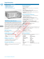
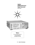
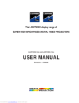
Test Equipment Solutions Datasheet
Test Equipment Solutions Ltd specialise in the second user sale, rental and distribution of
quality test & measurement (T&M) equipment. We stock all major equipment types such as
spectrum analyzers, signal generators, oscilloscopes, power meters, logic analysers etc from
all the major suppliers such as Agilent, Tektronix, Anritsu and Rohde & Schwarz.
We are focused at the professional end of the marketplace, primarily working with customers
for whom high performance, quality and service are key, whilst realising the cost savings that
second user equipment offers. As such, we fully test & refurbish equipment in our in-house,
traceable Lab. Items are supplied with manuals, accessories and typically a full no-quibble 2
year warranty. Our staff have extensive backgrounds in T&M, totalling over 150 years of
combined experience, which enables us to deliver industry-leading service and support. We
endeavour to be customer focused in every way right down to the detail, such as offering free
delivery on sales, covering the cost of warranty returns BOTH ways (plus supplying a loan
unit, if available) and supplying a free business tool with every order.
As well as the headline benefit of cost saving, second user offers shorter lead times, higher
reliability and multivendor solutions. Rental, of course, is ideal for shorter term needs and
offers fast delivery, flexibility, try-before-you-buy, zero capital expenditure, lower risk and off
balance sheet accounting. Both second user and rental improve the key business measure of
Return On Capital Employed.
We are based near Heathrow Airport in the UK from where we supply test equipment
worldwide. Our facility incorporates Sales, Support, Admin, Logistics and our own in-house
Lab.
All products supplied by Test Equipment Solutions include:
- No-quibble parts & labour warranty (we provide transport for UK mainland addresses).
- Free loan equipment during warranty repair, if available.
- Full electrical, mechanical and safety refurbishment in our in-house Lab.
- Certificate of Conformance (calibration available on request).
- Manuals and accessories required for normal operation.
- Free insured delivery to your UK mainland address (sales).
- Support from our team of seasoned Test & Measurement engineers.
- ISO9001 quality assurance.
Test equipment Solutions Ltd
Unit 8 Elder Way
Waterside Drive
Langley
Berkshire
SL3 6EP
T: +44 (0)1753 596000
F: +44 (0)1753 596001
Email: [email protected]
Web: www.TestEquipmentHQ.com
Signal Generators
298
E4438C
Vector Signal Generators (cont.)
•
•
•
•
6 GHz frequency range
160 MHz RF modulation bandwidth
320 Mbytes baseband memory
6 Gbyte non-volatile waveform storage
Powerful Standard Features
• Excellent spectral purity
• Electronic attenuator
• Simple softkey menu structure allows access to sophisticated
features
• Built-in help
• Differential and single-ended I/Q outputs
• Suite of I/Q adjustments: gain, DC offsets, quadrature skew
• Save and recall instrument settings
• IntuiLink software allows easy data exchange from Microsoft®
applications
• 10BaseT LAN and GPIB interfaces
Superior Dual Mode Baseband Generator
E4438C RF Vector Signal Generator
4
The Agilent E4438C ESG vector signal generator meets the needs of
engineers who are designing and developing the next generation of
wireless communication systems and is well suited for production
test environments. An assortment of standards-based receiver and
component test software for 3G and emerging communications
formats are available to simplify the signal configuration process.
The E4438C ESG vector signal generator’s performance, extended
frequency range, increased memory for waveform playback and
storage, and application-specific personalities make it the clear
choice for development and manufacturing from the component to
the system level.
6 GHz Frequency Range
E4438C ESG provides different frequency options to suit your need:
1, 2, 3, 4 or 6 GHz
• Dual mode capability supports both waveform playback and
real-time signal generation
• 80 MHz RF modulation bandwidth
• 64 Msamples (320 Mbytes) of waveform playback memory
• Generate waveforms at up to 100 Msamples/s
• Hardware resampling technology eliminates need for multiple
reconstruction filters
• 16-bit DAC for improved dynamic range
• Flexible baseband reference clock 250 kHz to 100 MHz
• Industry standard filters or user-definable FIR filters
• Set Eb/No or C/N ratio for W-CDMA, cdma2000, WiMAX, Digital
Video, and more
• Generate AWGN with up to 80 MHz bandwidth
• Generate phase coherent carriers
• Polar modulation
Baseband Studio
Baseband Studio is a suite of baseband signal applications and
accessories that work with the E4438C ESG vector signal generator
to emulate real-world signal conditions.
• Fading
• Digital inputs and outputs
• Waveform capture and playback
• CPRI RE test
For more information, go to page 341
160 MHz RF Modulation Bandwidth
Signal Creation Software
• Ideal for multi-carrier signals
• Up to 160 MHz RF modulation bandwidth using external I/Q
inputs
• 80 MHz RF modulation bandwidth using internal baseband
generator
The software is used for the development and generation of
waveforms with the internal baseband generator.
• TD-SCDMA
• AWGN
• W-CDMA
• Noise power ratio
• EDGE/GSM
• Enhanced multitone
• 1xEV-DO/1xEV-DV
• Custom
• cdma2000/cdmaOne
• Pulse
• NADC/PDC
• M/AM/FM
• PHS
• S-DMB
• DECT
• HSDPA
• TETRA
• Pulse building
• GPS
• Jitter injection
• 802.11a/b/g/j/p/n WLAN • 802.16 (WiMAX)
• Bluetooth™
• Digital Video
• T-DMB
• DVB-T/H/C/S, ISDB-T, ATSC, DTMB
• Toolkit
320 Mbytes Baseband Memory
• 64 Msamples (320 Mbytes) for waveform playback
• 64x the memory of the previous generation
• Build longer, more complex waveforms
6 Gbytes Non-Volatile Memory
• 1.2 Gsamples (6 Gbytes) for storing waveforms and instrument
states
• Eliminate waveform build times in manufacturing and
development
English URL www.agilent.com/find/products
For more information, go to page 310
Signal Generators
Vector Signal Generators (cont.)
Specifications For Frequency and Power Characteristics
Level Accuracy [dB]
Frequency
Frequency Range
Option:
• 501: 250 kHz to 1 GHz
• 502: 250 kHz to 2 GHz
• 503: 250 kHz to 3 GHz
• 504: 250 kHz to 4 GHz
• 506: 250 kHz to 6 GHz (requires Option UNJ)
Frequency Minimum
100 kHz1
Frequency Resolution
0.01 Hz
Frequency Switching Speed4
Option 501-504
(<35 ms) (<52 ms)
(<9 ms) (<9 ms)
[For hops <5 MHz within a band]
Digital modulation
on
(<9 ms) (<9 ms)
(<9 ms) (<9 ms)
off
(<9 ms) (<9 ms)
(<9 ms) (<9 ms)
250 kHz to 2 GHz
2 to 3 GHz
3 to 4 Ghz
(<41 ms) (<57 ms)
(<16 ms) (<17 ms)
(<33 ms) (<53 ms)
(<12 ms) (<14 ms)
<±1 ppm/yr <±0.1 ppm/yr or
<±0.0005 ppm/day after 45 days
(<±1 ppm) (<±0.05 ppm)
(<±0.1 ppm) (<±0.002 ppm)
(+5% to –10%) (+5% to –10%)
±0.5
±0.6
±0.6
±0.5
±0.6
±0.7
±0.7
±0.8
±0.8
(±1.5)
(±2.5)
(±2.5)
+10 to
–50 dBm
–50 to
–120 dBm
–120 to
–127 dBm
<–127 dBm
250 kHz to 2 GHz
2 to 3 GHz
3 to 4 GHz
±0.5
±0.6
±0.8
±0.7
±0.8
±0.9
±0.8
±1.0
±1.3
(±1.5)
(±2.5)
(±2.5)
+7 to
–50 dBm
–50 to
–110 dBm
–110 to
–127 dBm
<–127 dBm
±0.6
±0.6
±0.8
±0.8
±0.8
±0.8
±0.9
±0.9
±0.8
±1.0
±1.5
(±1.5)
(±1.5)
(±2.5)
(±2.5)
With Option 5064, 6
250 kHz to 2 GHz
2 to 3 GHz
3 to 4 GHz
4 to 6 GHz
Option
501-504
1, 2, 5, 10 MHz ± 0.2 ppm
–3.5 dBm to 20 dBm
50 Normal operation [ALC on]
(<15 ms)
When using power search manual (<83 ms)
When using power search auto
(<103 ms)
Output Power
Power
Option
UNB
Option
506
(<21 ms)
(<95 ms)
(<119 ms)
(<21 ms)
(<95 ms)
(<119 ms)
Spectral Purity
SSB Phase Noise (at 20 kHz offset)4
Option 501-504
With Option UNB Option 506
+11 to –136 dBm
+13 to –136 dBm
+10 to –136 dBm
+7 to –136 dBm
—
+15 to –136 dBm
+17 to –136 dBm
+16 to –136 dBm
+13 to –136 dBm
—
+12 to –136 dBm
+14 to –136 dBm
+13 to –136 dBm
+10 to –136 dBm
+10 to –136 dBm
Level Resolution
0.02 dB
Level Range with Attenuator Hold Active
250 kHz to 1 GHz
>1 to 3 GHz
>3 to 4 GHz
>4 to 6 GHz
<–127 dBm
Level Accuracy with Digital Modulation Turned On (relative to CW)
Conditions:
(with PRBS modulated data; if using I/Q inputs, √ I2 + Q2 = 0.5 Vrms,
nominal)4
Level Accuracy with ALC on
/4 DQPSK or QPSK formats
Conditions: With raised cosine or root-raised cosine filter and ≥0.35;
with 10 kHz ≤symbol rate ≤1 MHz; at RF freq ≥25 MHz; power ≤max
specified –3 dB
Option 501-504
With Option 506
±0.15 dB
±0.25 dB
Constant amplitude formats (FSK, GMSK, etc)
Option 501-504
With Option 506
±0.1 dB
±0.15 dB
Level Accuracy with ALC off 4, 7
(±0.15 dB) (relative to ALC on)
Conditions: After power search is executed, with burst off.
4
Level Switching Speed
RF Reference Output
• Frequency: 10 MHz
• Amplitude: 4 dBm ±2 dB
RF Reference Input Requirements
250 kHz to 250 MHz
>250 MHz to 1 GHz
>1 to 3 GHz
>3 to 4 GHz
>4 to 6 GHz
–120 to
–127 dBm
Power Level
Internal Reference Oscillator (Option 1E5)
Stability4
Frequency
Amplitude
Input impedance
–50 to
–120 dBm
Power Level
Sweep Modes
Operating Modes
Frequency step, amplitude step and arbitrary list
Dwell Time
1 ms to 60 s
Number of Points
2 to 65, 535
Temp (0 to 55° C)
Line voltage
Line voltage range
+7 to
–50 dBm
With Option UNB4, 5
Phase Offset
Phase is adjustable remotely (LAN, GPIB, RS-232) or via front panel in
nominal 0.1° increments
Aging rate
E4438C
Power Level
Option 501-504
Option 501-504 w/UNJ
With Option 506
Freq.2
Freq./Amp.3 Freq.2
Freq./Amp.3 Freq.2
Freq./Amp.3
Digital modulation
on
(<35 ms) (<49 ms)
off
(<9 ms) (<9 ms)
Option 501-504
With Option UNB Option 506
23 dB
20 dB
17 dB
—
27 dB
26 dB
23 dB
—
24 dB
23 dB
20 dB
20 dB
at 500 MHz
at 1 GHz
at 2 GHz
at 3 GHz
at 4 GHz
at 6 GHz
Option 501-504
With Option UNJ
(<–124 dBc/Hz)
(<–118 dBc/Hz)
(<–112 dBc/Hz)
(<–106 dBc/Hz)
(<–106 dBc/Hz)
N/A
<–135 dBc/Hz, (<–138 dBc/Hz)
<–130 dBc/Hz, (<–134 dBc/Hz)
<–124 dBc/Hz, (<–128 dBc/Hz)
<–121 dBc/Hz, (<–125 dBc/Hz)
<–118 dBc/Hz, (<–122 dBc/Hz)
<–113 dBc/Hz, (<–117 dBc/Hz)
Residual FM4 (CW mode, 0.3 to 3 kHz BW, CCITT, rms)
• Option UNJ <N x 1 Hz (<N x 0.5 Hz)8
• Standard
– Phase noise mode 1 <N x 2 Hz
– Phase noise mode 2 <N x 4 Hz
1
2
3
4
5
6
7
8
English URL www.agilent.com/find/products
299
Performance below 250 kHz not guaranteed.
To within 0.1 ppm of final frequency above 250 MHz or within 100 Hz below 250 MHz.
Frequency switching time with the amplitude settled within ±0.1 dB.
Parentheses denote typical performance.
Quoted specifications for 23°C ± 5°C. Accuracy degrades by less than 0.01 dB/°C over full
temperature range. Accuracy degrades by 0.2 dB above +10 dBm, and by 0.8 dB above +13 dBm.
Quoted specifications for 23°C ± 5°C. Accuracy degrades by less than 0.02 dB/°C over
full temperature range. Accuracy degrades by 0.2 dB above +7 dBm.
When applying external I/Q signals with ALC off, output level will vary directly with I/Q
input level.
Refer to frequency bands on next page for N values.
4
Signal Generators
300
Vector Signal Generators (cont.)
E4438C
Specifications For Analog Modulation
Frequency Bands
Band
Frequency Range
N#
1
2
3
4
5
6
250 kHz to ≤250 MHz
>250 MHz to ≤500 MHz
>500 MHz to ≤1 GHz
>1 to ≤2 GHz
>2 to ≤4 GHz
>4 to ≤6 GHz
1
0.5
1
2
4
8
Frequency Modulation1, 3
Maximum Deviation
Option 501-504
With Option UNJ
N x 8 MHz
N x 1 MHz
Resolution
0.1% of deviation or 1 Hz, whichever is greater
Modulation Frequency Rate4 (deviation = 100 kHz)
Coupling
1 dB Bandwidth
3 dB Bandwidth
FM path 1 (DC)
FM path 2 (DC)
FM path 1 (AC)
FM path 2 (AC)
DC to 100 kHz
DC to 100 kHz
20 Hz to 100 kHz
20 Hz to 100 kHz
(DC to 10 MHz)
(DC to 0.9 MHz)
(5 Hz to 10 MHz)
(5 Hz to 0.9 MHz)
Deviation Accuracy2 (1 kHz rate, deviation <N x 100 kHz)
<±3.5% of FM deviation + 20 Hz
Phase Modulation1, 3
Resolution
0.1% of set deviation
Modulation Frequency Response4, 5
4
Standard
Mode
Maximum
Deviation
Allowable Rates (3 dB BW)
M Path 1
M Path 2
Normal BW
High BW8
N x 80 rad
N x 8 rad
N x 1.6 rad
DC to 100 kHz
(DC to 1 MHz)
(DC to 10 MHz)
Mode
Maximum
Deviation
Allowable Rates (3 dB BW)
M Path 1
M Path 2
Normal BW
High BW
N x 10 radians
N x 1 radians
DC to 100 kHz
(DC to 1 MHz)
DC to 100 kHz
(DC to 0.9 MHz)
(DC to 0.9 MHz)
With Option UNJ
DC to 100 kHz
(DC to 0.9 MHz)
Deviation Accuracy (1 kHz rate, Normal BW mode)
<±5% of deviation + 0.01 radians
Distortion5 (1 kHz rate, deviation <80 radians on Options 501-504,
<10 N radians on Option UNJ models, Normal BW mode) <1%
Amplitude Modulation1, 5 (fc >500 kHz)
Range
0 to 100%
Resolution
0.1%
Rates (3 dB bandwidth)
• DC coupled: 0 to 10 kHz
• AC coupled: 10 Hz to 10 kHz
Accuracy4, 7 1 kHz rate <±(6% of setting + 1%)
Distortion4, 7 (1 kHz rate, THD)
Option 501-504/Option UNJ
Option 506
30% AM
<1.5%
<1.5%
90% AM
(<4%)
(<5%)
Pulse Repetition Frequency4
ALC on (10 Hz to 250 kHz)
ALC off (DC to 1.0 MHz)
Level Accuracy4, 9 (relative to CW at ≤4 dBm Option 501-504, ≤7.5 dBm
Option UNB, ≤4.5 dBm Option 506)
(<±1 dB)
Internal Pulse Generator
• Square wave rate: 0.1 Hz to 20 kHz
• Pulse
Period: 8 µs to 30 seconds
Width: 4 µs to 30 seconds
Resolution: 2 µs
Internal Analog Modulation Source
(Provides FM, AM, pulse, and phase modulation signals and LF audio out)
Waveforms
sine, square, ramp, triangle, pulse, noise
Rate Range
Sine
0.1 Hz to 100 kHz
Square, ramp, triangle
0.1 Hz to 20 kHz
Resolution
0.1 Hz
Frequency Accuracy
same as RF reference source
Swept Sine Mode (frequency, phase continuous)
Operating modes
Triggered or continuous sweeps
Frequency range
0.1 Hz to 100 kHz
Sweep time
1 ms to 65 sec
Resolution
1 ms
Dual Sinewave Mode
Frequency range
0.1 Hz to 100 kHz
Amplitude ratio
0 to 100%
Amplitude ratio Resolution 0.1%
External Modulation Inputs
Modulation Types
Ext 1
FM, M, AM, pulse, and burst envelope
Ext 2
FM, M, AM, and pulse
LO/HI Indicator (100 Hz to 10 MHz BW, AC coupled inputs only). Activated
when input level error exceeds 3% (nominal)
External Burst Envelope
Input Voltage
RF On: 0 V
RF Off: –1.0 V
Linear Control Range: 0 to –1 V
On/Off Ratio4
Condition: Vin below –1.05 V
<4 GHz
>75 dB
≥4 GHz
(>64 dB)
4
Rise/Fall Time
Condition: With rectangular input (<2 µs)
Minimum Burst Repetition Frequency4
ALC on
(10 Hz)
ALC off
DC
Input Port
External 1
Input Impedance
50 Ω, nominal
Composite Modulation
AM, FM, and M each consist of two modulation paths which are
summed internally for composite modulation. The modulation sources
may be any two of the following: Internal, External 1, External 2
Wideband AM
Rates (1 dB bandwidth)4
ALC on (400 Hz to 40 MHz)
ALC off (DC to 40 MHz)
Simultaneous Modulation
Multiple modulation types may be simultaneously enabled with some
exceptions. Two modulation types cannot be generated simultaneously by
the same modulation source
Pulse Modulation
On/Off Ratio4
<4 GHz >80 dB
≤4 GHz (>64 dB)
Rise/Fall Times4
(150 ns)
Minimum Width4
ALC on (2 µs)
ALC off (0.4 µs)
1
English URL www.agilent.com/find/products
2
3
4
5
6
7
8
9
All analog performance above 4 GHz is typical.
Refer to frequency bands on this page to compute specifications.
For non-Option UNJ units, specifications apply in phase noise mode 2 (default).
Parentheses denote typical performance.
Refer to frequency bands on this page for N.
AM is typical above 3 GHz or if wideband AM or I/Q modulation is simultaneously
enabled.
Peak envelope power of AM must be 3 dB less than maximum output power below 250 MHz.
Bandwidth is automatically selected based on deviation.
With ALC off, specifications apply after the execution of power search. With ALC on,
specifications apply for pulse repetition rates ≤10 kHz and pulse widths ≥5 µs.
Signal Generators
Vector Signal Generators (cont.)
Specifications For I/Q Characteristics
I/Q Modulation Bandwidth
I/Q Inputs
Input impedance
50 Ω or 600 Ω
√ I2 + Q2 = 0.5 Vrms
Full scale input1
I/Q Bandwidth Using External I/Q Source (ALC off)2
3.00
850 MHz carrier
1.00
-1.00
[dB]
-3.00
-5.00
-7.00
1900 MHz carrier
2200 MHz carrier
1800 MHz carrier
-9.00
-11.00
-13.00
-15.00
-150
-100
-50
0
50
100
150
Frequency offset from carrier [MHz]
I/Q Bandwidth Using Internal I/Q Source
3.00
1.00
-1.00
-3.00
dB
-5.00
-7.00
850 MHz
1800 MHz
1900 MHz
2200 MHz
5700 MHz
-9.00
-11.00
-13.00
-15.00
-50
-30
-10
10
30
50
Frequency offset from carrier [MHz]
I/Q Adjustments
Source
Parameter
Range
I/Q baseband inputs
Impedance
I offset (600 Ω only)
Q offset (600 Ω only)
50 or 600 Ω
±5 V
±5 V
I/Q baseband outputs
I/Q offset adjustment
I/Q offset resolution
I/Q gain balance
I/Q attenuation
I/Q low pass filter
±3 V
1 mV
±4 dB
0 to 40 dB
40 MHz, through
RF output
I/Q offset adjustment
I/Q gain balance
I/Q attenuation
I/Q quad skew
(≤3.3 GHz)
(>3.3 GHz)
I/Q low pass filter
±50%
±4 dB
0 to 40 dB
±10°
±5°
2.1 MHz, 40 MHz, through
Baseband Generator (arbitrary waveform mode) (Option 601 or 602)
Channels
2 (I and Q)
Resolution
16 bits (1/65,536)
Arbitrary Waveform Memory
• Maximum playback capacity
– 8 Msamples/channel (Option 601)
– 64 Msamples/channel (Option 602)
• Maximum storage capacity
– 1.2 Gsamples (Option 005)
– 2.8 Msample (Standard)
Waveform Segments
• Segment length: 60 samples to 8 Msamples or 64 Msamples
• Maximum number of segments
– 1,024 (8 Msamples volatile memory)
– 8,192 (64 Msamples volatile memory)
• Minimum memory allocation: 256 samples or 1 kbyte blocks
Waveform Sequences
• Maximum total number of segment files stored in the non-volatile
file system: 16,384
• Sequencing: Continuously repeating
• Maximum number of sequences 16,384 (shared with number of segments)
• Maximum segments/sequence: 32,768 (including nested segments)
• Maximum segment repetitions: 65,536
Clock
Sample rate: 1 Hz to 100 MHz
Resolution: 0.001 Hz
Accuracy: same as timebase +2–42 (in non-integer applications)
Baseband Filters
40 MHz: used for spur reduction
2.1 MHz: used for ACPR reduction
Through: used for maximum bandwidth
Reconstruction Filter: (fixed)
50 MHz: (used for all symbol rates)
Triggers
Types: Continuous, single, gated, segment advance
Source: Trigger key, external, remote (LAN, GPIB, RS-232)
External polarity: Negative, positive
External delay time: 10 ns to 40 sec plus latency
External delay resolution: 10 ns
Markers
(Markers are defined in a segment during the waveform generation
process, or from the ESG front panel. A marker can also be tied to the RF
blanking feature of the ESG.)
Marker polarity: Negative, positive
Number of markers: 4
Multicarrier
Number of carriers: Up to 100 (limited by a max bandwidth of 80 MHz
depending on symbol rate and modulation type)
Frequency offset (per carrier): –40 MHz to +40 MHz
Power offset (per carrier): 0 dB to –40 dB
Modulation
PSK: BPSK, QPSK, OQPSK, /4DQPSK, 8PSK, 16PSK, D8PSK
QAM: 4, 16, 32, 64, 128, 256
FSK: Selectable: 2, 4, 8, 16
MSK
ASK
Data
Random ONLY
Multitone
Number of tones: 2 to 64, with selectable on/off state per tone
Frequency spacing: 100 Hz to 80 MHz
Phase (per tone): Fixed or random
1
2
English URL www.agilent.com/find/products
The optimum I/Q input level is √ I2 + Q2 = 0.5 Vrms , I/Q drive level affects EVM, origin
offset, spectral regrowth, and noise floor. Typical, level accuracy with ALC on will be
maintained with drive levels between 0.25 and 1.0 Vrms .
Plots represent typical performance.
301
E4438C
4
Signal Generators
302
E4438C
4
Vector Signal Generators (cont.)
Baseband Generator (real-time mode) (Option 601 or 602)
Basic Modulation Types (custom format)
• PSK: BPSK, QPSK, OQPSK, /4DQPSK, 8PSK, 16PSK, D8PSK
• MSK: User-defined phase offset from 0 to 100°
• ASK: User defined depth from 0.001 to 100%
• QAM: 4, 16, 32, 64, ,128, 256
• FSK
– Selectable: 2, 4, 8, 16 level symmetric, C4FM
– User defined: Custom map of up to 16 deviation levels:
Symbol rate
Maximum Deviation
<5 MHz
4 times symbol rate
>5 MHz, <50 MHz 20 MHz
Resolution: 0.1 Hz
I/Q
Custom map of 256 unique values
FIR Filter
Nyquist, root Nyquist, Gaussian, rectangular, APCO 25, Custom FIR : 0 to
1, BbT: 0.1 to 1
Symbol Rate
Adjustable up to 50 Mbits/sec
Data Types
• Internally generated data
Pseudo-random patterns
– PN9, PN11, PN15, PN20, PN23
Repeating sequence
– Any 4-bit sequence
– Other fixed patterns
• Direct-pattern RAM (PRAM)
Max size
– 8 Mbits (Option 601)
– 64 Mbits (each bit uses an entire sample space) (Option 602)
Use
– Non-standard framing
• User File
Max size
– 800 kbytes (Option 601)
– 6.4 Mbytes (Option 602)
Use
– Continuous modulation or internally generated TDMA standard
• Externally Generated Data
Type
– Serial data
Inputs
– Data, bit clock, symbol sync
– Accepts data rates ±5% of specified data rate
Internal Burst Shape Control
Rise/fall time range: Up to 30 bits
Rise/fall delay range: 0 to 63.5 bits
E4438C Key Literature & Web Link
E4438C ESG Vector Signal Generator Data Sheet, p/n 5988-4093EN
Agilent E4438C ESG Vector Signal Generator Brochure, p/n 5988-3935EN
E4438C ESG Vector Signal Generator Configuration Guide,
p/n 5988-4085EN
For more information, visit our web site: www.agilent.com/find/esg
Ordering Information
Frequency Ranges
E4438C-501 250 kHz to 1 GHz (Electronic Attenuator Standard)
E4438C-502 250 kHz to 2 GHz (Electronic Attenuator Standard)
E4438C-503 250 kHz to 3 GHz (Electronic Attenuator Standard)
E4438C-504 250 kHz to 4 GHz (Electronic Attenuator Standard)
E4438C-506 250 kHz to 6 GHz (requires Option UNJ, Mechanical
Attenuator only)
Performance Enhancements
E4438C-UNB High Output Power with Mechanical Attenuator
(for Option 501– 504 Models only)
E4438C-UNJ Enhanced Phase Noise Performance (includes 1E5)
E4438C-1E5 High-stability Time Base (Now included in all E4438Cs)
E4438C-1EM Move all Front Panel Connectors to Rear
E4438C-601 Internal Baseband Generator with 8 Msamples with
Digital Bus Capability
E4438C-602 Internal Baseband Generator with 64 Msamples with
Digital Bus Capability
E4438C-003 Enables Digital Output Connectivity with N5102A
E4438C-004 Enables Digital Input Connectivity with N5102A
E4438C-005 6 Gbyte Internal Hard Drive
E4438C-UN7 Internal Bit-error-rate Analyzer
E4438C-300 GSM/EDGE Base Station Loopback BERT
E4438C-HEC External Baseband Clock Input
E4438C-HBC Phase Coherent Carriers up to 6 GHz
E4438C-HCC Phase Coherent Carriers up to 4 GHz
E4438C-UK6 Hardcopy of the Commercial Calibration Certificate and
Calibration Test Data
Signal Creation Software1
E4438C-400 3GPP W-CDMA Embedded Personality
E4438C-401 IS-95A and cdma2000 Embedded Personality
E4438C-402 TDMA Suite Embedded Personality
E4438C-403 Calibrated Noise (AWGN) Embedded Personality
E4438C-406 Signal Studio for Bluetooth
E4438C-407 Signal Studio for S-DMB
E4438C-409 GPS Embedded Personality
E4438C-419 Signal Studio for 3GPP WCDMA HSPA (HSDPA/HSUPA)
E4438C-SP1 Signal Studio for Jitter Injection
N7600B Signal Studio for 3GPP WCDMA
N7601B Signal Studio for 3GPP2 CDMA (IS95, cdma2000, 1xEV-DO
Rev 0 & A)
N7612B Signal Studio for TD-SCDMA
N7613A Signal Studio for 802.16-2004 WiMAX (OFDM Fixed WiMAX)
N7615B Signal Studio for WiMAX (OFDMA Mobile WiMAX)
N7616B Signal Studio for T-DMB
N7617B Signal Studio for 802.11 WLAN (a/b/g/p/j/n)
N7620A Signal Studio for Pulse Building
N7621B Signal Studio for Multitone Distortion (Enhanced Multitone
and NPR)
N7622A Signal Studio Toolkit
N7623B Signal Studio for Digital Video (DVB-T/H/C/S, ATSC, ISDB-T,
DTMB)
Manuals and Accessories
E4438C-1CM Rackmount Flange Kit
E4438C-1CN Front Handle Kit
E4438C-1CP Rackmount Flange and Front Handle Kit
E4438C-CD1 CD-ROM containing the English Documentation Set
E4438C-ABA Hardcopy of the English Documentation Set
E4438C-AB1 Hardcopy of the Korean User’s Guide
E4438C-AB0 Hardcopy of the Chinese (Taiwan) User’s Guide
E4438C-AB2 Hardcopy of the Chinese (China) User's Guide
E4438C-ABF Hardcopy of the French User’s Guide
E4438C-ABJ Hardcopy of the Japanese User's Guide
E4438C-0BV Hardcopy of the Component Level Service Manual
E4438C-0BW Hardcopy of the Assembly Level Service Manual
1
English URL www.agilent.com/find/products
Requires either Option 001, 002, 601 or 602 (baseband generator) to function.