1
WINCHESTER DISC
110 & 130
SERVICE MANUAL
Part No 0427,001
Issue 1
August 1984
Within this publication the term 'BBC' is used as an abbreviation for '
British Broadcasting Corporation'.
Copyright Acorn Computers Limited 1984
Neither the whole or any part of the information contained in, or the product
described in, this manual may be adapted or reproduced in any material form
except with the prior written approval of Acorn Computers Limited (Acorn
Computers).
The product described in this manual and products for use with it, are
subject to continuous development and improvement. All information of a
technical nature and particulars of the product and its use (including the
information and particulars in this manual) are given by Acorn Computers in
good faith. However, it is acknowledged that there may be errors or omissions
in this manual. A list of details of any amendments or revisions to this
manual can be obtained upon request from Acorn Computers Technical Enquiries.
Acorn Computers welcome comments and suggestions relating to the product and
this manual.
All correspondence should be addressed to:Technical Enquiries
Acorn Computers Limited
Newmarket Road
Cambridge
CB5 8PD
All maintenance and service on the product must be carried out by Acorn
Computers' authorised dealers. Acorn Computers can accept no liability
whatsoever for any loss or damage caused by service or maintenance by
unauthorised personnel. This manual is intended only to assist the reader in
the use of this product, and therefore Acorn Computers shall not be liable
for any loss or damage whatsoever arising from the use of any information or
particulars in, or any error or omission in, this manual, or any incorrect
use of the product.
This manual is for the sole use of Acorn Computers' authorised dealers and
must only be used by them in connection with the product described within.
ACORN and ECONET are trademarks of ACORN Computers Limited.
First published 1984
Published by Acorn Computers Limited
WINCHESTER DISC SERVICE MANUAL
Contents
1
Introduction
2
Packaging and installation
3
Specification
3.1
Disc drive
3.2
ADAPTEC ACB-4000 Winchester disc controller
3.3
Host Adapter
3.4
Power supply
3.5
Environmental
3.6
Outside dimensions
3.7
Connections
4
Disassembly and assembly
5
Circuit description
5.1
The disc controller board
5.1.1 SCSI control and data lines
5.1.2 SCSI connector pinout (PL2 and J4)
5.1.3 Bus phases
5.1.4 The reset condition
5.1.5 The ST-412 disc interface connector pinouts (J2 and J0)
5.2
The 1MHz expansion bus
5.2.1 Control, address and data lines
5.2.2 Connector pinout
5.3
Winchester Disc Host Adapter
5.3.1 Address decoding and handshaking
5.3.2 Buffering
5.3.3 Termination
6
Test equipment and formatting
7
Fault finding
7.1
Power supply
7.2
Address decoding
7.2.1 &FC40 read data
7.2.2 &FC40 write data
7.2.3 &FC41 read status
7.2.4 &FC42 write select
7.2.5 &FC43 write IRQ enable
7.3
Handshaking
7.4
Bus lines
Appendix
Host Adapter PCB circuit diagram
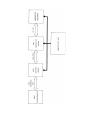
Winchester Disc unit block diagram
Winchester Disc unit parts list
Winchester Disc unit assembly diagram
Winchester Disc unit wiring diagram
LED connection diagram
Winchester Disc Host Adapter parts list
Host Adapter PCB assembly diagram
page
1
2
3
3
3
3
3
4
4
4
5
8
8
9
10
10
12
13
14
14
14
15
15
16
16
17
18
18
19
19
19
20
20
21
21
22
25
27
28
29
31
33
34
35
WARNING: THE WINCHESTER DISC UNIT MUST BE EARTHED
IMPORTANT: The wires in the mains lead for the apparatus are coloured in
accordance with the following code:
GREEN & YELLOW - EARTH
BLUE - NEUTRAL
BROWN - LIVE
As the colours of the wires may not correspond with the coloured markings
identifying the terminals in your plug, proceed as follows:
The wire which is coloured green and yellow must be connected to the terminal
in the plug which is marked by the letter E, or by the safety earth symbol ±
, or coloured either green or green and yellow.
The wire which is coloured blue must be connected to the terminal which is
marked by the letter N, or coloured black.
The wire which is coloured brown must be connected to the terminal which is
marked by the letter L, or coloured red.
If the socket outlet available is not suitable for the plug supplied, the plug
should be cut off and the appropriate plug fitted and wired as previously
noted. The moulded plug which was cut off must be disposed of as it would be
a potential shock hazard if it were to be plugged in with the cut off end of
mains cord exposed.
The moulded plug must be used with the fuse and the fuse carrier firmly in
place. The fuse carrier is of the same basic colour* as the coloured insert in
the base of the plug. Different manufacturers' plugs and fuse carriers are not
interchangeable. In the event of loss of the fuse carrier the moulded plug
MUST NOT be used. Either replace the moulded plug with another conventional
plug wired as previously described, or obtain a replacement fuse carrier from
an Acorn Computers authorised dealer. In the event of the fuse blowing, it
should be replaced, after clearing any faults, with a 5 amp fuse that is ASTA
approved to BS 1362.
*Not necessarily the same shade of that colour.
1. Introduction
This manual is intended to provide the information required to
diagnose and repair faults on the Winchester Disc unit which was
designed by Acorn Computers Limited of Cambridge, England.
The only dealer-serviceable part of the Winchester Disc unit is the
Host Adapter printed circuit board. Faults detected in the disc
drive, disc controller board, or power supply mean that the faulty
part must either be returned for repair or replaced. Dealers may hold
stock of these items and should refer to information provided by their
supplier for service procedures for these units.
The information contained in this manual is aimed at service engineers
and Acorn dealers who will be servicing the Winchester Disc unit on
behalf of Acorn Computers Ltd.
1
2. Packaging and installation
The Winchester Disc unit is supplied fitted with two expanded polyethylene
end pieces in a corrugated card box. Supplied with the Winchester Disc unit
is a User Guide, a ROM labelled ADFS, a mains lead, a 1MHz bus lead and a
guarantee card which are all packed in a card tray located in the top of the
box.
The ADFS ROM must be plugged into one of the host microcomputer's sideways
ROM sockets, or the Winchester filing system will not work.
The Winchester Disc unit must be connected to a 240V AC 50Hz supply via the
mains lead provided and the socket at the rear of the unit.
A mains power switch is located at the rear of the unit.
A 3.15A type F fuse is located in a holder beneath the mains socket at the
rear of the unit.
The Winchester Disc unit must be connected to the host microcomputer's 1MHz
expansion bus socket using the ribbon cable provided.
There is a green activity lamp on the front panel which illuminates when the
drive is being accessed.
The Winchester unit is fragile, and must not be subjected to any shock. Do not
use the unit in conditions of extreme heat, cold, humidity or dust or in
places subject to vibration. Do not block ventilation in front of or behind
the unit, especially the fan intake at the rear. Ensure that no foreign
objects are inserted through any openings in the case. Do not move the unit
while it is operating.
The unit must be transported in its original packing, which must be retained
for future use.
2
3. Specification
The Winchester Disc unit provides storage and retrieval of data and programs
on non-removable magnetic discs. This can be local storage for a
microcomputer such as the BBC Microcomputer model B or as a fileserver for an
ACORN ECONET local area network.
The Winchester Disc unit consists of a 10 Mbyte (model 110) or 30 Mbyte (
model 130) hard disc drive, an ADAPTEC ACB-4000 Winchester Disc Controller,
an Acorn Host Adapter Board which is an interface between the ACB-4000 and the
host computer's 1 MHz expansion bus, and a power supply unit. The unit also
contains a 240V AC fan for cooling.
3.1 Disc drive
Capacity
Format
Cylinders
Heads
Disc rpm
10M (model 110) or 30M (model 130) formatted
ADAPTEC 33 sectors of 256 bytes
306 (10M version)
4 (10M version)
3600
3.2 ADAPTEC ACB-4000 Winchester disc controller
Disc interface ST-412
Host interface SCSI
3.3 Host Adapter
SCSI to 1 MHz expansion bus
3.4 Power supply
Minimum input voltage 198V AC
Maximum input voltage 264V AC
Supply frequency 47 to 53Hz
+5V output voltage 4.9 to 5.2V
+5V output current 0.7 to 3.5A
+5V overvoltage protection 5.8 to 7.0V
+5V overcurrent protection 5.0A
+12V output voltage 11.4 to 12.6V
+12V output current 0.6 to 3.0A
+12V surge output current 5A for 15 seconds
+12V overvoltage protection 13.0 to 16.0V
+12V overcurrent protection 6.0A
3
3.5 Environmental
Minimum
Maximum
Minimum
Maximum
operating temperature
operating temperature
storage temperature
storage temperature
0 degrees C
+37 degrees C
-30 degrees C
+60 degrees C
Maximum operating humidity
Maximum storage humidity
80% RH at 35 degrees C
80% RH at 55 degrees C
Operating altitude
Storage altitude
0 to 1800 metres above sea level
0 to 3500 metres above sea level
Thermal gradient
10 degrees C per hour
Operation lifetime
Mean time before failure
50,000 hours
10,000 hours of typical usage
3.6 Outside dimensions
height 100mm (108mm including feet)
width 335mm
depth 365mm
3.7 Connections
Two 37 way D-type socket connectors are provided for 1MHz bus daisy chain
connection. These are on the rear panel and are labelled '1MHz bus IN' and '
OUT', although they are in fact identical. Three removable resistor packs are
mounted on the Host Adapter PCB inside the case for 1MHz bus termination.
These packs are fitted as standard, but need be retained only in the last
unit in the daisy chain.
Also on the rear panel is an IEC plug for mains power input.
4
4. Disassembly and assembly
Warning: when the Winchester Disc unit is moved or worked upon, great care
must be taken not to drop, jar or shock the unit in any way. If the hard disc
is broken through careless handling then the unit is unserviceable.
i) Ensure that the unit is disconnected from the mains power supply before
dismantling it.
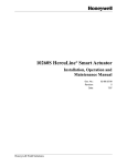
ii) To service the Host Adapter PCB, remove the three small phillips screws
labelled A in figure 1, underneath the front of the unit which hold on the
front panel.
(The unit may be turned on its back to do this if desired, but then remember
that references to left and right in the following description will be
reversed.)
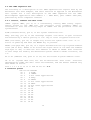
Figure 1 Screws to remove
5
iii)
pull
LED)
note
Insert a hook through the grill on the front panel to the left side and
the front panel until the the connection to the light emitting diode (
is visible. Pull the connector off the light emitting diode and make a
of which way round it was fitted. Remove the front panel completely.
iv) Undo the six small phillips screws labelled B in figure 1, which connect
the bottom panel to the top panel.
(If the unit was turned on its back to gain access to the screws on the
bottom panel, now turn it back the right way up.)
v) Remove the single small phillips screw labelled C in figure 1, from the
rear panel (middle top near the ribbon cable).
vi) Slide the top cover forward and off, being careful not to get any of the
cables or components caught in it. (The lug which was located by the screw in
the rear panel will usually become caught in the internal cabling during this
process.)
vii) The back panel can be left in place.
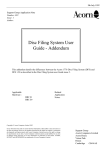
viii) Two PCBs are now visible to the front left of the unit, one above the
other, see figure 2.
Figure 2 View from left side
6
If it is necessary to test the Host Adapter (the lower PCB) with the system
running then the top board can be removed with all its cable connections in
place. Alternatively, the connectors can be unplugged to ease removal of the
board and then reconnected again afterwards.
Remove the top board by undoing the four phillips screws which hold the PCB
on its four plastic pillars. The Host Adapter PCB is the lower board and may
be worked upon without removal. If it is necessary to replace the Host
Adapter PCB then it can be removed in the same way as the top board.
ix) No further disassembly must be carried out. The cover of the hard disc
drive unit must NOT be removed.
Reverse the above procedure to reassemble the unit. Do not forget to
reconnect the LED cable at iii) before relocating the front panel.
Note: the LED connector must be connected the correct way round or the LED
will not function.
7
5. Circuit description
The only part of the Winchester Disc unit which is serviceable by Acorn
dealers is the Host Adapter PCB (see appendix for circuit diagram) and its
connectors and cables etc. This is an interface between the asynchronous SCSI
interface to the disc controller board, and the synchronous 1MHz expansion bus
interface on the host microcomputer used by the Winchester Disc filing
system. The following circuit description will provide enough information
about the disc controller board and the 1MHz expansion bus to allow a full
understanding of the operation of the Host Adapter board. For the full
specification of the SCSI interface see the relevant literature.
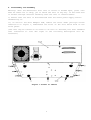
5.1 The disc controller board
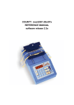
The disc controller used in the Winchester Disc unit is a device which will
send or accept parallel (byte) data to or from the host microcomputer (via
1MHz bus and Host Adapter), and will read or write this data serially to or
from the hard disc. It contains a 256 byte cache memory (hereafter referred to
as the "sector memory" because 1 disc sector = 256 bytes). A connection
diagram for the disc controller board is given in figure 3 below.
Figure 3 Disc controller board connection diagram
8
In the following description, the Host Adapter is known as the "initiator",
and the disc controller is known as the "target".
5.1.1 SCSI control and data lines
The 8 control and 8 data lines on the SCSI side of the controller (shown on
the right side of the Host Adapter circuit diagram in the appendix) are all
active-low open collector, and are as follows:
SELECT (SEL, pin 44) is an open collector signal which is asserted by the
initiator as the first step in any transfer of data through the interface.
BUSY (BSY, pin 36) is an open collector signal which is asserted by the
target to indicate that the data bus is in use. This is the first response of
the target to the initiator's assertion of SEL, and the SEL/BSY handshake is
the first communication in any Winchester filing system operation.
CONTROL/DATA (C/D, pin 46) is asserted by the target when the bus carries
control information, and is deasserted when the bus carries data.
INPUT/OUTPUT (I/O, pin 50) controls the direction of data flow, and is
asserted by the target to indicate input to the initiator (disc to computer),
and is deasserted to indicate output to the target (computer to disc).
REQUEST (REQ, pin 48) is asserted by the target to indicate a request for a
REQ/ACK data transfer handshake.
ACKNOWLEDGE (ACK, pin 38) is asserted by the initiator to indicate
acknowledgement of a REQ/ACK data transfer handshake. The REQ/ACK handshake
provides the asynchronous timing of all data transfer between initiator and
target.
RESET (RST, pin 40) is asserted by the initiator on power-up and when the host
microcomputer's BREAK key is pressed. It causes the "reset condition" (see 5.
1.3) which immediately clears the bus and resets the system.
MESSAGE (MSG, pin 42) is asserted by the target when it issues a message byte
to notify completion of a command, see 5.1.2.
DATA BUS (DB0 to DB7, pins 2 4 6 8 10 12 14 and 16) is a parallel data bus
consisting of 8 signals from DBO (least significant) to DB7 (most significant)
. 1 byte of information is transferred across the bus with each REQ/ACK
handshake. It is important to remember that the data lines are active-low and
therefore are inverted in both directions when communicating with the host
microcomputer.
All odd numbered pins are OV, and pin 34 is +5V.
9
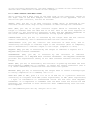
5.1.2 SCSI connector pinout (PL2 and J4)
0V
0V
0V
0V
0V
0V
0V
0V
0V
0V
0V
0V
0V
0V
0V
0V
0V
0V
0V
0V
0V
0V
0V
0V
0V
Pin
1
3
5
7
9
11
13
15
17
19
21
23
25
27
29
31
33
35
37
39
41
43
45
47
49
no
2
4
6
8
10
12
14
16
18
20
22
24
26
28
30
32
34
36
38
40
42
44
46
48
50
DB0
DB1
DB2
DB3
DB4
DB5
DB6
DB7
}
}
}
} For future expansion
}
}
}
}
+5V to supply test equipment
BSY
ACK
RST
MSG
SEL
C/D
REQ
I/O
5.1.3 Bus phases
The bus has several distinct operational phases and cannot be in more than
one of these phases at any given time.
Bus phases occur in a prescribed sequence. The reset condition can interrupt
any phase and is always followed by bus free. Any other phase can also be
followed by the bus free phase.
The prescribed sequence is from bus free to selection to one or more of the
information transfer phases to bus free again.
There are no restrictions on the order of information transfer phases, and a
phase will often follow itself, eg two data phases one after the other.
A typical sequence would be:
bus free
select controller - selection phase
transfer command bytes - command phase
transfer data bytes (if necessary) - data in/out phase
status phase
message phase
10
The phases are as follows:
Bus free phase: indicates that the bus is available for use. The bus free
phase is indicated by all control signals described in section 5.1.1 being
deasserted. If SEL and BSY and RST are not asserted, that is sufficient to
guarantee bus free.
Selection phase: allows the initiator to select the target. After detecting
bus free, the initiator asserts SEL. The target detects SEL asserted, and BSY
and I/O deasserted, and responds by asserting BSY. The initiator deasserts
SEL and may then change the data signals.
Information transfer phases: allow transfer of information across the bus.
There are several different types of information transfer phase, and the type
is determined by MSG, C/D and I/O. Table 1 shows the information transfer
phases:
SIGNALS
MSG C/D I/O PHASE NAME
DIRECTION OF
INFORMATION TRANSFER
1
1
1
1
1
1
0
0
1
0
1
0
data out phase
data in phase
command phase
status phase
initiator
target to
initiator
target to
0
0
0
0
1
0
message out phase
message in phase
initiator to target (not used)
target to initiator
All signals active-low:
to target
initiator
to target
initiator
0=assertion
1=deassertion
Table 1 Information transfer phases
The information transfer phases use the REQ/ACK handshake to control
information transfer: each REQ/ACK allows the transfer of 1 byte. The
handshake sequence is:
1234-
target asserts REQ to request data transfer
initiator asserts ACK when data is valid on bus
target deasserts REQ when data has been transferred
initiator deasserts ACK ready for next handshake
Prior to and during information transfer, the I/O signal determines the
direction of the transfer as can be seen in Table 1.
Before each information transfer phase the target will set up the MSG, C/D and
I/O lines in such a way that these control signals are stable for 450ns before
the REQ of the first handshake, and remain valid until the deassertion of ACK
at the end of the last handshake.
During each information transfer phase the BSY line remains asserted and SEL
deasserted.
11
Each information transfer phase is as follows:
Command phase: allows the initiator to direct the subsequent action of the
target by transferring command bytes. The target asserts C/D and deasserts MSG
and I/O.
Status phase: allows the initiator to read the target's status information.
The target asserts C/D and I/O and deasserts MSG.
Data out phase: allows data to be transferred from initiator to target. The
target deasserts MSG, C/D and I/O.
Data in phase: allows data to be transferred from target to initiator. The
target asserts I/O and deasserts MSG and C/D.
Message out phase: not used by the system - available for future expansion.
Message in phase: allows the target to send a message byte to notify
completion of a command.
5.1.4 The reset condition
The reset condition is caused by the assertion of RST, and immediately clears
the bus and resets the system. Regardless of the prior bus phase, the bus
resets to the bus free phase. The Winchester controller reads the drive's
parameters off the disc.
Reset can occur at any time and takes precedence over all other phases and
conditions. In practice it occurs on power-up or when the BREAK key is
pressed.
12
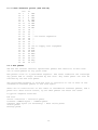
5.1.5 The ST-412 disc interface connector pinouts (J2 and JO)
The disc controller board communicates with the Winchester disc via two
connectors: J2 carries control information, and J0 carries data. J1 is not
used in this implementation, but is electrically identical to J0.
J2
0V
0V
0V
0V
0V
0V
0V
0V
0V
0V
0V
0V
0V
0V
Pin no
1
2
3
4
5
6
7
8
11
12
13
14
17
18
21
22
23
24
25
26
27
28
29
30
31
32
33
34
READ/WRITE CURRENT
HEAD SELECT 2^2
WRITE GATE
SEEK COMPLETE 0V 9
WRITE FAULT
HEAD SELECT 2^0 0V
HEAD SELECT 2^1 0V
READY
STEP
DRIVE SELECT 1
DRIVE SELECT 2
DRIVE SELECT 3
DRIVE SELECT 4
DIRECTION IN
HEAD 2^3
10 TRACK 0
15 16 RESERVED
19 20 INDEX
J0 Pin no
DRIVE SELECTED
1
2 0V
RESERVED
3
4 0V
RESERVED
5
6 0V
RESERVED
7
8 0V
RESERVED
9
10 RESERVED
0V 11
12 0V
+MFM WRITE DATA 13
14 -MFM WRITE DATA
0V 15
16 0V
+MFM READ DATA
17
18 -MFM READ DATA
0V 19
20 0V
The read and write MFM data lines (pins 13 14 17 and 18 of J0) are
differential signals.
13
5.2 The 1MHz expansion bus
The following is a description of the 1MHz expansion bus signals used by the
Winchester Disc Host Adapter, and their function as applied to the Winchester
Disc system. For a full description of the 1MHz expansion bus see "BBC
Microcomputer Application Note Number 1 - 1MHz Bus", part number 0407,000,
published by Acorn Computers Limited.
5.2.1 Control, address and data lines
1MHzE (system 1MHz, pin 4) is a continuously running 1MHz timing signal.
During access to the 1MHz bus, the processor clock (normally 2MHz) is
stretched so that the trailing edges of 1MHzE and the processor clock are
synchronised.
R/NW (read/not-write, pin 2) is the system read/write line.
NIRQ (not-IRQ, pin 8) is the interrupt request line which is open collector
and asserted by a device pulling it low. IRQ is level triggered active-low.
NRST (not-reset, pin 14) is output only active-low system reset line. It is
active on power-up and when the BREAK key is pressed.
NPGFC (not-page &FC, pin 10) is a signal decoded from the top 8 system address
lines (A8 to A15). NPGFC is an active-low signal which is low when the address
high byte is &FC, ie when the full address is &FC00 to &FCFF. Four locations
in this range are used by the Winchester system: &FC40 to &FC43 inclusive, see
7.2.
A0 to A7 (address low, pins 27 to 34) are the bottom 8 system address lines.
D0 to D7 (system data bus) are the bi-directional data lines. Direction
determined by R/NW. The data lines are buffered, and the buffer enabled only
when NPGFC is active.
Pins 1 3 5 7 9 11 13 15 17 and 26 are 0V. 5.2.
2 Connector pinout
TOP Pin No BOTTOM
0V 1
2 R/NW
0V 3
4 1MHzE
0V 5
6 For other applications
0V 7
8 NIRQ
0V 9
10 NPGFC
0V 11 12 For other applications
0V 13 14 NRST
0V 15 16 For other applications
0V 17 18 D0
D1 19 20 D2
D3 21 22 D4
D5 23 24 D6
D7 25 26 0V
A0 27 28 Al
A2 29 30 A3
A4 31 32 A5
A6 33 34 A7
14
5.3 Winchester Disc Host Adapter
In conjunction with the following description, reference should be made to the
Winchester Disc Host Adapter circuit diagram in the Appendix.
The Winchester Disc Host Adapter is an interface between the SASI/SCSI
interface and the 1MHz expansion bus. It consists of address decoding and
handshake control, buffering of the signals in either direction, and
termination.
5.3.1 Address decoding and handshaking
The Host Adapter decodes 4 locations in the host microcomputer's page FC I/O
space. These four locations are as follows:
Address
&FC4O
&FC41
&FC42
&FC43
Read Write
data data (direction determined by R/NW)
status --select
enable IRQ
Page FC is decoded in the host microcomputer and this is available to the Host
Adapter as NPGFC (not-page FC). NPGFC is synchronised with 1MHzE by the deglitch circuit (half of IC10) and the clean signal is labelled CNPGFC (pin 5,
IC10).
The low order address lines A0 to A7 are buffered through IC5.
IC6, a 3 to 8 line decoder with three enable inputs, decodes the low order
addresses &4O to &43, ie output pin 15 goes low when the low order address is
&40, &41, &42 or &43.
IC7 is another 3 to 8 line decoder which takes the output from IC6 and CNPGFC
and 1MHzE as enable inputs. The 2 least significant address bits A0 and Al are
decoded along with R/NW into the required 5 separate signals shown above.
Y0
Y4
Y1
Y6
Y7
(pin
(pin
(pin
(pin
(pin
15) is read data (R/NW = 1)
11) is write data (R/NW = 0)
14) is status
9) is select
7) is enable IRQ
All these outputs are active-low.
When either of the two data transfer paths is selected (Y0 or Y4) an ACK
signal is generated by clocking a D-type flip-flop (half of IC11). This flipflop is cleared direct from the REQ line, and thus the REQ/ACK handshake is
facilitated.
The other half of IC11 facilitates the SEL/BSY handshake. The D-type is
clocked by Y6 to generate select and is cleared by BSY.
When Y7 is selected, the least significant bit on the data bus (D0) is clocked
into a D-type flip-flop (half of IC10). If this value is a 1 then the latch (2
NANDs of IC12) is enabled and an IRQ will be generated at the next falling
edge of REQ. To disable interrupts Y7 is
selected with a 0 on D0. IRQs are enabled only for a very short time (around
10ms) when ensuring a sequential file buffer.
15
5.3.2 Buffering
The data bus (D0 to D7 of host microcomputer, DB0 to DB7 of SCSI interface) is
buffered in the write direction by an octal 3-state buffer IC1 and an octal
transparent latch (IC2). IC2 is enabled by Y4 of IC7 which is the write data
signal, see 5.3.1. Because IC2 is a transparent latch, data will remain valid
on the output side when the enable is deasserted. The outputs from IC2 are
gated through 8 open collector NAND buffers which are enabled from the I/O
control line of the SCSI interface and which invert the bus signals. To write
data across the Host Adapter requires that both R/NW = 0 and I/O = 1.
The data bus is buffered and inverted in the read direction by an octal 3state inverting buffer which is enabled by Y0 of IC7 which is the read data
signal, see 5.3.1.
The control signals used by the SCSI interface are available for reading by
the host microcomputer. They can be latched into IC4, an octal transparent
latch, when it is enabled by Y1 of IC7. The control signals appear on the data
bus in the following positions:
D0
Dl
D2
D3
D4
D5
D6
D7
MSG
BSY
0
0
NIRQ (see 5.3.1)
REQ
I/O
C/D
All these control signals are inverted either by IC15 or IC9 prior to being
latched, so all values read from the data bus are active high.
5.3.3 Termination
The Host Adapter PCB carries 4 resistor packs, RP1 to RP4, which are used
for terminating the various buses and control lines.
RP1 terminates the SCSI lines from the disc controller board.
RP2, RP3, and RP4 terminate the 1MHz bus lines and are fitted if the
Winchester is the only peripheral on the 1MHz bus or if it is the last
peripheral in a daisy-chain.
16
6 Test equipment and formatting
Test Equipment Required:
BBC Microcomputer model BD ("host microcomputer"), fitted with ADFS ROM.
Video Monitor
Floppy Disc Drive (see below)
Winchester Disc unit Under Test
6.2 Formatting Drives
Before shipment, each Winchester Disc unit has a suite of utility programs
stored on it, including a formatter entitled "Superform". Copies of this
software are available to dealers on floppy disc.
For details on formatting, see the Winchester Disc User Guide, Acorn Part No.
0427,000.
Not explained in the User Guide are options B and C. Affixed to the drive
itself is a label or labels bearing the defect list and other parameters
particular to that drive.
Option B is used to input the defect list from the label in head, cylinder,
byte format.
Option C is for entering the drive's parameters such as number of heads,
cylinders, etc.
These options would be used for formatting a new drive or re-formatting a
drive which lacks a readable parameter or defect list for any reason.
When Superform is run, it tries to read the defect list and parameter list
from the drive and, if successful, it automatically formats the drive using
this information. Built into Superform is a set of default values for drive
parameters which can be inspected using
option C. If the drive concerned differs in any respect, the parameters must
be typed in again. Two common classes of difference are:
1 On a 10M drive, RWCC could be 306 or 128.
2 On a 30M drive, the parameters for heads, cylinders and RWCC will differ
All data stored on the Winchester Disc, including the utility programs, are
lost after formatting.
17
7 Fault finding
When the Winchester Disc unit is powered-up, the hard disc will spin up to
speed in about 10 seconds. This process produces a rising pitch humming noise
which means that the hard disc is spinning. Note that there is also a noise
from the cooling fan, but this noise is lower in pitch and does not take time
to build up. If the disc is not spinning then disassemble the unit and check
the power supply and connections.
Make sure that the ADFS ROM is plugged into one of the test BBC
Microcomputer's sideways ROM sockets. If the machine will not access the
Winchester then type
*ADFS
If the unit powers up correctly but still won't work then print out the
contents of the status register as follows:
PRINT ~?&FC41
The result should be zero. If the result is FF then the ribbon cable is
disconnected.
7.1 Power supply
The three major components of the Winchester Disc unit - the disc drive, the
disc controller board, and the Host Adapter board - are each powered from the
switch-mode power supply unit which sits at the back left of the case. The
power supply output cables are colour coded as follows:
black ground
red
+5V
yellow +12V
The power supply can be tested by measuring the +5 voltage between the black
and red cables, and the +12 voltage between the black and yellow cables. The
allowable voltage ranges are as follows:
+5V (black and red)
+12V (black and yellow)
4.9V to 5.2V
11.4V to 12.6V
These measurements should be made with all connectors in place.
Next measure the current drawn by each of the three components specified above
from the +5V and +12V supplies. Two of the components are each supplied via a
four-way plug-in connector, and the current measurement should be made in
series with either the red cable (+5V) or the yellow cable (+12V). The
connections to the meter to do this must be made with the power switch off.
The measurements must be made after power-up as some of the circuitry, when
working correctly, will alter its current consumption with time as shown
below. The current drawn by each component from each voltage rail should be as
follows:
Winchester hard disc unit, see figure 2:
+5V around 1 to 1.5A
+12V up to 4.5A on power-on falling to around 2A when up to speed
18
Disc controller board, see figure 2:
+5V around 1.5A
+12V around 250mA
Host Adapter board, see figure 2:
+5V around 500mA
+12V zero (not used)
The above figures are approximate and will enable checks to be made for
open/short circuits and malfunctioning components.
7.2 Address decoding
The easiest way to test the address decoding is to execute a program which
accesses the relevant memory location.
7.2.1 &FC40 read data
Run the following program:
10DIM P% 10
20[
30.a
40LDA &FC40
50JMP a
60]
70CALL a
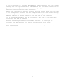
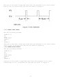
Test pin 1 IC3 with a scope and check that the waveform is not stuck either
high or low. It should look like the one shown in figure 4.
7.2.2 &FC40 write data
Run the following program:
10DIM P% 10
20[
30.a
40STA &FC40
50JMP a
60]
70CALL a
19
Test pin 11 IC2 with a scope and check that the waveform is not stuck either
high or low. It should look like the one shown in figure 5.
7.2.3 &FC41 read status
Run the following program:
10DIM P% 10
20[
30.a
40LDA &FC41
50JMP a
60]
70CALL a
Test pin 1 IC4 with a scope and check that the waveform is not stuck either
high or low. It should look like the one shown in figure 4.
7.2.4 &FC42 write select
Run the following program:
10DIM P% 10
20(
30.a
40STA &FC42
50JMP a
60]
70CALL a
Test pin 11 IC11 with a scope and check that the waveform is not stuck
either high or low. It should look like the one shown in figure 4.
20
7.2.5 &FC43 write IRQ enable
Run the following program:
10DIM P% 10
201
30.a
40LDA# 0
50.b
60STA &FC43
70JMP b
80]
90CALL a
Test pin 11 IC10 with a scope and check that the waveform is not stuck
either high or low. It should look like the one shown in figure 4.
Pin 9 IC10 should be logic 0.
Now run the following program:
10DIM P% 10
20[
30.a
40LDA# 1
50.b
60STA &FC43
70JMP b
80]
90CALL a
and pin 9 IC10 should now be logic 1.
7.3 Handshaking
To test the SEL/BSY handshake use the following program:
10DIM P% 20
20[
30.a
40LDA# 1
50STA &FC40
60STA &FC42
70.b
80LDA &FC41
90BEQ b
100RTS
110]
120PRINT ~USR(a) AND &FF
Press the BREAK key followed by OLD and RUN the program. The LED on the disc
controller board should illuminate, and the result 2 should be printed on the
screen after the assembler listing. (The result is the contents of the status
register, and BSY is bit Dl which corresponds to 2.)
If nothing happens and the program is typed in correctly then there is
either a loose connection or a fault in the disc controller board.
The system can be deselected by pressing BREAK.
21
The REQ/ACK handshake operates only during data transfer. If the hardware for
this handshake is faulty then there can be no data transfer.
7.4 Bus lines
When the buses are not being asserted either by the SCSI interface or the host
microcomputer, ie in the bus free phase, all bus lines will float according to
the values of their terminating resistors.
Measure the voltage of each bus line in turn and make sure that none of them
is stuck at +5V, which would indicate a short circuit, or at 0V which would
indicate either that one of the buffers was enabled or that there was a short
circuit. The correct voltages are as follows:
1 MHz expansion bus D0 to D7 and A0 to A7 should all be 2.5V.
SCSI DB0 to DB7 should all be 3V.
If, for example, D0 to D7 are all 0V or a mixture of 0V and 2.5V then one of
the buffers is probably enabled.
22
APPENDIX
23
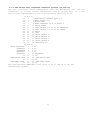
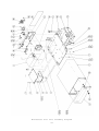
Winchester Disc Unit parts list -SEE PAGE 29
Item Part No
Description
Qty
1
*0201,580 case (base)
1
2
*0201,581 case (top)
1
3
*0201,582 case (rear)
1
4
*0201,583 110 front panel screened 1
*0201,524 130 front panel screened 1
5
6
0830,053
disc drive
1
~0831.107 disc drive
1
7
~0831,102 power supply
1
8
~0837,000 PCB (controller)
1
9
0127,000
PCB (host adapter)
1
10
11
0890,010
adhesive silicone rubber a/r
12
*0884,054 PCB support spacer
4
13
*0884,053 PCB support spacer
4
14
*0882,121 screws M3x6 pan hd posi
8
15
*0884,140 screws 6-32 uncx3/8 pan hd 4
16
*0884,160 washers 6-32 UNC
4
17
*0882,974 washers M4
8
18
*0882,124 screws M3x12 pan hd posi 4
19
*0201,587 rear label
1
20
*0201,586 front label
1
21
*0882,223 screws M3x10 csk hd posi 2
22
*0890,000 rubber feet
4
23
*0805,003 switch dpst 250V 10A
1
24
*0882,121 screws M3x6 pan hd posi
13
25
*0815,902 power socket
1
26
*0800,983 conr skt jk kit
2
27
*0882,972 washers M3
35
28
*0882,902 nuts M3
2
29
*0815,222 fuse 3A15 F HBC 20x5mmD
30
*0880,072 cable clamp
31
*0201,921 fan
32
*0882,144 screws M4x12 pan hd posi
33
34
*0882,904 nuts M4
35
*0885,201 fan finger guard
36
*0779,006 stackable LED
37
*0779,005 grmt
38
*0201,700 cable assy
39
*0201,701 cable assy
40
*0201,702 cable assy
41
*0201,703 cable assy
42
*0201,704 cable assy
43
*0880,101 cable tie 197mm
44
*0201,706 cable assy
45
*0201,707 cable assy
46
*0201,732 cable assy
47
48
*0201,734 cable assy
49
*0201,877 cable assy
Parts marked * are available as spares;
parts marked ~ can be obtained for dealers
Contact supplier for details.
28
2
2
1
4
Remarks
10M version
30M version
10M version
30M version
for
for
for
for
for
PCB spacers
disc drive
disc drive
fan and earth
psu mounting
for power socket
for case assy
for power socket and
37-way conns
for item 25
for fan
6
1
1
1
1
1
1
1
1
6
1
1
1
for fan and earth
1
1
ha to 1MHz bus
LED to Winchester
for item 36
live jumper
live jumper
neutral jumper
safety earth
disc drive earth
drive data
drive control
ha to controller
by their supplier.
Winchester Disc unit assembly diagram
29
Winchester Disc unit wiring diagram
31
LED connection diagram
33
Winchester Disc Host Adapter parts list -SEE PAGE 35
Item Part No
Description
Qty Remarks
1
bare PCB
1
2
3
4
0502,222
resistor 2k2 .25W +/- 5%
1
R1
5
*0572,221
resistor pack 16 pin DIL 220R/330R 1
RP1
6
*0573,222
resistor pack 16 pin DIL 2k2
2
RP2,RP3
7
*0571,222
resistor pack 16 pin DIL 2k2
1
RP4
8
*0800,116
IC socket 16 pin
3
RP2,3,4
9
10
0680,002
capacitor decoupler 47nF
16 A
11
0622,220
capacitor 22uF 16V
1
C2
12
13
14
15
*0740,007
7407
1
IC16
16
*0740,014
7414
1
IC15
17
*0740,038
7438
2
1C13,1C14
18
*0742,000
74LS00
1
IC12
19
*0742,004
74LS04
1
IC9
20
*0742,014
74LS14
1
IC8
21
*0742,074
74LS74
2
IC10,IC11
22
*0742,138
74LS138
2
106,1C7
23
*0742,240
74LS240
1
IC3
24
*0742,244
74LS244
2
IC1,IC5
25
*0742,373
74LS373
2
1C2,1C4
26
27
28
*0800,870
connector 34 pin header
1
PL1
29
*0800,871
connector 50 pin header
1
PL2
30
31
32
*0800,784
right angle faston tab
2
0V,5V
Parts marked * are available as spares. Contact supplier for details.
34
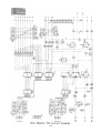
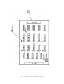
Host Adapter PCB assembly diagram
35