1
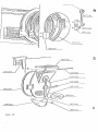
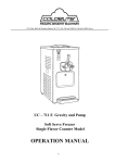
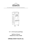
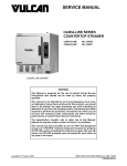
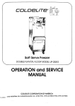
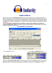
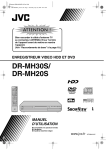
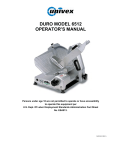
Batch Freezer
MODELS LB-250/LB-500/LB-4000/LB-500G/LB-1000G
I
OPERATION and SE
ANUAL
C O R P O R A T I O N
.
O F
A M E R I C A
-
P.O. Box 4069
Winston-Salem, NC 271 15
3760 Industrial Drive
Winston-Salem. NC 27105
Telephone: (919) 661 -9893 Telefax: (919) 661 -9895 Telex: 7541 70
F O R E W O R D
Thank you for selecting COLDELITE to meet today's fast
growing demands. Your COLDELITE freezer has been manufactured at the most modern freezer manufacturing plant
in the U.S.A., our Lodi, New Jersey facility, utilizing
the most advanced equipment and technology available in
the industry. We, at COLDELITE, take great pride and
care in the manufacture of each and every freezer, using
only the finest components available, to provide you with
years of trouble-free operation.
Over twenty-five years of experience in the manufacturing
of dispensing equipment have guided us in the preparation
of this Operation and Service Manual. PLEASE READ IT
CAREFULLY. Keep it for future reference and most of all,
follow the instructions from the very time your machine
is delivered.
On the following pages, you will find important information and procedures which describe the proper installation,
sanitizing, operation and maintenance of your COLDELITE
machine. We feel certain that your full compliance with
these instructions wili assure you of excellent performance,
trouble-free operation and a profitable business for years
to come.
N O T I C E
Failure to closely follow set-up and maintenance procedures,
can void your warranty. Coldelite Corporation will not be
responsible for any machine not properly maintained.
W A R N I N G
EXTREME CARE MUST BE TAKEN WHZN REMOVING SIDE,
REAR OR CONTROL BOX PANELS.
ALWAYS TURN THE SELECTOR SWITCH TO THE OFF
POSITION. ALSO TURN OFF THE DISCONNECTSWITCH ON ELECTRICAL SUPPLY LINE BEFORE
EXPOSING ANY ELECTRICAL CONNECTIONS AND/OR
MOVING PARTS, SUCH AS BELTS, PULLEYS, FAN
BLADES AND BEATER.
BATCH ICE CFEAM FREEZERS
MODELS LB-250
LB-500G
PART I
-
-
-
500
1000
LB-1000G
I N S T A L L A T I O N
UNCRATING
B e f o r e s t a r t i n g t h i s p r o c e d u r e , make s u r e t h e c a r t o n d o e s n o t
show e v i d e n c e o f h a v i n g b e e n d r o p p e d , tampered w i t h o r a b u s e d
i n s u c h a way a s t o i n d i c a t e t h a t i t s c o n t e n t s may h a v e b e e n
damaged i n t r a n s i t .
-
IMPORTANT
I n t h e e v e n t t h e o u t s i d e of t h e c r a t e should give
any i n d i c a t i o n o f p o s s i b l e h i d d e n damage, s o s t a t e on t h e B i l l
of Lading b e f o r e s i g n i n g .
C o n t a c t t h e c a r r i e r immediately and
r e q u e s t a n i n s p e c t i o n o f t h e damage. You, t h e c u s t o m e r , m u s t
p l a c e a n y c l a i m f o r damage a n d / o r s h o r t a g e i n s h i p m e n t w i t h t h e
carrier.
C o l d e l i t e C o r p o r a t i o n c a n n o t make any c l a i m a g a i n s t
the carrier.
1) P r o c e e d t o u n p a c k , a s f o l l o w s :
Remove t h e s t r a p p i n g . When you c u t t h i s s t r a p p i n g , d o i t w i t h
c a u t i o n as i t may s n a p o u t .
L i f t t h e c a r t o n s t r a i g h t up and
away f r o m t h e f r e e z e r .
Remove t h e s i d e p a n e l s by l i f t i n g a n d
p u l l i n g o u t from t h e bottom.
Remove t h e b o l t s h o l d i n g t h e
f r e e z e r t o t h e s k i d . Now, c a r e f u l l y , i n s t a l l t h e c a s t e r s o r
legs, while keeping t h e f r e e z e r i n an upright position.
In
some c a s e s , i n s t a l l a t i o n o f t h e c a s t e r s may n o t b e n e c e s s a r y
a s t h e y are p a r t o f t h e frame.
You a r e now r e a d y t o move t h e
machine t o t h e p o i n t o f i n s t a l l a t i o n . ,
2 ) I n s i d e t h e f r e e z e r c a b i n e t , o n t h e l e f t s i d e , when f a c i n g
t h e f r o n t of the m a c h i n e , you w i l l f i n d a 4'x4" e l e c t r i c j u n c t i o n box.
The e l e c t r i c a l c o n n e c t i o n from y o u r c u t - o u t box o r
f u s e box i s made t o t h i s j u n c t i o n box. The e l e c t r i c i a n d o e s
n o t h a v e t o g o i n t o t h e u n i t ' s c o n t r o l box.
(See a d d i t i o n a l
d e t a i l s u n d e r E l e c t r i c a l C o n n e c t i o n s , P a r a g r a p h B.)
3 ) Water c o o l e d m o d e l s w i l l h a v e t w o , 1/2" male p i p e t h r e a d
f i t t i n g s e x t e n d i n g o u t t h e r e a r p a n e l , marked 'Water I n l e t '
a n d ''Water O u t l e t ' , c o n n e c t a c c o r d i n g l y .
(For a d d i t i o n a l
d e t a i l s , r e f e r t o Plumbing C o n n e c t i o n s , P a r a g r a p h C.)
Page 2
5 ) A i r cooled m o d e l s , remove t h e c a r d b o a r d p r o t e c t i o n from
t h e rear.
T h e A I R FLOW IS FROM FRONT TO BACK
a n d t h e r e m u s t b e a minimum o f 1 2 inches of o p e n a r e a b e h i n d t h e
freezer.
N o t e : Fai!ure t o p r o v i d e a d e q u a t e v e n t i l a t i o n w i l l r e s u l t i n
poor p e r f o r m a n c e a n d w i l l v o l d y o u r w a r r a n t y .
tlie condenser a t
_
I
L
6 ) T h e sorllpressor may be e i t h e r b l o c k e d o r b o l t e d down.
When
B e f o r e operating, r e n i o v c t h e b l o c k s o r l o o s e n t h e n u t s .
this i s d o n e , t h e c o m p r e s s o r s h o u l d ' f l o a t ' f r e e l y o n i t s mounting sprlng.
r-
7 ) A l s o be sgre t o r e m o v e
t h e b l o c k from t h e b e a t e r
m o t o r a s t h i s i s c n l y for
shipment.
I f y c u r machine 1 s t h r e e
p h a s e , r o t a t i o n of b e a t e r
m u s t b e c h e c k e d when t h e
e l e c t r i c i a n h a s made h i s
A l l batch
connection.
f r e e z e r s run c o u n t e r clockw i s e when f a c i n g t h e
(See i l l u s t r a t i o n . )
machine.
B)
E L E C T R I C A L CONNECTIONS:
-
Wiring should be m a d e i n accordance with t h e National E l e c t r i c a l
Codes, r u l e s and r e g u l a t i o n s .
M I N I M U M ELECTRICAL REOUIREMENTS
WIRE GAUGE
--.--
POWER SUPPLY musiz be a d e q u a t e t o meet r e q u i r e m e n t s a t a l l t i m e s .
W i t h t h e m a c h i n e l n o p e r a t i o n , v o l t a g e f l u c t u a t i o n s should n o t
.$ e x c e e d 2 1 0 % o f t h e n o r m a l o r r a t e d v o l t a g e .
B e s u r e t o check
Page 3
f o r c o r r e c t v o l t a g e a t t h e f u s e box before t u r n i n g on your
machine.
ADEQUATE K I R I N G s l r o u l d b e p r o v i d e d w i t h r e g a r d t o w i r e s i z e o r
gauge.
U n l e s s o t h e r w i s e r e q u i r e d by t h e l o c a l E l e c t r i c a l C o d e ,
t h e w i r e g a u g e a t t h e m a c h i n e j u n c t i o n box s h o u l d be u s e d f o r
S e e chart on Page 3 .
h separate cirt h e d i r e c t power l i n e .
c u i t b r e a k e r , w i t h a d e q u a t e f u s e p r o t e c t i o n , s h o u l d b e employed.
An u n f u s e d d i s c o n n e c t s w i t c h o r p r o p e r size p l u g - i n ,
the freezer,
close t o
i s recommended.
COLDELITE f r e e z e r s p r o v i d e p r o t e c t i o n f o r the b e a t e r m o t o r .
Should t h e l i n e v o l t a g e d r o p or i f there i s a s h o r t c i r c u i t , t h e
overload p r o t e c t o r w i l l a u t o m a t i c a l l y disconnect t h e s t a r t e r and
t h e m a c h i n e w i l l s t o p i m m e d i a t e l y s o t h a t no p e r m a n e n t damage c a n
be c a u s e d t o t h e m o t o r .
To s t a r t t h e f r e e z e r a g a i n , w a i t a p p r o x i m a t e l y o n e t o t w o m i n u t e s , t h e n p u s h t h e RESET b u t t o n l o c a t e d i n
t h e l e f t p a n e l o f t h e machine.
The compressor i s a l s o i n t e r n a l l y
I f t h e Klixon p r o t e c t o r t r i p s due t o a n o v e r l o a d ,
protected.
t h i s K l i x o n a u t o m a t i c a l l y r e s e t s a n d t h e c o m p r e s s o r w i l l be r e activated.
ROTATION - N e v e r r e v e r s e t h e r o t a t i o n by c h a n g i n g t h e c o n n e c t i o n s
If t h e rotation is not counter clockwise,
i n s i d e t h e s t a r t e r box.
i n t e r c h a n g e t h e w i r e c o n n e c t i o n s b e t w e e n two o f t h e t h r e e l e g s
( p h a s e s ) i n s i d e t h e j u n c t i o n box.
NOTE: I N ALL INSTALLATIONS, BOTH SINGLE AND THREE PHASE, THE
SlNCE ALL ELECTRICAL COMPOMACHINE MUST B E PROPERLY GROUNDED.
NENTS ARE CONNECTED BY MEANS O F FLEXIBLE CONDUIT, ADEQUATE
GROUND CONTINUITY I S ASSURED BY R U N N I N G AND FASTENING A G R O U N D
LINE TO THE MACHINE JUNCTION BOX..
C ) P L U M B I N G CONNECTIONS
On w a t e r c o o l e d m a c h i n e s , y o u w i l l f i n d a 1 / 2 " m a l e p i p e t h r e a d
f i t t i n g , m a r k e d ' W a t e r I n l e t ' a n d o n e , marked ' W a t e r O u t l e t ' .
The c o l d w a t e r l i n e i s c o n n e c t e d t o t h e 'Water I n l e t ' a n d t h e
' W a t e r O u t l e t ' m u s t r u n t o a drain. The d r a i n l i n e i s u n d e r
The
.
p r e s s u r e so t h e w a t e r c a n f l o w upwards, i f necessary.
w a t e r p r e s s u r e a t t h e machine s h o u l d be 60 l b s . p . s . i .
The
If
t e m p e r a t u r e o f t h e w a t e r s h o u l d n o t e x c e e d 68°F ( 2 0 ° C ) .
h o s e s a r e u s e d f o r t h e c o n n e c t i o n , t h e y m u s t be h i g h p r e s s u r e
rated.
WATER VALVE ADJUSTMENT - T h e w a t e r v a l v e s h o u l d b e s e t s o that
men
t h e w a t e r r u n s o n l y when t h e c o m p r e s s o r i s i n o p e r a t i o n .
t h e machine 3s r u n n i n g , t h e d r a i n w a t e r s h o u l d be lukewarm.
Page 4
- I n s o m e a r e a s of t h e c o u n t r y , a n ' a n t i s y p h o n i n g ' or ' a n t i - b a c k ' f l o w v a l v e i s r e q u i r e d o n m a c h i n e s
w i t h a water c o o l e d c o n d e n s e r .
BACK FLOW VALVE
The p u r p o s e of t h i s v a l v e is t o p r e v e n t w a t e r i n s i d e t h e
m a c h i n e ' s c o n d e n s e r from b e i n g drawn i n t o t h e water s u p p l y
l i n e i n t h e e v e n t a v a c u u m c o n d i t i o n o c c u r s i n the s u p p l y l i n e .
Check y o u r local p l u m b i n g c o d e s t o determine i f t h i s v a l v e i s
r e q u i r e d , a n d if s o , h a v e a p l u m b e r i n s t a l l ~t o u t s i d e t h e
unit.
W A R N I N G
Never l e a v e t h e f r e e z e r a t a n ambient temperature lower t h a n
32OF ( 0 ° C ) w i t h o u t d r a i n i n g t h e w a t e r f r o m t h e c o n d e n s e r ,
To d r a i n w a t e r c o m p l e t e l y , o p e n w a t e r v a l v e b y r a i s i n g t h e
s e a t a n d a p p l y a i r p r e s s u r e t o t h e 'Water I n t a k e ' l i n e .
Page 5
EXPLANATION OF ELECTRICAL CONTROLS
PART I I
T h e COLDELITE b a t c h f r e e z e r i s e q u i p p e d w i t h two p r i m a r y
switches:
- T h i s s w i t c h h a s t h e t o t a l c o n t r o l of t h e
m a c h i n e a n d c o n s i s t s o f f o u r p o s i t i o n s , which a r e , a s f o l l o w s :
a) SELECTOR SWITCH
OFF
PRODUCTION
EXTRACTION
-
-
Machine i s completely o f f
B e a t e r motor and compressor a r e running
a u t o m a t i c a l l y and t h e c o m p r e s s o r w i l l b e
t u r n e d o n a n d o f f by t h e H a r d - 0 - M a t i c .
NOTE: On t h e LB-500 a n d LB-1000,
i s r u n n i n g on h i g h s p e e d .
the beater
On t h e LB-500G a n d t h e LB-1000G,
i s r u n n i n g a t low s p e e d .
the beater
Only t h e b e a t e r runs.
The c o m p r e s s o r i s o f f .
T h i s p o s i t i o n i s used a t t h e completion o f
t h e b a t c h t o whip i n a i r and t h e n d i s p e n s e
t h e product.
NOTE: On t h e LB-500, LB-1000, LB-500G a n d
LB-1000G, t h e b e a t e r r u n s a t h i g h s p e e d .
CLEANING
b ) TIMER
-
-
Used f o r a l l c l e a n i n g a n d s a n i t i z i n g o p e r a tions.
The c o m p r e s s o r i s o f f .
T h i s s w i t c h i s t o a s s i s t you i n t i m i n g t h e f r e e z i n g
of a b a t c h .
G e n e r a l l y 10 t o 1 2 m i n u t e s i s t h e normal
H o w e v e r , t h e f i r s t b a t c h may t a k e u p t o
cycle time.
15 minutes.
I t i s recommended t h a t t h e i n i t i a l b a t c h
be s e t a t 1 5 m i n u t e s a n d reset a t 1 2 m i n u t e s f o r s u b sequent batches.
The d u r a t i o n o f b a t c h e s may v a r y w i t h t h e m i x e s o r
flavors used.
When t h e t i m e r r e t u r n s t o z e r o , a b e l l w i l l s o u n d a n d
t h e b a t C h s h o u l d b e f i n i s h e d . To s t o p t h e b e l l , t u r n
t h e s e l e c t o r s w i t c h t o EXTRACTION.
Timer o p e r a t e s o n l y
i n PRODUCTION p o s i t i o n .
See f o l l o w i n g page.
Page 6
TIMER
-
SELECTOR SWITCH
SELECTOR S W I T C H
CLEAN-OUT
Page 7
PART I11
CLEANING AND OPERATION INSTRUCTIONS
T h i s i s a new f r e e z e r a n d b e f o r e making a p r o d u c t , i t m u s t
be c a r e f u l l y w a s h e d a n d s a n i t i z e d , a s f o l l o w s :
a ) Remove t h e d o o r a s s e m b l y b y l o o s e n i n g t h e l o c k i n g b o l t .
Swing t h e d o o r t o t h e l e f t a n d l i f t i t o f f t h e h i n g e p i n .
Remove t h e d i s p e n s i n g g a t e , h a n d l e and h a n d k n o b , o r o n
l a t e r models, t h e e c c e n t r i c p l a s t i c handle.
Remove t h e
b e a t e r from t h e cylinder.
Be s u r e t h e r e a r s e a l comes o u t
I f i t r e m a i n s o n t h e b a c k p l a t e , remove
w i t h t h e beater.
i t . T a k e a l l p a r t s t o t h e s i n k a n d wash them t h o r o u g h l y
Rinse p a r t s and r e t u r n t o machine.
w i t h a mild soap.
L u b r i c a t e t h e r e a r s e a l l i b e r a l l y t o i n s u r e no leakage
I f you n o t i c e m i x i n t h e r e a r d r i p p a n ,
from t h e rear.
WARNING! DO NOT OPERATE THE MACHINE WITH THE FRONT DOOR
REMOVED OR OPEN! DO NOT REMOVE THE PROTECTIVE
GRILL!
Page 8
P??
c h e c k t h e c o n d i t i o n of t h e s e a l .
Replace, i f n e c e s s a r y .
L u b r i c a t e t h e head g a s k e t very l i g h t l y .
\\,r
b) Reassemble t h e f r e e z e r w i t h t h e door a s s e m b l y f i r m l y l o c k e d
i n p l a c e and s l i d e t h e b o l t t i g h t .
Be s u r e t h a t t h e p i n (P) i s
e n e r g i z i n g t h e micro s w i t c h C o d c 1720250 b e h i n d t h e f r o n t p a n e l
( s e e P a g e 1 9 ) . You a r e now r e a d y t o s a n i t i z e t h e f r e e z e r .
C ) Make a S t e r a - S h e e n s o l u t i o n o r e q u i v a l e n t
( c h l o r i n e 200 p p m ) ,
o n e g a l l o n f o r t h e LB-250, two g a l l o n s f o r t h e LB-500 and
LB-1000.
Pour s o l u t i o n i n t o t h e c y l i n d e r and c l o s e t h e c h u t e
cover.
T u r n t h e s e l e c t o r s w i t c h t o CLEAN-OUT a n d a l l o w t h e
m a c h i n e t o r u n f o r 30 t o 40 s e c o n d s .
d ) The s o l u t i o n h a s now b e e n i n c o n t a c t w i t h a l l o f t h e p r o d u c t
z o n e p a r t s ( p a r t s t h a t w i l l b e i n c o n t a c t w i t h t h e mix p r o d u c t )
P l a c e p a i l u n d e r t h e h e a d , t u r n t h e s w i t c h t o OFF a n d s l o w l y
o p e n t h e d i s p e n s i n g g a t e c o m p l e t e l y . Open t h e d o o r t o make
s u r e t h e r e i s n o s a n i t i z e r l e f t i n the c y l i n d e r .
.
IMPORTANT - D u r i n g t h e w a s h i n g a n d s a n i t i z i n g p e r i o d , r u n t h e
machine o n l y f o r t h e t i m e s t r i c t l y n e c e s s a r y f o r t h i s o p e r a t i o n .
P r o l o n g e d u s e o f t h e b e a t e r i n t h e c l e a n i n g p o s i t i o n may c a u s e
damage t o t h e m a c h i n e .
Page 9
O P E R A T I O N
you h a v e t h e f i n e s t , f a s t e s t and m o s t d e p e n d a b l e f r e e z e r manufactured. Congratulations!
You c a n now make h a r d i c e c r e a m ,
s h e r b e t s , ices, g e l a t o and more w i t h t h i s o u t s t a n d i n g f r e e z e r .
B a t c h s i z e s w i l l v a r y d e p e n d i n g on t h e i n g r e d i e n t s , d e s i r e d
overrun, e t c .
As you g a i n e x p e r i e n c e , you w i l l l e a r n how t o
judge t h e s i z e o f each b a t c h .
For e x a m p l e , when making i c e s ,
you w i l l make a l a r g e r i n i t i a l batch because e x p a n s i o n i s a t a
minimum ( o v e r r u n ) .
The f o l l o w i n g a r e t h e s u g g e s t e d i n i t i a l b a t c h s i z e s :
LB-250
-
I n i t i a l mix a p p r o x i m a t e l y 4
LB-500
-
I n i t i a l mix a p p r o x i m a t e l y 9 - 11 q u a r t s
LB-500 G
-
(I
II
81
-
I n i t i a l mix a p p r o x i m a t e l y 19
P o u r t h e mix i n t h e
machine.
Replace t h e
entrance chute cover.
Turn t h e t i m e r t o 15
m i n u t e s ( t h i s may v a r y
a l s o ) and t u r n t h e
selector switch t o
PRODUCTION. A f t e r 1 5
minutes, t h e b e l l w i l l
sound i n d i c a t i n g t h e
completion of t h e f r e e z ing cycle.
Then t u r n
t h e s w i t c h t o EXTRACTION
and draw o u t t h e p r o d u c t
into a sanitized, cold
container.
5 quarts
II
-
LB-1000
-
II
-
n
21 q u a r t s
ENTRANCE
You w i l l n o t i c e t h a t t h e
s e c o n d b a t c h i s made
faster.
However, e x a c t t i m i n g has t o be worked o u t b a s e d o n t h e mix
used, d e s i r e d overrun, firmness, e t c .
I f you a r e w o r k i n g w i t h d i f f e r e n t f l a v o r s , you s h o u l d p l a n y o u r
b a t c h e s ahead.
For example, always s t a r t w i t h v a n i l i a , t h e n c h e r r y
v a n i l l a , v a n i l l a c h i p , c o f f e e , w a l n u t and o t h e r l i g h t c o l o r e d flavor.
one a f t e r t h e o t h e r w i t h o u t r i n s i n g o u t t h e f r e e z e r . N a t u r a l l y ,
c h o c o l a t e i s t h e l a s t f l a v o r made.
Page 10
$J
Always r e m e m b e r t o u s e q u a l i t y i n g r e d i e n t s .
Making q u a l i t y
ice cream, ices o r s h e r b e t s w i l l g u a r a n t e e s u p e r i o r p r o d u c t s
and a s u c c e s s f u l o p e r a t i o n .
P A R T IV
T E C H N I C A L
a ) REFRIGERATION
D A T A
-
C o m ~ r e s s o r s- S e m i - H e r m e t i c - R e f r i g e r a n t - R-502
Above m o d e l s a r e a v a i l a b l e e i t h e r a i r or w a t e r c o o l e d .
*The Model LB-1000, a i r c o o l e d , i s a v a i l a b l e o n l y w i t h a
remote compressor.
b ) ADJUSTING PRODUCT CONSISTENCY
COLDELITE u s e s a p a t e n t e d Hard-O-Matic s y s t e m w h i c h i s ref e r r e d t o a s HOM.
T h i s m e c h a n i c a l d e v i c e c o n t r o l s t h e ref r i g e r a t i o n s y s t e m i n t h e f r e e z i n g c y l i n d e r by ' s e n s i n g ' t h e
consistency or hardness of t h e product inside the freezing
cylinder. NO t h e r m o s t a t s a r e u s e d i n t h i s s y s t e m .
B a s i c a l l y , t h e HOM c o n t r o l c o n s i s t s o f a c l u t c h a s s e m b l y .
The i n c l i n e s o f a d i s c , f a s t e n e d t o t h e f l y w h e e l , a r e e n gaged t o t h e i n c l i n e s on a f a c i n g d i s c , which i n t u r n r o t a t e s
the beater.
A set o f s p r i n g s , p r o p e r l y c a l i b r a t e d a n d r a d i a l l y l o c a t e d a r o u n d t h e f l y wheel, m a i n t a i n s t h e t w o engaged
d i s c s by e x e r t i n g a c e r t a i n p r e s s u r e .
With t h e g r a d u a l h a r d e n i n g o f t h e p r o d u c t i n s i d e t h e f r e e z i n g
c y l i n d e r , a c e r t a i n r e s i s t a n c e ( o r d r a g ) w i l l be e x e r t e d on
t h e b e a t e r by t h e p r o d u c t i t s e l f .
The d l s c , r o t a t i n g t h e b e a t e r , w i l l a l s o be a f f e c t e d by t h i s
d r a g and w i l l s t a r t s l i d i n g on t h e i n c l i n e s o f t h e o t h e r d i s c ,
overcoming t h e p r e s s u r e of t h e s p r i n g s .
The g r a d u a l s e p a r a t i o n of t h e two d i s c s , a s a r e s u l t o f t h e
s l i d i n g on t h e i n c l i n e d s u r f a c e s of one d i s c a g a i n s t t h e o t h e r ,
Page 11
will move the complete drive assembly toward the rear of the
machine.
BY the time the product has reached the proper consistency
or hardness, the drive assembly will have moved backward
just enough to OPEN a normally closed micro switch fastened
to the support on the rear frame of the machine.
The opening of this micro §wit-chwill de-energize the coil
of the compressor contactor, which will immediately stop the
compressor. The beater will continue to run.
c ) HOW TO ADJUST THE HOM
(Product temperature)
The firmness of the product depends on the .position of the
micro switch in relation to the drive assembly. The compressor must cut off when the current absorbed by the beater
motor is approximately 9/10 of the plate amperage (see F,L,S.
on the b e a t e r plate). By using a armneter across the line,
feeding the beater motor, it is possible to check the amperage
drawn by the motor at the time the micro switch opens.
If a reading indicates an amperage lower than 9/10 of the
late amperage, the micro switch OPENS too soon, and should
be moved AWAY from the fly wheel. The adjustment screw
should be turned clock-wise. The micro switch is secured to
the rectangular mounting plate where it is fastened to the
frame of the machine but is free to rotate slightly around
its retaining bolt. Rotation of the plate towards or away
from the fly wheel is achieved by turning a screw located on
the plate itself and held in that position by a spring.
As a result, the micro switch will also move in either direction allowing the desired adjustment.
Turning the adjustment screw
clockwise will move the micro
switch AWAY from the fly wheel
and the compressor wil'l run
longer and make the product
harder.
~ u r n i n gthe adjustment screw
counter-clockwise will move
the micro switch CLOSER to the
fly wheel. The compressor will
run less, making the product
softer.
See WARNING
Page 12
-
next page
-* * * *
W A R N I N G
' * * *
THE MAXIMUM TRAVEL OF THE DISC AND CONSEQUENTLY OF THE
DRIVE ASSEMBLY, IS APPROXIMATELY 114 INCH.
IN ADJUSTING THE DISTANCE OF THE MICRO SWITCH FROM THE
DRIVE ASSEMBLY, CAREFULLY AVOID INCREASING THIS DISTANCE
BEYOND 1/4 INCH. THE DRIVE ASSEMBLY WOULD NEVER REACH
FAR ENOUGH TO OPEN THE NORMALLY CLOSED MICRO SWITCH AND
THE COMPRESSOR WOULD NO LONGER BE ABLE TO STOP.
THE ADJUSTMENT OF THE MICRO SWITCH POSITION REQUIRES
ONLY SLIGHT MOVEMENTS OF THE ASSEMBLY IN EITHER DIRECTION.
Page 1 3
in sight
g l a s s must be malntai ntd bttween . ( A ) and (B) at e l l timer
Periodic checkr are r ecommcnde
COHPRESSOR OJL LEVEL
-
..
d ) DRIVE SYSTEM
BEATER MOTORS, A M P S .
AND BELT SIZES
-
?
B e a t e r Motor
Size
Actual
~ u n n i n gA m p s ,
1 ph.
3 ph,
11.2
5.9
Drive
Belt (s)
'
Size
.
LB-250
2 hp
36
16
---
t
16.6
LE-SO0
3 hp
LB-1000
7 % hp
7.5/3.75
LB-SOOG
-
--LB-100OG.
10 / 5
8 . 2 --.
---
18
------
15.3
23.5/17.11
I
Number
3415560
-7414160
3
3
3415190
6
3-4-15
020
1
3415500
6
3415020
1
j
*LB-1000 available only i n 3 phase,
~ f t e rs b a t c h f r e e z e r has been i n o p r a t i b n for about a month,
it i s advisable t o check the b e l t t e n s i o n ,
You s h o u l d be a b l e to
push i n t h e belt(s) at the center point b e t w e e n the t w o pulleys
about 1/2',
Should you find excessive play, t i g h t e n t h e b e l t ( s )
with t h e adjustment b o l t on t h e b e a t e r motor,
~t i s s u g g e s t e d t h a t you u s e b e l t d r e s s i n g e v e r y twelve months
to increase t h e life of t h e b e l t and reduce t h e belt n o i s e factor,
**
W A R N I N G
*'
EXTREME C A R E SHOULD BE TAKEN WHEN REMOVING EITHER OF THE CONTROL
SWITCHES A N D T H E SIDE AND R E A R PANELS,
FIRST M A K E CERTAIN THE SELECTOR SWITCH IS ON THE "OFF' POSITION,
THEN T U R N O F F T H E MAIN POWER DISCONNECT SWITCH O N
ELECTRICAL
THE
SUPPLY LINE BEFORE EXPOSING ANY ELECTRICAL CONNECTIONS OR MECHAK
C A L MOVING PARTS S U C H AS BELTS, PULLEYS, FAN BLADES AND BEATER,
Page 1 4
0
C
T R O U B L E
'a
P,
9
n,
S H O O T I N G
Problem
P o s s i b l e Cause
S u a a e s t e d Remedv
Compressor s h o r t c y c l e s
Water s h u t o f f
Open w a t e r v a l v e a n d c h e c k
water supply.
Burnt rubber odor
P r o d u c t i n barrel f r o z e n
too h a r d
S l i p p a g e o f belts on
beater pulley
R e f e r t o HGM A d j u s t m e n t
Bubbles i n s i g h t g l a s s
Shortage of refrigerant
R e p a i r l e a k and r e c h a r g e
Frosted liquid l i n e
Receiver valve, s t r a i n e r
or d r i e r r e s t r i c t e d
Open v a l v e o r r e p l a c e restricted part
Top c o n d e n s e r c o i l s c o o l
when u n i t i s i n o p e r a t i o n
Refrigerant under charged
or m e c h a n i c a l d e f e c t on
compressor
R e p a i r l e a k and r e c h a r g e .
Check and c o r r e c t c o m p r e s s o r .
U n i t o n vacuum.
Frost
on expansion valve only.
Ice p l u g g i n g e x p a n s i o n
valve orifice.
A p p l y h o t w e t c l o t h t o expansion valve.
Moisture ind i c a t e d by i n c r e a s e i n s u c t i o n
I n s t a l l new d r i e r .
pressure.
Plugged expansion valve
strainer
C l e a n s t r a i n e r o r r e p l a c e expansion valve.
T R O U B L E
S H O O T T H G
Problem
P o s s i b l e Cause
S u g g e s t e d Remedy
Noisy c o m p r e s s o r
I n s u f f i c i e n t compressor o i l
Tubing r a t t l e s .
M o u n t i n g s loose.
O i l sloshing o r refrigerant
f l o o d i n g back.
Add o i l t o p r o p e r l e v e l
Bend t u b e s away f r o m c o n t a c t .
Tighten
Adjust o i l level o r r e f r i g e r a n t c h a r g e . Check e x p a n s i o n
valve f o r leak o r oversize
orifice.
C o m p r e s s o r loses o i l
Broken v a l v e s e a l
R e p a i r l e a k and r e c h a r g e i f
needed, add r e f r i g e r a n t o i l .
Compressor w i l l n o t s t a r t
Low l i n e v o l t a g e
Check main l i n e v o l t a g e .
Determine l o c a t i o n of v o l t a g e
drop.
Open c i r c u i t i n s t a r t i n g
winding.
Check s t a t o r l e a d s .
I f leads
are o k a y , r e p l a c e s t a t o r .
-
S i n g l e P h a s e Only
Compressor o p e r a t e s long
o r continuously
Improperly wired
Check w i r i n g a g a i n s t diagram.
Open s t a r t i n g c a p a c i t o r .
Relay c o n t a c t s n o t c l o s i n g .
Replace s t a r t i n g c a p a c i t o r .
Replace r e l a y , i f d e f e c t i v e .
Shortage of gas
Dirty condenser
L o c a t i o n t o o warm
( A i r cooled u n i t only)
R e p a i r l e a k and r e c h a r g e .
Clean condenser
Change t o c o o l e r l o c a t i o n o r
i n c r e a s e a i r flow.
T R O U B L E
S H O O T I N G
Problem
P o s s i b l e Cause
S u q g e s t e d Remedy
P r o d u c t too s o f t
H.O.M.
not properly
calibrated
Check amperage s e t t i n g and
a d j d s t t h e H.O.M.
Insufficient freezing t i m e
Increase time o f f r e e z i n g
P r o d u c t too h a r d
F r e e z i n g t i m e t o o long
Check f r e e z i n g t i m e o r t h e
H.O.M.
setting
M a c h i n e does n o t s t a r t
Main s w i t c h i s o f f
Turn s w i t c h on
F r o n t micro s w i t c h n o t
energized
Check i f f r o n t d o o r i s prope r l y c l o s e d and i f p i n i s
e n e r g i z i n g t h e micro s w i t c h
l o c a t e d behind t h e f r o n t
p a n e l ( S e e P a g e 19)
B e a t e r motor a n d c o m p r e s s o r
s t a r t e r not energized
Check i f 2 4 v o l t t r a n s f o r m e r
is operating properly.
FRONT VIEW
1723080
-
1723090
- Digital
2 4 volt
P a g e 18
P a g e 19
EUROPEAN MODEL
p
-
LB-500
LB-SOOG
PACE 20
Page 2 1
-v-
* F l y Wheel
3 groove - 390mm
6 groove - 3 9 0 m
6 groove - 4 4 0 m
-
1618140
1-618220
1618230
.
1
3205010
***
1 6 2 1 2-6 0-
***
Belt
3 V X 6 3 0 = 3415190
-
3 V X 6 0 0 = 3415180
- 9 groove
108120
-
"
--
6 groove
9 groove
Pulley with 9 grooves
discontinued with production of 1/87
P a g e 22
* Fly
Wheel
9 groove
6 groove
6 groove
Belts
***
3415180
3415500
**
-
***
C
9 groove
6 groove
Pulley:
1708130
1708260
-
9 groove
6 groove
w
Page 23
-
-
390mm
390mm
440m.m
- 1618140
-
1618220
1618230
-,
Pulley
**
1708030
1708090 G
Page 2 4
European m o d e l s o n l y
u
European models o n l y
See Parts List Motor 3201 . . .
See Parts List - Compressor
#33Ol.. .
See Parts List - Contactor and
Starter #3204..
See P a r t s L i s t
h
Page 2 7
-
T i m e r #17230..
-
C1.S
-
CllS
HMP
SELECTOR SWITCH
CHS-1
-
COIL:
COIL:
LOW STEED STARTER
HIGH SPEI?! STARTER
HEATEH! OVERLOAD RELAY
CONTACTOR:
HIGH SPEED
-
-
OVERLOAD RELAY CONTACTS
DOOR S A F E T I SWITCH
TIHER
FOR DELL WARNING
TRANSFORMER
WARNINC BUZZER
PRESSURE CONTROL
C O I L - S O L E N O I D VALVE
MP
SS
-
T
B
P
SV
TD
CCC
H
L
T
-
-
ALL CONTACTS ON BOTH S T A R T E R S V I R E O IN
SERIES
AC - Auxiliary C o n t a c t s
- Low
Spe
Starter
ACl - Auxiliary C o n t a c t s - High Spl
Starter
-
TIME DELAY
COMPRESSOR CONTACTOR C O I L
MOTOR
COMPNESSOR
TIHER MOTOR
Code # 2 1 1 7 6 9 0
)605/1
P
- P R E S S U R E CONTROL
- BEATER HOTOR
H P - OVERLOAD RELAY
C - COHPRESSOR
TR - TRANSFORMER
H K P - H U T E R OVERLOAD RELAY
CHC - C O I L BEATER MOTOR
TH - T l X E R MOTOR
B - BUZZER
MH - MICRO SWITCH ( H A R D - 0 - N A T I C )
S S - DOOR SAFETY SWITCH
TO - T l K E DELAY
CCC - COKPRESSOR CONTACTOR C O I L
SELECTOR
--
BH
SV
TH
-
-
C O I L SOLEVOID VALVE
TOR ( A I R COOLED O N L Y )
I
MOTOR
S V I T CH
EF
OFF
CODE 11111
CLEAN OUT
.
CD
Descript lon
----------------------------S E A L - front lld
SEALIPLUG - t e x t - shaft end
SEAL - beater
S E A L - rear d r i ve ass/y
S E A L - beater
SPATULA
OR EXTRACTOR
S.S.
DRIVE ASSY
LB 2 5 0 / 5 0 0
LB 1 0 0 0
D R I V E ASSY
rear
GASKET - plastic
GASKET - plastic
rear
GASKET - front
plastlc
-
COVER
-
-
-
-
transrnlsiion housing
BASE - transmission housing
BASE - transmission housfng
COVER
transnlsslon houslng
SHAFT - drive
transnisslon
SHAFT - drive transmission
R I N G NUT - transn. housing
RING NUT - transr. houslng
RING - angus-transn housing
RING - angus-transa housing
S E A L - transrnisslon housing
S E A L - transmission housing
S E A L - transmission housing
FLY WHEEL - D 390 - Z 3
-
-
-
FLY WHEEL - D 390
92
FLY WHEEL - D 500 - L 1 8
FLY WHEEL - D 390
6 Z
FLY WHEEL - D 4 4 0
62
CLUTCH - driven slide disk
CLUTCH - driven slide disk
CLUTCH - drive fixed disk
CLUTCH - drive fixed disk
CLUTCH - cover
CLUTCH - cover
CLUTCH - spring base
CLUTCH - spring base
HOH COVER - w/out pulley
HOH COVER - w/out pulley
HOM-STUD
HOH-STUD
S P R I N G - horn
BRACKET - rear micro
BAR - rear micro support
SPRING - rear micro bracket
S P R I N G - rear micro adjustm.
SPRING
r e a r micro a d j u s t n .
BEATER - plastic 3E
LB 500
-
BEATEP
BEATER
BEATER
- plastic 3 E
-
-
LB 1 0 0 0
plastic-3E-LB 500 C
- plastic 3 E
LB 2 5 0
BLADE - plastic
1 set of 3
BLADE-plastlc-3E1 set o f 3
BLADE-pjastic-3E1 set o f 6
-
-
Page 1
SPARE PARTS
-
LB: 250
-
500
Code
-------
1641360
1651370
1652350
1653260
1653280
1654090
1654370
1657120
1657130
1657140
1657190
1657260
1657340
1708030
1708090
1708120
1708 130
1708170
1708180
1708260
1720030
1720070
17201 10
1720250
1723060
1723080
1723090
1730010
1730020
1731050
1731 110
1731240
1740010
1745030
1745040
1745270
1745320
17851 10
1785120
1785130
1785140
1785370
l9O2O9O
19021 10
I902130
1903030
1903 100
1903120
1904 100
19041 10
1904 120
1905010
I905020
1905030
1905 130
SHIM-DELRIN BLADE
FRONT LID
w / o v a l l l f t gate
GATE COVER
oval- l l f t type
BALL HANDLE
black p l a s t i c
--
-
HANDLE-plastic-eccentrlc car
-
-
PIN
cover
nix s h u t e
THD. PLUG
f r . p a n . t o frame
SHAFT
e c c e n t r i c car l o c k
SUPPORT
eccentric shaft
LEVER
w / black b a l l
DRIP SHUTE
PIVOT
s u p p o r t f r o n t LB 1 l d
COVER
f i l l shute
hinged
PULLEY
7 0 x 34.9 x 18L l s p
PULLEY -70 x 41.28 x 18L 2 s p
PULLEY
28.5 x 68 x 92 lsp
34.9 x 68 x 92 -2sp
PULLEY
PULLEY
22.2 I 55 t 32 3e
28.5 x 55 x 32 lQ
PULLEY
PULLEY
34.9 x 68 x 62 2sp
selector
33023-VT
SWITCH
f o r s v i t c h 1720
SEAL
SWITCH
selector
36096
micro
frond l i d
SWITCH
TIMER-220 V-T 27-5-24-07TIMER-24 V.-T 27-2-24-0724 v o l t
dlgltal
TIHER
CONDENSOR
vater
CONDENSOR
water
CONDENSOR
alr
CONDENSOR
alr
SHROUD FOR 1731050
FAN BLADE
d l a m e t r o 400
rear
L 650
DRIP TRAY
rear
L 450
DRIP TRAY
front drip tray
CONSOLE
SCREW- s u p p o r t f r o n t c o n s o l e
BALL BEARING
5 A
6208
BALL BEARING
6AANO
3209
BALL BEARING
8AANON
3211
BALL BEARING
7A
6210
ROLL-RIV
l e f t slde
PANEL
PANEL
l e f t slde
PANEL
l e f t slde
PANEL
right side
PANEL
r i g t side
PANEL
right side
PANEL
rear
upper
PANEL
rear
upper
PANEL
rear
upper
PANEL
rear
lower
water
PANEL
rear
lower
water
PANEL
rear
lower
alr
PANEL
rear
lower
water
-
-
---
-
-
-
-
...
-
-
--
--
-
--
-
-- -
-
-
-
Page 2
5009
-
1000
-
lOOOg
SPARE PARTS
-
LB: 250
-
500
D e s c r f p t lon
.............................
8:
-&;
Code
1990380
1990430
1990460
1990500
1990530
1990540
21 11080
2111100
21 14260
31 131 10
3201010
3201090
3 2 0 1 100
3201 140
3201 150
3201470
3201 490
32031 00
32031 10
32041 10
32041 20
32041 30
3204 140
GREASE-TI VELLA
FOOT
LB rode1
COVER expansion valve-small
LB model
RUBBER HAT
LB
PK model
WATER TAP
CASTER
plvotting
CASTER
3/4'
FITTING - w a t e r inlet
NUT
brass
3/4'
PULLEY - 28.5 x 55 x 62 lsp
SPRING-R.H l c r o B/T hold/down
MOTOR b e a t e r 7.5HP 220/60/3
3HP
200-230/60/1
MOTOR
3HP
200-220/60/3
MOTOR
HOTOR
2HP
230/60/1
MOTOR
2HP
208/60/3
-
- -
-
-
-
-
--
-
--
-
-
MOTOR-1015HP-1800/900-20813
MOTOR
7.5/3.75HP 208/60/3
BASE
f a n motor 3203110
fan
230/60/1-1/8HP
MOTOR
STARTER-6.5 to 8.5A.208V.
STARTER-11/14A.-208124
STARTER 19/25A-208/24-low sp
STARTER-24 VOLT
CONTACTOR
compressor
CONTACTOR-compressor 2 speed
CONTACTOR-compressor 24 volt
INTERLOCK-2 SPEED MOTOR
COIL
24 VOLT-for 32041,.
AUXILIARY CONTACTOR
N/C
KICROSWJTCH
rear
RESET BUTTON
OVERLOAD- H.SPEED MOTOR
OVERLOAD-L.SPEED HOTOR 16/23
electronic, 28 Volt
BUZZER
RECTIFIER BRIDGE-buzzer 24V
DELAY TIHER
24V.
1.4'
TRANSFORMER-50W.-120,240/28
TRANSFORMER
150 W . 230/24
COMPRESSOR -W-1.5HP-220/60/1
COMPRESSOR -A-1.5HP-230/60/1
COMPRESSOR -W-1.5HP-220/60/3
COMPRESSOR -A-1.5HP-220/60/3
COHPRESSOR - A -2HP -220/60/3
COllPRESSOR - W -2HP -220/60/3
COHPRESSOR -A -2HP -230/60/1
COMPRESSOR - W -2HP -230/60/1
COMPRESSOR - 3HP
220/60/3
COMPRESSOR
5HP
220/60/3
6HP
220/60/3
COMPRESSOR
water
3/8'
VALVE
-
-
~3204250
3':::l:o"
3204310
3204380
3204800
3205010
3206290
2206380
3206390
3209210
3209220
3212130
32 13060
32 13080
3301 200
3301210
3301220
3301230
33020 10
3302020
3302030
3302040
3302 120
3302220
3302260
3304100
'dl33041 10
3304 130
3304200
33042 10
-
-
-
-
-
-
-
-
-
*
-
--
-
V A L V E - water
1/2'
VALVE - water - 3 / 4 '
RECEIVER - 4 lbs
RECEIVER - 6 lbs
- 5009 -
1000
-
10009
SPARE PARTS
Code
------3304330
3304340
3305030
3305090
3305 150
33052 10
330601 0
3306030
3306060
3306350
3310010
3310020
3403100
34 10300
341 1370
341 2220
3414160
34 15020
3415380
3415190
34 15500
34 15560
35401 0 0
35401 1 0
3540250
3540260
3540270
3550040
55431 10
-
LB:
250
-
500
-
~ e s c lrp t lon
-- - - - LIQUID INDICATOR
FILTER DRYER
VALVE - solenoid body
COIL024 V. for 3 3 0 6 0 1 0 / 6 0 6 0
---------------------*-..---m..
ADAPTER
angle
rece lver
VALVE
lnlet
receiver
VALVE
thernostatlc
sporl
VALVE
thernostatlc
sporl
-
VALVE
solenoid body
PRESSOSTAT out 3 7 5 / 1 n 275
CAPACITOR/RELAY ASS/Y-1.5 HP
CAPACITOR/RELAY ASS/Y
2HP
GAS
refrlgerant R 502
0 RING
113 or (118)
0 RING
icecrean oval gate
WASHER
rubber -motor mount
BELT
pol y
BELT
BELT
BELT
3V x 630
BELT
SPZ 1662
BELT - 1422 NH
STERASHEEN
PETROGEL
BRUSH - 3/8' x 12'
BRUSH
3 / 4 ' x 12'
BRUSH
1 112 x 1 2 '
PLASTIC TUBE
black
water
OPERATION & SERVICE MANUAL
-
- --
-
-
-
E x p l a n a t i o n of Letters and Symbol:
s
-
S i n g l e Phase
t
-
Three Phase
Ft
LB
A
-
Foot
Pound
24 v o l t s
5009
-
1000
-
1OOOg
1 ooq
--.p
i
1
1
1
1
1
1
1
12fb
1
1
4
1
5
1
1 (
I
=
J
1 '
1
6
1