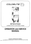
1
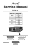
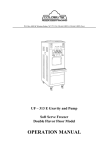
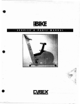
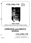
7 r
LB- 10OB BATCH FREELCFQ
ION and SE
A
COLDELlTECORWRATTON OFAMERICA
P.O. 3 0 X 4063
NORTH STATIGN *\NINSTCN-SALEM, N.C. 271 15 PHONE: (919) 661 -9
FOREWORD
T h a n k you f o r s e l e c t i n g COLDELlTE t o m e e t today's f a s t growing
d e m a n d s . Your COLDELITE f r e e z e r has been m a n u f a c t u r e d a t o n e
o f t h e m o s t m o d e r n f r e e z e r m a n u f a c t u r i n g plants in t h e U.S.A.,
o u r Winston-Salem, North Carolina facility, utilizing t h e most
a d v a n c e d e q u i p m e n t and technology available in t h e industry.
W e a t COLDELITE, t a k e g r e a t pride and c a r e in i h e m a n u f a c t u r e
o f e a c h a n d e v e r y f r e e z e r , using only t h e f i n e s t c o m p o n e n t s
a v a i l a b l e , t o p r o v i d e you w i t h y e a r s of trouble-free operation.
O v e r t w e n t y - f i v e y e a r s of e x p e r i e n c e in t h e m a n u f a c t u r i n g o f
d i s p e n s i n g e q u i p m e n t h a v e guided us in t h e p r e p r a t i o n o f this
O p e r a t i o n and S e r v i c e Manual. PLEASE READ IT CAREFULLY.
Keep it f o r f u t u r e r e f e r e n c e and most of all, follow t h e instructions
f r o m t h e v e r y t i m e y o u r m a c h i n e is put i n t o service.
O n t h e following pages, you will find i m p o r t a n t i n f o r m a t i o n and proc e d u r e s which d e s c r i b e t h e proper installation, sanitizing, operation,
a n d m a i n t e n a n c e o f y o u r COLDELITE machine. W e f e e l c e r t a i n t h a t
y o u r full c o m p l i a n c e with t h e s e instructions will a s s u r e you o f exc e l l e n t p e r f o r m a n c e , trouble-free o p e r a t i o n and a p r o f i t a b l e
b u s i n e s s f o r y e a r s t o come.
PACE A-1
INDEX
........................ - 1
......................... 1
............. .I
............ 2
............. 3
........ - 4
PART l
INSTALLATION
A) UNCRATING
8 ) P O S I T I O N I N G T i i E MACHINE
C1 E L E C T R I C A L REQUIREMENTS
0 ) E L E C T R I C A L CONNECTIONS
E l C O M P L E T I N G T H E INSTALLATION
PART I1
E X P L A I N A T I O N OF CONTROLS
A ) T H E SELECTOR SWITCH
8) T H E M E C H A N I C A L TIMER
C ) T H E DISPENSE H A N D L E
Dl T H E E L E C T R I C A L PANEL
E) O T H E R C O N T R O L S
.............. 4
.................L!
...............6
................
...............
6
6
.................... 8
........... - 8
P A R T Ill
I N I T I A L C L E A N I N G PROCEDURE
P A R T IV
A S S E M B L l N G THE F R E E Z E 2
A ) ASSEMBLLNC T H E 8EATER
0 ) ASSEMBLING T H E DISPENSE H E A D
PART V
SANITIZING THE FREEZE2
P A R T VI
S T A R T I N G T H E FREEZER
P A R T V11
O P E R A T I N G THE FREEZER
...............
70
.............. 71
........ 11
................ -12
..................13
................ 14
................ 15
...................... 1 5
...................... 15
....................... 16
P A R T VIII T E C H N I C A L INFORMATION
A) R E F R I G E R A T I O N
8) B E A T E R IVOTOR
C ) D R I V E SYSTEM
PART IX
......................... 16
............. 18
............... 20
................... 24
IVAINTENANCE
A) T i Z O U B L E SHOOTING GUIDE
81 P A R T S I N D E N T I F I C X T I O N
C ] W l i l l N G SCHEMATIC
MODEL LB-100 B
IMPORTANT
F a i l u r e t o closely follow set-up, operational and maintenance procedures
m a y r e s u l t in d a m a g e t o t h e unit and/or void your warranty. Coldelite
C o r p o r a t i o n will not b e responsible for any machine not properly maintained.
In t h e e v e n t this unit should malfunction, please c o n t a c t your C oldelite
D i s t r i b u t o r o r authorized service agency.
PART 1
INSTALLATlON
B e f o r e s t a r t i n g this procedure, make certain the shipping c a s e does not
show a n y evidence of having been dropped, tampered with o r abused in
s u c h a way a s t o indicate t h a t its contents may have been damaged in
transit.
IMPORTANT: Should t h e outside of t h e shipping case give any indication
o f possible hidden damage, s t a t e this on the bill of lading b e f o r e signing.
C o n t a c t t h e c a r r i e r immediately and request an inspection of t h e damage.
If t h i s procedure is not adhered to, you will forfeit your right t o file a
d a m a g e claim and be responsible for subsequent repair costs.
A1 U N C R A T I N C
P r o c e e d as follows:
1. R e m o v e t h e machine from its carton and remove all p r o t e c t i v e crating
material.
2. R e m o v e t h e single screw a t t h e bottom of each side panel. Remove
t h e s i d e panels by pulling in a downward and outward direction, allowing
t h e p a n e l t o slide free, The protective plastic coating which is laminated
t o t h e panels c a n now b e removed by simply peeling off.
B l POSlTlONING THE MACHINE
1. T h e m a c h i n e is now ready t o be positioned onto your counter. The counter
m u s t b e c a p a b l e of supporting 225 Ibs., and should be vibration free. Reinf o r c e it if necessary. Remember, when choosing a location, your unit
is a i r cooled, proper air flow will need t o be maintained. Allow a t least
six ( 6 ) inches on e i t h e r side and a minimum of twelve (1 21 inches between
t h e r e a r of t h e machine and any obstruction. (Ref. Fig. 1)
PACE
1
Front V i e w LB-1 OOB
Side V i e w La-1 008
FIGURE 7
C I e a r a n c e s Required For
Proper Air C o d i n g
NOTE: If t h e s e c l e a r a n c e s a r e not maintained, t h e production c a p a c i t y
will b e r e d u c e d , cycling will i n c r e a s e and t h e potential e x i s t s t h a t t h e
m t c h i n e will s t o p immediately.
2- The m a c h i n e should b e within f o u r f e e t o f the power supply outlet.
3, P o s i t i o n t h e ,machine f o r e a s y accessibility when cleaning, servicing
and p e r f o r m i n g r o u t i n e maintenance.
4- ? o s i ~ i o nt h e m a c h i n e a w a y f r o m d i r e c t sunlight. For =very Z O F a b o v e
6 8 O F , t h e machine's p e r f o r m a n c e w i l l d e c r e a s e b y approximatetv 1%.
5- Once t h e m a c h i n e is s e t in position, it should be leve!ed a s a c c u r a t e I y
a s possible.
C l E L E C T R I C A L REQUIREMENTS
All w i r i n g installed t o o p e r a t e chis f r e e z e r m u s be in a c c o r d a n c e with
t h e N a t i o n a l Eiectrical C o d e a n d l o r local elec;rical codes, rules and
r e g u l a t i o n s . T h e m a c h i n e must be properly grounded. It is r e c o m m e n d e d
t h e p o w e r supply be installed by a licensed electrician.
V O L T A G E La-1 008:
1 1 5 Voits
R U N N I N G AMPERACE FLA:
23-0
FUSE SIZE: 30 A M P Max.
W I R E SIZE: ( 5 0 Ft. Max.) = I 0
P O W E R S U P P L Y must b e a d e q u a t e t o meet requirement s a t all t i m es.
V o l t a g e f i u c ~ u a t i o n s ,nwit'n t h e machine in operation, should not e x c c e d
I 1036 o f t h e normal o r r a t e d voltacje.
PACE 2
T'ne mode! LB-1008 r e q u i r e s a 1 1 5 Volt o'O Hertz dedicated circuit ( no
o t h e r e l e c z r i c a i appliances o n t h e circuit)- X s e p a r a t e circuit b r e a k e r
rated a t 30 A M P S is r e q u i r e d
A D E Q U A T E WIRING must be provided with respect to wire size o r gauge.
This i n c l u d e s t h e direc? power line to the machine eiectrical and c o n n e c t i o n
ba x,
C o l d e l i t e b a t c h Freezers a r e equipped with protection f o r the b e a t e r rnot.or.
S h o u l d the l i ~ veo l t a g e crop, o r in t h e unlikely e v e n t a short c i r c u i t o c c u r s ,
t h e o v e r l o a d p r o t e c t o r wiil automatically discortneci t h e c o n t z c t o r . T h i s
w i i l s t o o t h e m a c h i n e i m m e d i a t e l y so that no p e r m a n e n t damage w i l l
b e c a u s e d t o t h t motor.
T o r e s t a r t t h e f r e e z e r , depress t h e reset button which is accessible titrouch
a n o p 2 n i n g a t t h e lower right c o r n e r of the r i ~ n sic?
t
panel. T h s p r o t e c t o r
m u s t cool f o r s e v e r a l minutes b e f o r e t h e r e s e t will o p e r a t e (Ref. Fig. 2 ) .
T h e c o m p r e s s o r is internally protec;ed. If ?he Klixon o r o t e c o r trips
d u e t o a n o v e r l o a d condition, t h e compressor w i l l stoo and a u i o n a t i c a 1 i y
r e s t a r ? o n c e :he p r o t e c t o r has cooied For several minutes.
01 ELECTXlCXL C O N N E C T I O N S (REF. FIG. 5 ) .
t i a v i n q r e m o v e d ;he r i c h t side pane!, ihe rntchine's t!ec;ricai conponen:!
w i r i n g c a n n e c : ~ nbox c z n b e locaitcf 2: i h e lower rich: corner. 2 e r n o v e
t h e e1ec;riczl c o n n e c t i o n box cover.
-.I ne )owe?
! i n e is f i r i t 7 a s s e ~t h r o u ~ h:he a c = s s hole I o c z ~ e dt t the b o t t o m
r i g h t e a r o f t h e machine:The iine is :hen ,asssa"iopwzrd thrcuc$ thc Z C C Z s i
-.
h o l e in t h e b o t t o m 62ck dirc~;iy i n l o t h e 1-!ec;riczl c3nmc;ion box. I n e
p o w e r i i n s r;.,ay now b e cannec:ed ia i ? r n i n a i s L i and i2. U ~ aZo o r o o r i z t e
?lec-trictl vvirinq 'narcware 2nd c o n n e c a r s a s governed b y e1ec:rictl cocks.
In all i n s t a l l a t i o n s , t h e machine MUST be properly grounded. Adequate
g r o u n d c o n t i n u i t y is assured by rum-ing and s e c u r e l y fastening a ground
line ( c o n d u c t o r ) t o :he ground lug [ o c a t e d in the e l e c t r i c a l connection box.
FIGURE
El COMPLETING T H E INSTALLATION
S a n i t a r y regulations m a y require that the counter model machine b e s e a l e d
t o t h e c o u n t e r top. T o seal, proceed as follows:
1.
C l e a n t h e c o u n t e r t o p thoroughly t o remove any dirt, dust, e t c .
2.
C l e a n t h e lower r i m , o r bottom flange of the machine base
( R e f . Fig. 3).
3.
Apply a bead [approx. 114" wide) of General Electric R T V 1 0 2 silicone s e a l n a t (or equivalent) t o t h e bottom s u r f a c e o f t h e
base.
4.
P l a c e t h e m a c h i n e on t h e counter in the location chosen.
5-
R e m o v e any e x c e s s sealant by slo'rvly running a f l a t edged
t o o l (spackling t o o l ) around t h e flange o f the base f r a m e .
This will c r e a t e a s e a m l e s s joint between the f r a m e and t h e
c o u n t e r t o p (Ref. Fig. 3).
6.
Allow s e a l a n t t o d r y thoroughly (refer t o sealant manufacturer's
d i r e c t i o n s ) b e f o r e operating t h e machine.
SILICONE
SEALANT
FIGURE 3
P A R T I1
EXPLANATION O F CONTROLS
All o p e r a t o r c o n t r o l s a r e conveniently located at the f r o n t of t h e machine.
(Ref. Fig. 4).
A) THE SELECTOR SWITCH
T h e s e l e c t o r s w i t c h is a four position, four function switch. The positions
o f t h e s w i t c h (Ref. Fig. 4) along with respective functions a r e a s follows:
1.
OFF
- The
m a c h i n e does not operate in t h i s position.
PACE 4
DISPENSE H E A D
I
RETAINING KN(
2- PRODUCTION - This position is used t o freeze t h e mix ingredients t o
a finished product. Both compressor and beater a r e in operation,
3,
EXTRACTION - This position is used for dispensing of frozen, finished
product. The b e a t e r is in operation and t h e compressor is inactivated.
4, CLEAN - This position is used f o r cleaning and sanitizing procedures.
O n l y t h e b e a t e r motor is a c t i v a t e d in t h i s mode. All refrigeration
c i r c u i t s a r e de-energized.
8) M E C H A N I C A L TIMER (Ref, Fig- 41
T h e mechanical t i m e r is a d e v i c e f o r setting t h e minutes required t o
p r o d u c e a b a t c h of finished product. At the end of t h e f r e e z e c y c l e
t h e t i m e r will signal and audible reminding t h e operator t h e production
c y c l e , finished product, is completed. T h e t i m e r is a reminder only and
d o e s not t u r n off t h e machine, The t i m e r w i l l be discussed in detail
in P a r t VI, Starting T h e Machine,
C) DISPENSE HANDLE (Ref. Fig. 4 )
Moving t h e dispense handle in an upward direction raises t h e g a t e cover
f o r dispensing finished product. A downward motion closes t h e gate.
I
FIGURE 5
PAGE 6
T h e E i e c t r i c a l C o n t r o l Panel, l o c a t e d behind t h e right hand side panel
a n d in t h e lower r i g h t corner, contains t h e components f o r t h e m a c h i n e
c o n t r o i l i n g c i r c u i t . This panel is to be a c c e s s e d only by trained, e x p e r .ienced technicians.
WARNING!
D I S C O N N E C T F R E E Z E R FROM THE SOURCE OF ELECTRICAL SUPPLY
B E F O R E ATTEMPINC TO SERVICE.
T h e following is a n explanation o f t h e control panel components:
COMPRESSOR CONTACTOR - A c t i v a t e s t h e refrigeration
c o m p r e s s o r . When t h e m a c h i n e is o p e r a t e d in t h e
PRODUCTION mode, t h e c o m p r e s s o r c o n t a c t o r will
b e e n e r g i z e d b y t h e e l e c t r o n i c Hard-0-Matic control
(H.O.M.).
BEATER MOTOR CONTACTOR - A c t i v a t e s t h e b e a t e r
d r i v e motor. T h e b e a t e r m o t o r c o n t a c t o r is energized by
t h e s e l e c t o r s w i t c h when e i t h e r in t h e ?RODUCTION,
EXTRACTION o r CLEAN MODES.
OVERLOAD PROTECTOR - Senses t h e c u r r e n t ( a m p e r a g e )
supplied t o t h e b e a t e r motor. in t h e event of a c u r r e n t
o v e r l o a d , t h e p r o t e c t o r will t r i p and stop t h e e n t i r e machine.
T h e t r i p AMPS h a v e b e e n pre-set a t the f a c t o r y and a r e
i n d i c a t e d o n t h e control panel cover, This d e v i c e also
c o n t a i n s t h e o v e r l o a d r e s e t mechanism. If r e s e t is
r e q u i r e d , position t h e s e l e c t o r s w i t c h t o t h e O F F position
b e f o r e pushing t h e r e s e t button. R e t u r n s e l e c t o r switch
t o t h e d e s i r e d mode.
ELECTRONIC HARD-0-MATIC (H.O.bl.) - Automatically
s e n s e s and c o n t r o l s product consistency when t h e f r e e z e r is
o p e r a r i n g in t h e PRODUCTION mode. Depending on signals
r e c e i v e d f r o m t h e b e a t e r drive m o t o r , t h e H.O.M. a c t i v a t e s
o r s t o p s t h e r e f r i g e r a t i o n s y s t e m t o maintain pre-set product
consistency.
C U R R E N T TRANSFORMER - Monitors b e a t e r m o t o r c u r r e n t
c h a r a c t e r i s t i c s a n d provides signal t o H.O.M.
T R A N S F O R M E R (MAIN) - Steps d o w n t h e primary 115 line
v o l t a g e t o 24 v o l t secondary supply for t h e control circuit.
TERMINAL BLOCKS ( 1 15 Volt) - Inter-connection point f o r
high v o l t a g e components, I.E. compressor, main t r a n s f o r m e r ,
b e a t e r m o t o r , a n d condenser fan motor. Also, used to c o n n e c t
p o w e r supply wires.
PACE 7
8 8 9 TERMINAL BLOCKS (24 Volt) - Serves as t h e interconnection point
f o r all 2 4 volt controlling circuit components.
El OTHER CONTROLS
1.
HIGH PRESSURE CUT-OUT CONTROL - Located on t h e right side
of t h e f r e e z e r ' s upper left corner, and is installed into t h e compressor
discharge line (high pressure side). In the event of a high pressure
condition, it will shut down the compressor. Reset is a u t o m a t i c when
t h e high pressure subsides. A common cause for cut-out is r e s t r i c t e d
a i r flow through t h e condenser coii.
2.
SAFETY SWlTC H DISPENSE HEAD - ' The switch is located behind
t h e f r o n t panel and is a normally open switching device t h a t is mechanically a c t i v a t e d t o t h e closed position when t h e dispense head
is securely closed and latched with t h e retaining knob. Should an
a t t e m p t b e m a d e t o open t h e dispense head during f r e e z e r operation,
t h e switch a u t o m a t i c a l l y opens de-energizing t h e machine.
PART 111
INITIAL CLEANING PROCEDURE
T h e new machine m u s t b e completely disassembled, washed, and sanitized
p r i o r t o starting. P r o c e e d as follows:
1.
Remove t h e i t e m s packaged with t h e freezer, (spare p a r t s or s t a r t up kit, sample sanitizer, and sanitary lubricant).
T H E SPARE PARTS OR START UP KIT will include; a c o m p l e t e s e t of r e p l a c e m e n t
o-rings and rubber seals, o-ring e x t r a c t o r , cleaning brush, a -tube of s a n i t a r y
lubricant, four sample packages of sanitizer, a spatula, and t h e Cperation and
S e r v i c e Manual.
HELPFUL SUGGESTION: Before proceeding with t h e disassembly of t h e f r e e z e r ,
it is r e c o m m e n d e d t h a t a plastic dish pan be used in which t o place t h e parts.
This will minimize t h e possibility of misplacing or damaging t h e various compone n t parts.
2; Proceed with t h e disassembly by removing t h e dispense head
(Ref. Fig. 61.
PACE 8
FILL CHUTE COVER
RETAINING R O D
DISPENSE HEAD
GATE COVER
TENSION S P R I N G
DISPENSE C H U T E
I
FIG, 6
DISPENSE HANDLE
DISPENSE HEAD
... . .
G r a s p a n d pull t h e retaining knob outward. Rotate t h e knob clockwise o n e . q u a r t ~ r
t u r n t o unlatch t h e dispense head.
Swing t h e dispense head open and lift upward removing it from t h e hinge pin.
3.
F u r t h e r disassemble t h e dispense head by removing t h e fill cover
retaining rod and t h e plastic fill cover.
To r e m o v e t h e dispense handle and g a t e cover, carefully unscrew t h e dispense
h a n d l e pivot knob a t t h e left and slowly pull the handle forward releasing t h e
h a n d l e , tension spring and g a t e cover.
4.
Remove t h e b e a t e r f r o m t h e f r e e z e r cylinder with a s t r a i g h t
and forward pull. Slide t h e rubber beater shaft (lip) s e a l o f f
of t h e b e a t e r shaft.
5.
Using t h e O-RING E X T R A C T O R , remove t h e large o-ring
f r o m t h e b a c k of t h e dispense head, and t h e g a t e c o v e r o-ring.
6.
The machine is now completely disassembled. The p a r t s will
be washed, rinsed and sanitized. (Ref. Fig. 71.
PACE 9
7.
Wash all p a r t s in luke-warm water (80'-85OF) using a mild
d e t e r g e n t and t h e c l e a n i n g brush provided in t h e STARTUP KIT.
DO N O T USE HOT WATER FOR PROCESSING A N Y O F THE PLASTIC P A R T S
A S D A M A G E TO THE PARTS C A N RESULT.
8,
R i n s e t h e p a r t s in luke-warm w a t e r 180°-8S°F).
9,
P l a c e t h e p a r i s in luke-warm w a t e r , containing s a n i t i z e r , f o r 2
t o 5 minutes. Use t h e s a m p l e sanitizer provided in t h e STXRTU P KIT following t h e m a n u f a c t u r e r ' s directions.
10. A r r a n g e t h e p a r t s on a clean, sanitized counter a r e a a n d allow
t o a i r d r y o r r e a s s e m b l e wet if desired. DO NOT TOWEL D R Y
OR RINSE THE SANITIZED PARTS.
1 1 . T h e cylinder walls m u s r also be washed and rinsed using lukew a r m w a t e r (80'-8S°F), mild d e t e r g e n t , and followed by
wiping with s a n i t i z e d w a t e r . Allow cylinder t o air d r y o r
r e a s s e m b l e wet.
P A R T IV
ASSEMBLING THE FREEZER
O n c e t h e c y l i n d e r and p a r t s h a v e been washed, rinsed and s a n i t i z e d , t h e
f r e e z e r is r e a d y t o b e re-assembled. Prior to beginning t h e re-assembly
p r o c e d u r e , s a n i t i z e your hands by submerging in sanitizing solution. Rea s s e m b l e a s follows:
P A C E 10
A) ASSEMBLING
.
THE BEATER
1.
Lubricate and install t h e BEATER LIP SEAL. Using
t h e s a m p l e s a n i t a r y lubricant included in t h e STARTUP KIT, lightly c o a t t h e front and back surfaces of t h e
seal and slide t h e seal onto the S e a t e r shaft.
2.
Insert t h e BEATER into t h e freezing cylinder. Hold t h e
b e a t e r horizontal and slide it into t h e cylinder until it will
go n o further. Be sure t h e BEATER LIP SEAL is in place.
3.
R o t a t e t h e B E A T E R until you feel t h e drive shaft engage
and push t h e b e a t e r f u r t h e r toward t h e r e a r t o properly
seat.
B l ASSEMBLING T H E DISPENSE HEAD (Ref, Fig. 6).
1.
Begin by gathering all of t h e parts required t o assemble
t h e DISPENSE H E A D . These parts include: one (11 dispense
head o-ring, dispense head, fill cover, fill cover retaining rod,
gate. cover, g a t e cover O-ring, tension spring, dispem2 handle
and retaining kcob.
2.
lnstall t h e o-ring into t h e g a t e cover a-ring groove. Lightly
l u b r i c a t e t h e o-ring with sanitary lubricant for f r e e movem e n t of t h e g a t e cover during dispensing.
3.
Position t h e tension spring between the handle and g a t e cover
r e c e s s and r e m o u n t t h e handle onto the pivot stud. lnstall
t h e white plastic retaining knob.
4.
Re-attach t h e fill cover t o t h e fill chute by inserting its
retaining rod.
5.
Install t h e dispense head o-ring into t h e o-ring groove
l o c a t e d on t h e back side of t h e head, Lubricate t h e a-ring
with a light coating of sanitary lubricant.
6.
A t t a c h t h e DISPENSE HEAD t o t h e f r e e z e r by guiding t h e
head pivot o n t o t h e hinge pin.
7. Close t h e dispense head and latch into place with t h e
retaining knob.
The m a c h i n e is now completely assembled and ready t o be sanitized.
PAGE 11
PART V
SANITIZING THE FREEZER
P r i o r t o starting t h e f r e e z e r with the product t h a t will b e served, t h e f r e e z e r
m u s t b e sanitized,
S a n i t i z i n g t h e f r e e z e r is most important as the procedure r e t a r d s t h e growth
o f b a c t e r i a and insures a c c e p t a b l e product test results when examined by local
H e a l t h and/or Agriculture Departments.
The frequency of cleaning and sanitizing cycfes must comply with local Health
Regulations. If uncertain about t h e regulations in your a r e a , c o n t a c t t h e local
Board o f Health or D e p a r t m e n t of Agriculture.
T o begin t h e sanitizing process, you will need a ctean pail, wire wisk, and a
s o f t p l a s t i c bristle brush.
7,
Mix 2 9z. of sanitizer, STERA SHEEN 'GREEN L A B E L
0 R EQUIVALENT, (sample packs included in t h e STARTUP KIT1 into a pail containing one gallon of warm water.
Dissolve s a n i t i z e r by stirring w i t h a wire wisk, This
formula w i l l m a k e a 200 P.P.M. (parts per million1
concentration of chlorine sanitizing solution.
IMPORTANT: Do not e x c e e d t h e formula r2com'mended by t h e sanitizer
m a n u f a c t u r e r as it will not add t o its effectiveness.
2.
Lift t h e fill c h u t e c o v e r and pour t h e sanitizing solurion
into t h e cylinder until t h e solution rises in t h e fill chute.
3.
Turn t h e s e l e c t o r switch to the C L E A N position f o r 30
seconds (Ref. Fig. 4, PC, 5). The beater will run
allowing t h e sanitizing solution to come in c o n t a c t with
all internal product c o n t a c t areas. During t h e 30 second
CLEAN period, t h e remainder of t h e one gallon of sanitizing solution should b e added filling the fill chute*
4.
Turn t h e s e l e c t o r t o t h e O F F position.
5.
Using a s a n i t i z e d s o f t tsrisile brush, brush t h e dispense
chute, t h e underside of t h e f i l l cnute cover, and t h e sides
of t h e fill c h u t e t h a t will come in c o n t a c t With product.
Close t h e fill cover. Allow the sanitizing solution t o
remain in c o n t a c t with t h e product areas for t h r e e ( 3 )
t o five ( 5 ) minutes.
6.
P l a c e a c l e a n pail u n d e r t h e dispense c h u t e a n d
slowly r a i s e t h e d i s p e n s e handle and g a t e c a v e r
t o d r a i n t h e s a n i t i z i n g solution from the cylinder.
7 , Allow t h e s a n i t i z e r t o drain completely. Close
t h e dispense handle,
HELPFUL SUGGESTION: When :he sanitizer has stopped flowing f r o m
t h e d i s p e n s e head, l e a v e t h e d i s p e n s e handle in t h e OPEN position and
t u r n t h e s e l e c t o r s w i t c h t o t h e CLEAN position f o r two t o t h r e e s s c o n d s
t o a s s i s t in r e m o v a l o f t h e l a s t b i t o f sanitizer.
DO NOT RINSE THE I M A C H I N E W I T H FRESH WATER AFTER T H E SANITIZING
. P R O C E S S HAS BEEN COlMPLETED AS THIS ACTION WOULD COIMPLETELY
N E G A T E THE ENTIRE PROCESS.
C A U T I O N : It is r e c o m m e n d e d :hat t h e S e a t e r b e t u r n e d a s little as possible
c u r i n g t h e washing and sanitizing processes a s e x c e s s i v e r o t a t i o n
c a n result in p r e m a t u r e wear of b e a t e r b l a d e s u r f a c e s ;
P A R T V1
STARTING T H E FREEZER
Only a f t e r t h e m a c h i n e has been thoroughly cleaned and s a n i t i z e d is t h e f r e e z e r
r e a d y f o r production of t h e initial batch,
You h a v e t h e f i n e s t , f a s t e s t a n d most dependable f r e z l c r m a n u f a c ~ u r e d ~
C o n g r a f u l a t i o n s ! You a r e now r e a d y 70 make hard ice c r e a m , s n e r b e i s , ices,
g e l a t o a n d more,
A succlcssfull r e t a i l business d e p e n d s entirely on t h e q u a l i t y of t h e product it
p r o d u c e s - T h e r e f o r e you a r e u r g e d t o choose wisely only q u a i i t y inqredients
f o r t h e f o r m u l a t i o n of your f r o z c n products. Please r e m e m b e r , inexpensive and
i n f e r i o r i n g r e d i e n t s will result in a similar inferior product a n d a disatisfied
customer.
Please o b s e r v e t h e following recommendations:
1.
itlake your m i x e s f r o m . high quality natural p r o d u c r s
o r o b t a i n f r o m a r e l i a b l e and trustworthy supplier.
2- Do n o t s e r v e t h e p r o d u c t t o the customer unless its
quali:y and a p p e a r a n c t w e entirzly saris7ac;ory.
P A C E 73
3.
Be s u r e t h e m a c h i n e is k e p t clean a t a l l times.
4.
In t h e e v e n t t h e f r e e z e r requires service, always c o n t a c t
a n a u t h o r i z e d COLDELLTE Technician.
B a t c h s i z e s will v a r y depending on t h e mix ingredients, desired overrun, etc,,
E x p e r i e n c e will be t h e t e a c h e r f o r judging t h e desired size o f e a c h batch. F o r
e x a m p l e , when making ices, a larger quantity of mix may be poured into t h e
c y l i n d e r a s t h e final finished b a t c h w i l l have less expansion d u e t o m i n i m u m
overrun.
T h e initial q u a n t i t y o f mix t o b e . p o u r e d into t h e cylinder is a minimum o f 1.7
q u a r t s (54 oz.1 and 2.2 q u a r t s (70 oz.) maximum, As a guide, when c h a r g i n g
t h e c y l i n d e r with mix, t h e horizontal mix level mark on the dispense h e a d will
i n d i c a t e a fill o f 1.9 q u a r t s ( 6 0 oz.).
P r e p a r e 1.7 t o 2.2 q u a r t s o f liquid mix, approximately 38' t o 42OF, in a c l e a n ,
-sanitized measuring container.
P A R T VII
OPERATING
THE F R E E Z E R
P o u r t h e mix into t h e fill c h u t e and close t h e c h u t e cover.
S e t t h e t i m e r t o T O m i n u t e s and t h e selector switch t o
PRODUCTION. (Ref. Fig. 4, Pg. 51.
Allow t h e m a c h i n e t o f r e e z e t h e product t o t h e desired
c o n s i s t a n c y - T h e t i m e r m a y produce an audible prior t o or.
a f t e r t h e completion of t h e f r e e z e cycle. The 10 m i n u t e
t i m e r s c t t i n g is a n average. Exact timing must be arrived
a t b a s e d on t h e mix used, desired overrun and firmness,
a n d t h e consisiancy control setting t o b e discussed in
P A R T V I I I TECHNICAL INFORMATION.
O n t h e initial b a t c h when t h e timer sounds a t 10 minutes,
t u r n t h e s e l e c t o r s w i t c h t o EXTRACTION. lift t h e dispense
h a n d l e and d r a w t h e finished batch f r o m t h e cylinder into
a s a n i t i z e d , cold container. After dispensing is c o m p l e t e
r e t u r n t h e s e l e c t o r s w i t c h t o OFF.
N o t e t h a t t h e s e c o n d b a t c h will b e m a d e in a lesser time. Again, e x a c t t i m i n g
m u s t b e c o n c l u d e d b a s e d on t h e desired finished product c h a r a c t e r i s t i c s .
When working with d i f f e r e n t flavors, plan t h e sequence of b a t c h e s b e f o r e hand,
E x a m p l e , a l w a y s s t a r t with vanilla, possibfy c h e r r y vanilla, vanilla chip, f o [ l o w e d
by c o f f e e , w a l n u t o r o t h e r light colored flavors. Naturally, c h o c o l a t e would be
t h e f i n a l f l a v o r dispensed.
P A C E 74
Always r e m e m b e r t o use quality ingredients. Producing quality ice creams,
ices o r s h e r b e t s will g u a r a n t e e a superior product and a happy customer.
P A R T VIIl
T E C H N I C A L INFORMATION
A) R E F R I G E R A T I O N
Compressor: H e r m e t i c , .75 H.P., R-502 Refrigerant
Voltage: 1 1 5 Volt, Single Phase, 60 Hertz
FLA: A m p e r g a e = 2 3
Suction Pressure: 19 PSI
Discharge (Head) Pressure: 2 2 5 PSI
Cooling System: Air
R e f r i g e r a n t Charge: 1.8 LBS
B) B E A T E R MOTOR
Voltage: 715 Volt, Single Phase, 60 Hertz, 3/4 H.P.
H.0.M: Cut-out A m p e r a g e 6.3 t o 6.7
Overload C ut-out Amperage 7.6
1 ) Adjusting B a t c h T e m p e r a t u r e
T h e LB-1008 uses a Hard-0-Matic system which is referred t o as H.O.M..
This e l e c t r o n i c d e v i c e controls the refrigeration system for t h e freezing
cylinder by 'sensing' t h e consistency or hardness of t h e product inside t h e
f r e e z i n g cylinder. No t h e r m o s t a t s a r e used with this system.
T h e firmness o f t h e b a t c h product will depend on t h e s e t t i n g o f t h e H.O.M.
e l e c t r o n i c control.
T h e c o m p r e s s o r must c u t off when t h e current, absorbed by t h e b e a t e r motor,
r e a c h e s t h e a m p e r a g e indicated on t h e label i n t h e electrical control box
(H.O.M. Cut-out AMPS). By using an a m m e t e r and clamping around o n e leg
o f t h e power line feeding t h e b e a t e r motor, it is possible t o r e a d t h e a m p e r a g e
drawn by t h e motor. Factory s e t cut-out is 6.3 t o 6.7 AMPS.
2 ) E l e c t r o n i c Hard-0-Matic Control Adjustment
T o r e d u c e product consistency, turn t h e TRfMMER adjustment (see Fig. 8).
c o u n t e r clockwise.
T o i n c r e a s e product consistency, turn t h e TRIMMER adjustment screw
clockwise.
The e l e c t r o n i c H.O.M. (see Fig. 8) has the possibility of working in t h r e e
d i f f e r e n t r a n g e s of amperage- Be sure that t h e range s e l e c t e d is in
a c c o r d a n c e with t h e b e a t e r motor amperage range, If modification is
required, r e m o v e t h e bridge and reposition o n t h e appropriate range(See Figure 8).
PAGE 15
u
3-2-6-2 AMP
BRIDGE
uu
7 -8-3-7A M P
4.5-9-0
AMP
To obtain a different H.O.M. range, from t h a t
the factory setting, t h e bridge must be moved
the pins as shown in A , B , C , and D for t h e requi
amperage. The f a c t o r y bridge s e t t i n g 'Dl will n
likely be suitable f o r all tnixes and will rarely r
quire repositioning.
SEE D E T A I L A T R I G H T
FIGURE 8
Cl D R I V E S Y S T E M
T h e r o t a t i o n of t h e b e a t e r is counter clockwise 2nd is motivated by a belt
d r i v e system.
P A R T IX
MAINTENANCE
Your C O L D E L I T E m a c h i n e has been designed, engineered and m a n u f a c t u r e d to
a c h i e v e high p e r f o r m a n c e and long durability.
T h e l i f e e x p e c t a n c y of a machine, any machine, does not depend only on t h e
q u a l i t y o f its components and design, but also on the beneficial e f f e c t s of
basic procedures.
It is i m p o r t a n t t o you, t h e r e f o r e , to become familiar with a few of t h e s e
b a s i c procedures:
P A C E 16
R e m o v e '0' rings only with t h e '0' ring e x t r a c t o r supplied with
t h e machine.
C l e a n t h e machine according t o t h e instructions.
L u b r i c a t e all '0' rings and seals, as instructed.
T h e wearing or t h e improper cleaning of t h e b e a t e r shaft seal, will
r e s u l t in leakage from t h e rear. Check the drip t r a y frequently and
r e p l a c e t h e seal when necessary.
R e p l a c e any '0' ring that has a nick in it. If not replaced, it will leak
a n d i n t e r f e r e with t h e proper performance of the machine.
When all t h e spare parts supplied with t h e machine a r e used, re-order
i m m e d i a t e l y . Do not wait until t h e part is required again.
N E V E R use the AUTO position for washing, sanitizing and initially
filling t h e freezing cylinder.
I M P O R T A N T - During t h e washing and sanitizing period, run t h e m a c h i n e
o n l y f o r t i m e strictly necessary for this operation. Prolonged use of t h e
b e a t e r in t h e Cleaning position may cause severe damage t o t h e machine.
Always wash metal, plastic o r rubber parts in lukewarm water. NEVER,
N E V E R USE H O T WATEF?!
IMP0 RTANT
As t h e model LB-1000 is an air cooled machine, its efficiency depends on t h e
a i r c o o l e d condenser. T h e fins of t h e condenser must be cleaned e v e r y t w o
o r t h r e e months t o assure efficiency.
Extreme c a r e must be taken when removing side, r e a r or control box panels.
A l w a y s t u r n t h e Selector Switch t o t h e O F F position. Also, turn o f f t h e
D i s c o n n e c t Switch on t h e electrical supply line before exposing any
e l e c t r i c a l connections andlor moving parts, such as belts, pulleys, fan
blades and beater.
P A C E 17
T R O U B L E SHOOTING GUIDE
PROBLEM
POSSIBLE CAUSE
SUGGESTED R E M E D Y
1 ) Machine will not s t a r t
a ) No power t o t h e machine
a ) Check c i r c u i t break
s e l e c t o r s w i t c h posi
and power supply wi
b) Wait 5 m i n u t e s and
push r e s e t b u t t o n
c ) C o n t a c t s e r v i c e age
b) Off on overload
c ) Malfunctioning selector
switch
d ) Dispense head
safety switch not
energized
e) Beater motor
and compressor
contactor not
energized
2)
Product t o o s o f t
a ) H.O.M. control out of
calibration o r malfunctioning
b) Machine low on refrigerant
c ) Insufficient freezing t i m e
3)
P r o d u c t t o o hard
4 ) M a c h i n e will not f r e e z e
d) Check i f dispense he
is properly closed ar
if pin is a c t i v a t i n g
the safety switch
located behind t h e
front panel
e ) Check if 2 4 volt
t r a n s f o r m e r is operating properly
a) Contact authorized
service a g e n c y
b) C o n t a c t a u t h o r i z e d
service a g e n c y
C ) increase f r e e z i n g tir
a ) Freezing t i m e too long
a ) Check f o r proper
freeze t i m e and the
H.O.M. s e t t i n g
a ) Restricted air flow
a ) Remove obstruction
or r e s t r i c t i o n
b) C o n t a c t a u t h o r i z e d
service agency
c ) C o n t a c t authorized
service agency
d ) C o n t a c t authorized
service agency
e l C o n t a c t authorized
service agency
fl C o n t a c t authorized
service agency
b) Compressor not working
c) System refrigerant
low
d ) Malfunctioning
H.O.M.
e) Malfunctioning
cont actor
f l Insufficient power supply
PACE 18
5)
Compressor will
not s t a r t
a ) Low line voltage
b) Open starting
capacitor. Relay contacts
not closing
c ) Off on high pressure
a ) Check power supply
voltage. Determine
voltage drop
b) Replace s t a r t c a p a c
Replace d e f e c t i v e rc
cl Clean condenser.
Refrigerant over-ch;
6) Compressor o p e r a t e s
long o r continuously
a ) Shortage of refrigerant
b) Dirty condenser
c) Location t o o warm
a ) Repair leak and
recharge
b) Clean condenser
c) Change t o cooler
locat ion
7 ) Burnt rubber
odor
a ) Product in cylinder
frozen too hard
bl Drive belt slipping
a) Refer t o H.O.M.
adjustment
b) Tighten belt
81 Mix dripping f r o m
a) Damaged or worn O-ring
a ) Replace suspect
o-ring
a ) Damaged or worn beater
seal
a ) Replace beater seal
dispense head
9) Mix dripping from side
overflow drip t r a y
PAGE 19
LB-100B PARTS IDENTIFICATION
FIGURE A
7
CODE NO.
l6W25O
/
Retaining Knob
1657380'
/
Retaining Sprinq
1720070*
Seal -Selector Switch
1720110
Selector S w i t c h - Cornpiete
17201 72'
Knob -Selector Switch
1723070
'
DESCRIPTION
1
Mechanical Timer
1745050
Plastic Drip Tray
1745390
Console
1902151
Panel
- Left
1903142*
Panel
- Riqht Side
1904141f
Panel
- Rear
19071 30
Panel
- Top
Side
*Not Pictured
PACE 20
1
1
LB-1006 PARTS IDENTIFIC ATlON
1
1657020
FIGURE 8
Dispense Head - Plastic
1651341
Gate Cover - Round
1652340
I
I
Knob - Bail
1654080
Retaining Rod
1 1657020
1
1657200
I
I
1
1657350
I
- Cover
t
Stud - Ball Knob
I
!
---- --
Dispense Handle
I
Dispense Chute
Pivot Bracket
1 657270
1
t
1653290
165FT310
i
DESCRIPTION
CODE NO.
- Dispense
Tension Sprinq - Gate Cover
1750490
Fill Cover
341 01 30
0-Ring 228
1685160
0-Ring 443
35 16390
Screw
- Ball
Knob
PACE 21
I
Head
- -
I
LB-1008 PARTS IDENTIFlC ATlON
A-
1785170
DESCRIPTION
1411190
151 8090
1
1
1612120
Base - Transmission Housing
16 1 3091
/
Shaft
1616180
/
Seal
1640471
j
/
3202050
320321 0
Beater
Ball Bearing
Drive Belt
1914260
31 121'80
I
Motor Sheave
1708271
I785170
- Drive Transmission
Flywheel
1618201
1
B e a t w Seal
Snap Ring
I
1
i
Condenser Fan
Beater Motor
Condenser Fan Motor
P A C E 22
I
LB-1008 PARTS IDENTIFICATION
E L E C T R l C X L PARTS (REFERENCE FIG-3PC-61
I
ITEM NO.
1
2
1
/
3
7
5
I
7
8
/
9
I
1
1
/
1
1
1
i
1
1
CODE NO.
!
1729350
C o m p r e ~ s a rContactor
1724350
1
1729660
/
Overload Protector
17237b0
1
Electronic H.O.M.
Beater Motor Cantactor
i
3213500
1
Current Transformer
3213090
1
M a i n Transformer
TerminaI 31ock '115 V
(Individual Block)
Terminal Glock 24 V
(Individual 4 Conductor)
3219400
171
1711550
1
!
1
DESCRIPTION
Terminal Block 24 V
(Individuai 2 Conductor)
I
SPARE PARTS NOT PICTURED
I
DESC RIPTlON
C O D E NO.
I
1
SpatuIa
0-R inq E x t r a c t o r .
1I
1745380
'
1746010
1
1
i
1
j
7746020
'
Arm-Belt Tension
3250060
/
S a f e t y SwitcfrDisp. Head
3250410
Reset Button-Complete
3250420
Pulley-Belt Tension Arm
1
I
1
I
EXPANSION V A L V E
Orifice f o r 1727500
I
1
3306390
I
Orifice for 1727560
Air Condenser
1
!
1
1
1
1
DESCRIPTION
Screw-Console MTG.
II
C o v e r D r i o Tray Hole
I
Sprinq-Cover
Compressor S t a r t
capacitor
Beater Motor S t a r t
CaDacitor
Beater Motor Run
Capacitor
Compressor Rela"
Compressor -75 H P
I
I
Hiqh Pressure Cut-Out
I
35401 10
Shroud f o r 173 1200
PACE 23
1
Sanitary Lubricant
\
1
I - I - I
OFF
EXTRACTlON
P R O D U CT l O N
BEATER
TTA
1-
TTA
I-"+
RTA
1
TTA
RTA
RTA
T R 115 V A C
LB-1 00B
WIRING S C H E M A T I C
CR
H O--M
---
.--OOT.AR.YiSVI.TCti-.
-
. .- .-.. ... .
.-HA~D-~~~MA~.IC,ELEC~RON
L - BEATER-DRIVE MOTOR'
MC
MIP
-PR
MV
C;RMPRESSL)R
..
.. .
. -. .
.
.
.
.
...
.
.F.[3_S1.NT-~lR-SAET.Y-SWIT-CI-I..
..
H I G H PRESSURE CUT-OUT
-*--------.---------.----.... ---- - - .. .CONDENSER F A N M O T O R --- .. -
O V E R L O A D B __E ._._
A T..._
ER M
R T A . _________-_.
. .-O
--T O
.- ....R- TR
. ..-LfiNSFP-n_MErl.. . .... . .
CURRENT TRANSFORMER
CONTACTOR
.--------.---.
- BEATE-R.MTR
rnNTArTnR-TnMPRF<sOR