1
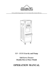
Soft Serve Freezer
OPERATION and SERVICE
MANUAL
COLDELITE CORPORATION OF AMERICA
543260
3760 INDUSTRIAL DR.
WINSTON-SALEM, N.C. 27105
TEL (919) 661-9893
FAX (949) 661-9895
Page
PART I
.
A)
L!ni i at l n y
l ' o s i t i o n i n q the M a c h i n e
C ) Machines w l t h Water Cooled
K a t e r V a lvc Adjustment
B)
Condensers
\<AHSING
D) M s c t ~ i n e swith Air Cooled Condensers
El
PART- I I
Electrical. Connections
E l e c t r i c a l Requirements
B e a t e r Kvtatlon
IYI:(?HTAN'I' - W A R S I N G INFORMATION
EXI-'L.ANA'I'IOX
--
CONTROLS
Of.'E L E C T R I C A L-----.-
Conrrol Panel
B ) Oth~>r
Controls
A)
PART I 1 1
PART I V
Asst2rnb 1 ing the
Freezer
8, 9, 9a
S A N I T 1 Z I I:(;
FREEZER
10, 10a
13
THE
.-.-
Routine, Periodic Cleaning Procedures
PART V
S T A R T 1 NG TtiE F R E E Z E R
PART VI
GENERAL INFORMATION
Gravity Feed-Valve and How to Operate
:low to Adjust the Gravity Feed Valve
12
12
TEChS1CF.-L DATA
14
A)
Rcfr-igcrztion - Compressor, Beater Motor
Adjustiny Product Temperature
H w to Ad just Hear Micro Switch
Cue.-Cut Arnperaqe
WAiiT4 1 KG
Hard-0-Matit Springs
Mix Tank Refrigeration
Energy Conservation Switch
a) How It Operates
b) Calibration of Temperature in
Cylinder
c ) Calibration of Temperature in
Hopper
14
14
15, 16
14
16
16
17
17
17
17
I N D E X
Page
2 ) B E A T E----R ACTIVATING SWITCH
a n d How I t Operates
flow to A d l u s t t h e F r o n t Micro Switch
C ) M A I N T E N A N CE
WARL I NG
TROUBL,E SHOOTING
-
Appendix
-
GUIDE
Figures 1
- 9
Wiring D l a y r a m s
Legend of Schematic Symbols
Parts
-
Description and code Numbers
18
F O_ _
R _
E --W
- O R D
. .
Thank you for stlectir~g COLDELITE to meet today's fast
freezer has been manugrowing demands. your COI,DELIT~
factured at t h e most modern freezer manufacturing plant
in the U.S.A., our I , o d ~ , New Jersey facility, utilizing
the most advanccd cqul:)mcnt and technology available in
the industry. W e , a t coldelite, take great pride and
care in the manufacture o f each and every freezer, using
only the finest co7,poncnts available, to provide you with
years o f trouble- f ree operation.
Over twenty-flve ycars o f cxpcrlence in the manufacturing
o f d i s ~ e n s r n gequik)ment h a l ~ cgulded us ln the preparation
of thls Operation and Service Manual. PLEASE READ IT
CAREFULLY. Keep it for future reference and most of all,
follow the rnstructlons from the very time your machine
is delivered.
On the following p3ges, you wlll find important inforrnation and procedures whlch describe the proper installation,
sanitizing, operation and maintenance of your COLDELITE
machine. b'e feel certaln that your full compliance with
these instructions will assure you o f excellent performance,
trouble-free operatior, and a profitable business for years
to come.
N O T I C E
Failure to closely follow set-up.and maintenance procedures
can void your warranty. Coldelite Corporation will not be
responsible for any machine not properly maintained.
In the event this unit should malfunction, please contact
your Coldelite distributor or an authorized service agency.
W A R N I N G
EXTRE5iE CARE MUST BE TAKEN WHEN REMOVING SIDE,
REAR OR CONTROL BQX PkKELS.
TURN THE SELECTOR SWITCH TO THE O F F
POSITION. ALSO TURN OFF THE DISCOKNECTSkITCH ON ELECTRICAL SUPPLY LINE BEFORE
EXPOSING ANY ELECTRICAL CONNECTIONS AND/OR
tiOVINS PARTS, SUCH AS BELTS, PULLEYS, FAN
BLADES AND BEATER.
AL\iAYS
Paqe 1
I
--
N S T A L L A T I O N
P A RT I
A
-
UNCRATING
-
B e f o r e s t a r t i n g t h i s p r o c e d u r e , make s u r e t h e c a r t o n
d o e s n o t show e v i d e n c e of h a v i n g b e e n d r o p p e d , t a m p e r e d w i t h
o r a b u s e d i n s u c h a way a s t o i n d i c a t e t h a t i t c o n t e n t s may
h a v e b e e n damaged i n t r a n s i t .
IMPORTANT - I n t h e e v e n t t h e o u t s i d e o f t h e C a r t o n s h o u l d
g r v e a n y indication o f p o s s i b l e h i d d e n d a m a g e , s t a t e t h i s
o n t h e b i l l of l a d i n g b e f o r e s i g n i n g . C o n t a c t t h e c a r r i e r
i m m e d i a t e l y a n d r e q u e s t a n i n s p e c t i o n o f t h e damage.
If
t h i s i s n o t d o n e , you a r e r e s p o n s i b l e a n d m u s t p a y f o r any
repairs required.
1) P r o c e e d w i t h t h e u n c r a t i n g , a s f o l l o w s :
a) I f t h e . u n i t a r r i v e s i n a c a r t o n , it is h e l d by p l a s t i c
strapping.
When y o u c u t t h i s s t r a p p i n g , d o i t w i t h c a u t i o n
a s i t may s p r i n g o u t . Then remove t h e c o v e r , a n d l i f t t h e
c a r t o n s t r a i g h t up.
b) If the u n i t arrives i n a crate, the c r a t e is nailed
a r o u n d t h e bottom p e r i m e t e r .
Remove a l l n a i l s .
The c r a t e
h a s c o r n e r s u p p o r t s , t h r e e o f which a r e r i v e t e d and t h e o t h e r
one, stapled.
By r e m o v i n g t h e s t a p l e s , y o u w i l l b e a b l e t o
s l i d e t h e c r a t e o f f t h e s k i d . The c r a t e may a l s o be l i f t e d
v e r t i c a l l y , i f t h e r e i s s u f f i c i e n t h e a d room.
I n s p e c t t h e m a c h i n e t h o r o u g h l y f o r d a m a g e b e f o r e reI f t h e machine is damaged, d o n o t remove
moving t h e s k i d .
t h e skid.
C o n t a c t t h e c a r r i e r i m m e d i a t e l y , f i l e y o u r claim,
and save a l l t h e crating material.
C )
Remove t h e screws h o l d 2 ) Remove t h e t w o s i d e d r i p c h u t e s .
The p a n e l s may now b e r e m o v e d b y s i m p l y
ing t h e s i d e panels.
s l i d i n g t h e m u p w a r d s l i g h t l y , t h e n p u l l i n g o u t w a r d a t t h e bott o m , a l l o w i n g t h e p a n e l t o s l i d e down. The m a c h i n e i s h e l d t o
t h e s k i d by b o l t s and n u t s on t h e l e f t a n d r i g h t s i d e .
Remove
t h e s e bolts and t h e s k i d .
Check i n s i d e t h e hopper f o r a c c e s s o r i e s and p a r t s , which
s h o u l d b e removed a n d u n p a c k e d .
Page 2
1) The freezer is now ready to Lc placed ln its location.
I n selecting the location, consideration should be given to
the following:
a ) If the-unit is alr cooled, allow at least 20 inches from
the rear of the machine to the wall, so that there is a flow
of air circulating a r o u n d the unit.
b ) If the unrt 1s w ~ ~ t ecooled,
r
i t should be located close to
the water supply and a drain wlthin six feet.
l should also kc close to the power supply, a
C) The ~ a c h ne
plug, and r e c c - - p t a c l e or unfused disconnect and within six
feet.
d ) P o s r t l o n t h e machine f o r casy accessibility for cleaning,
servicing and malntcnance.
e) Protect the machine from the sun. For every 2°F over 68OF,
the mach 1 ne ' s p e l - forri.-jncc w I 11 ciccrcase by 1%.
f ) Oncc the mhchine is s e t in its position, it must be leveled
as accurately as possible.
the compressor by loosening the retaining bolts and
renovincj the fastening blocks, if any. The compressor should
float freely o n its mountlny q r o m e t . Clearance between rubber
grommet and rf-atdiningbolts should be approximately 1/16 of an
inch.
g ) Free
h ) Place the rnackiine in a conspicuous area to be readily seen
by the public. This will lncr-ase the demand for ice cream.
K4CHINES EQUIPPED
-
W I T H WATER COOLED CONDENSERS
Machines equipped with water cooled condensers must be connected
to a running water line with a pressure of at least 35 psi, and
a flow eql-lal to the estimated consumption per hour (see Water
Valve Ad justncnt) .
Connect fitting marked "Water In" to the cold water supply,
preferably with a shut-off valve, and connect the fitting
marked 'Water Out' to a drain.
All plumbing must meet'local and state plumbing codes. In some
cases the use of a high pressure flexible hose with a pressure
rating of at least 120 psi may be used to facilitate moving the
machine for cleaning, maintenance, etc.
Page 3
W A T E R V AL V E ADJUSTMENT
The w a t e r v a l v e i s p r e s e t a t t h e f a c t o r y , b u t i f a n a d j u s t m e n t s h o u l d be r e q u i r e d , p r o c e e d a s f o l l o w s :
To m a i n t a i n a h e a d p r e s s u r e o f 2 4 0 - 2 5 0 p s i g w h i l e t h e c o m pressor is running, attach a refrigeration high pressure
gauge t o t h e c o m p r e s s o r ' s h i g h s i d e d i s c h a r g e p o r t , and open
t h e valve clockwise t o increase the pressure o r counter clockw i s e t o decrease the pressure.
This figure
Estimated c o n s u m p t i o n i s 8 0 g a l l o n s p e r h o u r .
t h e v a t e r temperature is over 68°F.
w i l l increase if
W A R N I -N G
N e v e r e x p s s e w a t e r c o o l e d m a c h i n e s t o t e m p e r a t u r e s a t or below
3 2 ° F w i t h o u t h a v i n g d r a i n e d t h e water from t h e condenser.
T o d r a i n , h i g h p r e s s u r e a l r s h o u l d b e blown t h r o u g h t h e w a t e r
l i n e f r o m t h e w a t e r l n l e t w h i l e t h e c o m p r e s s o r i s r u n n i n g (so
his o p e r a t i o n s h o u l d be p e r f o r m e d b y
water valve is open).
a r e f r i g e r a t i o n s c r v l c e man.
I f t h i s d r a i n a g e i s n o t d o n e p r o p e r l y , s e r i o u s damage c a n
occur.
D ) MACHINES WITH A I R COOLED CONDEESERS
M a i n t a i n a t l e a s t 20 i n c h e s from t h e r e a r o f t h e machine t o t h e
wall.
T h e c o n d e n s e r s h o u l d b e c l e a n e d o n c e a month t o a v o i d d u s t and
l i t t e r f r o m o b s t r u c t i n g t h e f l o w o f a i r w h i c h c o u l d a f f e c t the
p e r f o r m a n c e o f t h e machine and p o s s i b l y s t o p i t s o p e r a t i o n .
ELECTRIC=
CONNECTIONS
W i r i n g s h o u l d b e made i n a c c o r d a n c e w i t h t h e N a t i o n a l E l e c t r i c a l
Code a n d / o r l o c a l e l e c t r i c a l c o d e s , r u l e s and r e g u l a t i o n s .
ELECTRICAL REQUIREMELTS
- MODEL UF-253
F.L.A
1 Ph. A i r
1 P h . P:ater
-_--
4 8 . 0 Amps.
45.4
"
3 Ph. A i r
3 ph. Water
I
- -. . . - .. . .
31.2 Amps.
28.7
"
W I R E SIZE
I
1 Ph.
3 Ph.
-
-
18
110
POWER SUPPLY m u s t b e a d e q u a t e t o meet r e q u i r e m e n t s a t a l l times.
V o l t a g e f l u c t u a t i o n s , w i t h t h e m a c h i n e i n o p e r a t i o n s h o u l d not
e x c e e d 2 1 0 % of t h e normal or r a t e d v o l t a g e .
ADEQUATE WIRING s h o u l d be p r o v i d e d w i t h r e g a r d t o w i r e s i z e or
U n l e s s o t h e r w i s e r e q u i r e d by t h e l o c a l E l e c t r i c a l Code,
gauge.
s a m e w i r e g a u g e a t t h e m a c h i n e j u n c t i o n b o x s h o u l d be u s c d f o r
Page 4
ADEQUATE W I R I N G s h o u l d b e p r o v i d e d w i t h r e g a r d t o wire s i z e
or g a u g e .
Unless o t h e r w i s e required by t h e l o c a l E l e c t r i c a l
C o d e , s a m e w i r e g a u g e a t t h e m a c h i n e j u n c t i o n box s h o u l d be
u s e d f o r t h e d i r e c t power l i n e . S e e c h a r t o n p r e v i o u s p a g e .
A s e p a r a t e c i r c u i t breaker w i t h adequate f u s e p r o t e c t i o n ,
s h o u l d b e employed.
An u n f u s e d d i s c o n n e c t s w i t c h o r p r o p e r s i z e p l u g - i n ,
t o t h e f r e e z e r , i s recommended.
close
B E A T E R ROTATION
A f t e r e l e c t r i c a l connections a r e c o m p l e t e d , c h e c k t h e r o t a t i o n
o f the b e a t e r m o t o r t o s e e i f i t i s i n a c c o r d a n c e w i t h t h e
a r r o w m a r k e d o n t h e body o f t h e f l y w h e e l .
The r o t a t i o n o f
t h e b e a t e r s h o u l d b e clockwise,
S e e P a g e 9b.
COLDELITE f r e e z e r s a r e p r o v i d e d w i t h p r o t e c t i o n on t h e b e a t e r
motor.
S h o u l d t h e l i n e v o l t a g e d r o p or i f t h e r e i s a s h o r t
c i r c u i t , t h e overload protector w i l l automatically disconnect
t h e s t a r t e r a n d t h e m a c h i n e w i l l s t o p i m m e d i a t e l y s o t h a t no
p e r m a n e n t damaqe c a n b e c a u s e d t o t h e m o t o r .
T o start t h e
f r e e z e r acjain, push t h e RESET b u t t o n l o c a t e d o n t h e f r o n t
l o w e r p o r t i o n o f t h e c o n t r o l p a n e l . The h e a t e r or o v e r l o a d
m u s t c o o l down f o r s e v e r a l m i n u t e s b e f o r e t h e R E S E T b u t t o n
w i l l operate.
The c o m p r e s s o r i s a l s o i n t e r n a l l y p r o t e c t e d .
I f t h e Klixon
p r o t e c t o r t r i p s d u e t o a n o v e r l o a d , t h e c o m p r e s s o r w i l l rea c t i v a t e a f t e r t h e Klixon automatica.lly resets.
I M P O R T A N T
BOTH S I N G L E AND THREE PHASE, T H E MACHINE
S I N C E ALL E L E C T R I C A L COMPONENTS ARE
CONNECTED BY MEANS O F F L E X I B L E CONDUIT, ADEQUATE GROUND C O N T I N U I T Y I S ASSURED BY RUNNING AND FASTENING A GROUND LINE T O THE
MACHINE J U N C T I O N BOX.
I N ALL I N S T A L L A T I O N S ,
MUST BE PROPERLY GROUNDED.
W A R N I N G
BEFORE REMOVING THE COVER O F THE CONTROL BOX I N FRONT O F THE
MACHINE, TURN THE SELECTOR SWITCH TO OFF P O S I T I O N AND D I S CONNECT MAIN SWITCH I N T H E C I R C U I T BREAKER BOX.
-
Page 5
PART I1
EXPLANATION
-OF ELECTRICAL CONTROLS
A ) CONTROL PANEL
-
SELECTOR SWITCH ( F i g u r e 1
-
C o d e 11720160 )
A l s o see F i g u r e A , b e l o w .
AUTO
-
-
ENERGY
CONSERVATION
-
BEATER
-
OFF
-
WHITE LIGHT
-
RESET BUTTON
-
Machine i s o f f .
T h i s p o s i t i o n i s used f o r p r o d u c t i o n and
t h e d i s p e n s i n g o f t h e i c e cream. The c o n s i s t e n c y o f t h e p r o d u c t i s c o n t r o l l e d by
t h e Hard-0-Matic.
The t e m p e r - a t u r e o f t h e
mix i n t h e h o p p e r i s c o n t r o l l e d b y t h e
t h e r m o s t a t , TEV.
The b e a t e r s d o n o t r u n .
The p r o d u c t i n
t h e freezing c y l i n d e r s is h e l d a t t h e
c o r r e c t s t o r a g e t e m p e r a t u r e by t h e thermoT h e t e r n ? e r a t u r e o f t h e mix i n
s t a t , TEC.
t h e h o p p e r s i s c o n t r o l l e d by t h e thermos t a t , TEV. T h e p r o d u c t s h o u l d n o t be
s e r v e d when i n t h i s p o s i t i o n .
Only the b e a t e r motors run.
Refrigeration
c i r c u i t s a r e c u t o f f . This p o s i t i o n is t o
be used d u r i n g t h e c l e a n i n g , s a n i t i z i n g ,
and s t a r t - u p o p e r w o n .
-
F i g u r e 1 , Code Y1711210
When l i g h t i s o n ,
it i n d i c a t e s t h a t t h e c o n t r o l s w i t c h h a s
b e e n s e t o n BEATER. The m a c h i n e s h o u l d
n e v e r be l e f t i n t h i s p o s i t i o n f o r a n y
period of t i m e longer than is necessary
f o r normal c l e a n i n g .
T h i s l i g h t s e r v e s as
a reminder to prevent its overuse.
-
F i g u r e 1 , Code # I 7 2 0 3 7 0
Used for r e s e t t i n g
t h e m o t o r p r o t e c t o r s o f t h e b e a t e r motor i n
c a s e of v o l t a g e f a i l u r e , p h a s e i n t e r r u p t i o n
o r jamming o f - t h e b e a t e r s .
ENERGY
CONS.
0
BEA 1ER
fig. A
..
..
Page 6
B) OTHER CONTROLS
FRONT MICRO SWITCHES ( F i g u r e 4 , Code # 1 7 2 0 2 6 0 )
S w i t c h e s a r e s i m u l t a n e o u s l y a c t i v a t e d by o p e n i n g a n y s p i g o t
t h e r e b y s t a r t i n g t h e b e a t e r m o t o r a n d a l l o w i n g t h e Hard-0-Matic
to sense t h e c o n s i s t e n c y of t h e product.
F i g u r e 2 , Code Y1720260) o p e r a t e s i n c o n i u n c t i o n w i t h t h e Hard-0-Mat-ic t o k e e p t h e p r o d u c t a t t h e
( F o r a d j u s t r n e n t ,' S e e p a r t V I I , P a g e 1 5 . )
proper c o n s i s t e n c y .
REAR MICRO SWITCH
E N E R G Y CONSERVATION THERMOSTAT (TEC) h o l d s t h e t e m p e r a t u r e of
t h e p r o d u c t i n t h e c y l i n d e r s a t a t e m p e r a t u r e no h i g h e r t h a n
2 8 ° F when t h e m a c h i n e i s p l a c e d i n t h e E N E R G Y CONSERVATION
mode.
( F o r a d j u s t m e n t , see PART V I I . )
HOPPER THERMOSTAT (TEV) c o n t r o l s t h e t e m p e r a t u r e o f t h e mix
i n t h e hopper.
(For a d j u s t m e n t , s e e P a r t V I I . )
FILL LIGHT ( F i g u r e 1 , Code # 1 7 1 1 1 5 0 ) i n d i c a t e s l e v e l o f mix
i n t h e h o p p e r h a s f a l l e n l o w a n d more mix s h o u l d b e a d d e d .
T h e s e l i g h t s a r e l o c a t e d t o the l e f t a n d r i g h t o f t h e s p i g o t
h e a d a n d a r e o r a n g e i n c o l o r . The l i g h t i s a c t i v a t e d when mix.
t a n k i s down t o t h e l a s t 1 / 2 g a l l o n .
LEVEL SWITCH ( F i g u r e 9 , Code X1664100) - T h e p o s i t i o n of t h e
f l o a t ( F i g u r e 9 , Code 4 1 6 6 4 0 1 0 ) w i l l c l o s e t h e s w i t c h when
t h e l e v e l o f t h e m i x h a s f a l l e n below p r e s e t l e v e l .
Page 7
PART 1 1 1
T h i s m a c h i n e i s new a n d i t m u s t t h e r e f o r e b e c o m p l e t e l y d l s a s s e m b l e d , w a s h e d , a n d s a n i t i z e d b e f o r e s t a r t i n g i t . Proceed
a s follows:
1) Remove m i x t a n k cover a n d i t e n s p a c k e d i n t h e t a n k ( s p a r e
p a r t s , s a n i t i z e s , l u b r i c a n t , g r a v i t y feed tube, e t c . ) .
2 ) NOW r e m o v e t h e r e m a i n i n g p a r t s f r o m t h e m a c h i n e .
Remove t h e
f o u r hand knobs holding t h e head i n place.
Then remove t h e head
assembly i t s e l f .
P u l l t h e a u g e r o u t of t h e c y l i n d e r .
Make cert a i n t h a t t h e l i p s e a l o n t h e r e a r o f t h e s h a f t is removed,
~t
i s a d v i s a b l e t o u s e a d i s h p a n t o p u t t h e p a r t s i n so t h a t n o
T h i s should be a p l a s t i c pan.
p a r t i s dropped or lost.
3 ) YOU now h a v e a l l t h e p a r t s f o r t h e f r e e z e r i n t h e sink. Wash
a l l t h e s e p a r t s w i t h a d e t e r g e n t and t h e b r u s h e s s u p p l i e d w i t h
t h e machine.
DO NOT USE H O T - W A -T EORN A N Y PLASTIC PARTS.
Rinse
a l l p a r t s i n warm w a t e r .
D o not dry these p a r t s b u t a l l o w to
a i r d r y or a s s e m b l e w e t .
- R e v e r s e t h e a b ~ v e ' ~ r o c e d u r e .I n s t a l l a u g e r
f i r s t , b e i n g s u r e t h a t t h e l i p s e a l i s on t h e rear o f t h e a u g e r
and h a s been l u b r i c a t e d o n both s i d e s with t h e sample l u b r i c a n t
A l l ' 0 ' r i n g s m u s t be l u b r i c a t e d l i g h t l y w i t h P e t r o g e l
supplied.
or e q u i v a l e n t .
ASSEMBLY OF FREEZER
?&en r e a s s e m b l i n g t h e f r e e z e r , r e f e r t o t h e i l l u s t r a t i o n , F i g u r e E
- I t i s v e r y i m p o r t a n t t o h a v e t h e i d l e r i n s t a l l e d correctly.
I f n o t d o n e p r o p e r l y , damage c a n b e c a u s e d t o t h e s p i g o t
head assembly.
Assembly i n s t r u c t i o n s s h d u l d b e c a r e f u l l y followed
CAUTION
When a s s e m b l i n g t h e i d l e r , f i r s t h o l d i t so t h a t t h e f i n s are i n
an upright position.
T h e n i n s e r t i t so t h a t t h e t h i n n e r p o r t i o n
o f t h e i d l e r s h a f t f i t s i n t o t h e grooved s l o t a t t h e f r o n t o f t h e
b e a t e r / a u g e r , Code 1 1 6 4 0 3 0 0 , F i g u r e C .
The g r o o v e d s l o t m u s t be
facing up a t a l l t i m e s .
The f r o n t b a r o f t h e i d l e r s h o u l d be i n
a horizontal position.
Push t h e i d l e r back, i n s e r t i n g i t s s h a f t
If installed correctly,
i n t o t h e h o l e o f the beater/auger shaft.
t h e i d l e r , when t u r n e d , s h o u l d r o t a t e f r e e l y a n d w i l l b e a u t o m a t i c a l l y locked i n place.
I f i t d o e s n o t r o t a t e , it is i n s t a l l e d
incorrectly.
G o t h r o u g h t h e above i n s t r u c t i o n s a g a i n .
Page 8
A S S E M B L I N G THE FREEZER;
Reverse t h e preceding procedure.
Install the augers/beaters
f i r s t , making s u r e t h e l i p s e a l i s on t h e r e a r o f t h e a u g e r s
a n d h a s b e e n l u b r i c a t e d o n both s i d e s .
A A R N I N G - I t i s v e r y i m p o ~ . t a n tt o have t h e i d l e r i n s t a l l e d
correctly.
I f n o t d o n e p r o p e r l y , damage c a n b e c a u s e d t o
t h e s p i g o t head assembly.
Assembly instructions s h o u l d b e
carefully followed.
See F i g u r e 8 .
dhen a s s e m b l i n g t h e i d l e r , f l r s t hold l t so t h a t t h e f i n s
are In an upright position.
Ttlen i n s e r t i t s o t h a t t h e
t h i n n e r p o r t i o n of t h e idler s h a f t f l t s i n t o t h e grooved
slot a t t h e f r o n t of the beater/auger (Item 2 1 ) . The
g r o o v e d s l o t m u s t b e f a c i n g u p a t a l l t i m e s . The f r o n t b a r
Push t h e
of t h e i d l e r s h o u l d be i n a h o r i z o n t a l p o s i t i o n .
i d l e r back, i n s e r t i n g i t s s h a f t i n t o t h e h o l e of t h e b e a t e r /
I f i n s t a l l e d c o r r e c t l y , t h e i d l e r , when t u r n e d ,
auger s h a f t .
s h o u l d r o t a t e f r e e l y and w l l l b e a u t o m a t i c a l l y l o c k e d i n
I f it does not r o t a t e , it is i n s t a l l e d i n c o r r e c t l y .
place.
Go t h r o u g h t h e a b o v e i n s t r u c t i o n s a g a i n .
F i n a l l y , when p r o p e r l y i n s t a l l e d , t h e f r o n t b a r o f t h e i d l e r
s h o u l d be. i n a v e r t i c a l p o s i t i o n s o t h a t t h e b a r w i l l n o t
i n t e r f e r e w i t h t h e two p i n s l o c a t e d i n s i d e t h e s p i g o t h e a d ,
(See drawings on f o l l o w i n g p a g e . )
when the h e a d i s i n s t a l l e d .
' 0 ' r l n j s a n d t h e g e a r s i n t h e pumps m u s t b e l u b r i c a t e d
l i g h t l y w l t h P e t r o g e l o r e q u i v a l e n t . Remember t h a t you h a v e
NO l e a k i n t h e p r e s a p r e s s u r i z e d m a c h i n e and t h e r e m u s t be s u r e system.
All
I n s e r t the pump d r i v e s h a f t t h r o u g h t h e h o l e a t t h e back of
t h e mix t a n k , r o t a t e by h a n d u n t i l i t e n g a g e s p r o p e r l y w i t h
t h e drive shaft pulley.
Hold c o m p l e t e pump a s s e m b l y i n a
v e r t i c a l p o s i t i o n and s l i d e over d r i v e s h a f t .
R o t a t e back
and f o r t h u n t i l t h e d r i v e s h a f t c l i c k s i n t o p l a c e i n t h e
pump d r i v e g e a r .
P u s h a s s e m b l y t o w a r d s b a c k o f m a c h i n e and
t u r n c o u n t e r - c l o c k w i s e u n t i l t h e pump i s h o r i z o n t a l a n d t h e
pump locking hook i s e n g a g e d w i t h t h e t a n k l o c k p i n .
S l i p f e e d i n g t u b e a s s e m b l y i n t o h o l e a t b o t t o m o f mix t a n k .
Hold a t r i g h t a n g l e t o l e n g t h of t a n k , and t u b e assembly w i l l
e a s i l y drop i n t o place.
When r e a s s e m b l i n g t h e f r e e z e r , u s e t h e d i a g r a m s t h a t f o l l o w
a s a guide.
Page 9
ina ally, w h e n properly I n s t a l l e d , t h e front b a r of the idler
s h o u l d be i n a vertical p o s i t i o n s o t h a t t h e b a r will not
i n t e r f e r e w i t h the t w o p i n s l o c a t e d i n s i d e the s p i g o t h e a d ,
when t h e h e a d i s i n s t . 1 1 l e d .
( S e e d r a w i n g s o n following page.)
FIGURE B
CENTER PISTON
R E T A I N I N G KNOB
PAGE 9
T I G H T E N K N O B S ACCORDING TO
LETTER SEQUENCE
v
IMPORT
BEATER I D L E R S H A F T MUST S P I N FREELY
AND BE IN A V E R T I C A L POSITION, A S SHOWN,
PRIOR TO I N S T A L L I N G SPIGOT HEAD.
PAGE 91
S A N I T I Z I N G THE FEEZER
The f r e e z e r i s now washed and reassembled. T h e n e x t s t e p
is to s a n i t i z e t h e m a c h i n e w h i c h is most i m p o r t a n t .
his
p r o c e d u r e w i l l r e t a r d t h e growth of b a c t e r i a and i n s u r e
excellent t e s t s o n y o u r p r o d u c t w h e n examined by the
S a n i t a t i o n a n d / o r D e p a r t m e n t of A g r i c u l t u r e .
First, m i x t h e s a n i t i z e r i n a c l e a n p a i l .
H o t water f i r s t ,
t o d i s s o l v e t h e pow6er, a n d t h e n c o l d \ ; a t e r .
Instructions
a r e on t h e s a m p l e s a n i t i z e r t h a t i s i n c l u d e d w i t h t h e
rr,achine.
Usually t w o tablespoons to two g a l l o n s o f v a t e r
w i l l g i v e y o u a s o l u t i o n o f 2 0 0 ppm c h l o r i n e , w h i c h i s suff i c i e n t to k i l l t h e bacteria.
Do n o t e x c e e d t h e f o r m u l a a s
i t d o e s n o t a d d to its e f f e c t i v e n e s s .
W i t h t h e selector s w i t c h i n the OFF p o s i t i o n , p o u r o n e
g a l l o n of s a n i t i z e r i n t o t h e m i x t a n k .
Lay the g r a v i t y feed
t u b e i n t h e mix t a n k so t h a t i t i s c o v e r e d w i t h t h e s a n i t i z ing s o l u t i o n .
N o w t u r n t h e s e l e c t o r s w i t c h t o BEATER f o r
o n l y a f e w seconds.
The s a n i t i 2 e . r w i l l now r u n f r e e l y i n t o t h e c y l i n d e r .
Simply
o l a c e a b u c k e t or d r a i n a t t a c h m e n t u n d e r t h e head a n d allow
t h e s a n i t i z e ' r to r u n o u t .
D u r i n g t h i s o p e r a t i o n , t h e select o r s w i t c h i s i n t h e OFF
-- p o s i t i o n .
recommend t h a t t h e a u g e r / b e a t e r be t u r n e d a s l i t t l e a s
p o s s i b l e d u r i n g t h e i ~ z s h i n gand s a n i t i z i n g o p e r a t i o n s .
In
t h e l a s t phzse, you c a n t u r n t h e s e l e c t o r switch to BEATER
f o r t w o o r t h r e e s e c o n d s t o help remove the last of the
sani t i z e r .
1;'e
F o r s a n i t a r y rezsons, the p l ~ s t i ccover on t o p of t h e m i x
tank s h o u l d be removed only for t h e time s t r i c t l y necessary
to make the d e s i r e d a d j u s t m e n t s .
PAGE 10
NSF REGULATIONS
D r a i n m a c h i n e o f a l l m i x a n d r i n s e w i t h cool w a t e r .
-
T u r n s e l e c t o r s w i t c h ( s 1 t o OFF p o s i t i o n .
Remove a n d d i s a s s e m b l e s p i g o t h e a d , g r a v i t y f e e d t u b e ,
a n d b e a t e r ( s ).
I n a c l e a n p a i l , m i x o n e o u n c e of Nu-Foam L i q u i d
D e t e r c e n t ( o r e q u i v a l e n t ) w i t h t h r e e g a l l o n s o f warm
w a t e r ( 7 0 - 80°F). C l e a n a n d b r u s h a l l s u r f a c e s i n
c o n t a c t with product.
F l u s h t h o r o u g h l y w i t h warm
water.
Reassemble a l l p a r t s and i n s t a l l o n m a c h i n e .
i n s t r u c t i o n s i n manual.
See
I n a c l e a n p a i l , mix t w o o u n c e s of- S t e r a - S h e e n G r e e n
L a b e l S a n i t i z e r ( o r e q u i v a l e n t ) w i t h t w o g a l l o n s of
warm xater.
T h i s w i l l m a k e a 2 0 0 ppm c o n c e n t r a t i o n
of c h l o r i n e s a n i t i z i n g s o l u t i o n .
F i l l hopper (s) and c y l i n d e r ( s ) with s a n i t i z i n g s o l u t i o n .
T u r n s e l e c t o r s w i t c h ( s ) t o BEATER p o s i t i o n for approxi m a t e l y 30 s e c o n d s . Make s u r e s a n i t i z e r s o l u t i o n i s i n
c o n t a c t w i t h p r o d u c t c o n t a c t s u r f a c e s for t h r e e to
five minutes.
D r a i n machine thoroughly before r e f i l l i n g w i t h product.
Page 108
PART
-
V
T h e m o d e l UF-253G
STARTING THE
- FmEZER
i s now s a n i t i z e d and r e a d y f o r p r o d u c t i o n .
S t a r t t h e machine a s follows:
Pour a t l e a s t
I n s e r t t h e g r a v i t y f e e d t u b e i n t h e mix t a n k .
1)
The maximum c a p a c i t y
o n e g a l l o n o f l i q u i d m i x i n t o t h e mix t a n k .
Never l o a d mix a b o v e t h e t o p o f
o f t h e h o p p e r i s two g a l l o n s .
t h e f e e d i n g tube.
See diagram below.
T u r n t h e s e l e c t o r s w i t c h t o BEATER and a l l o w t h e m a c h i n e t o r u n a
P l a c e a p a i l o r cup under t h e d i s p e n s i n g n o z z l e ,
few s e c o n d s .
open t h e d i s p e n s i n g p l u n g e r and l e t t h e mix p u s h o u t any s a n i t i z e r
l e f t i n t h e c y l i n d e r . When p u r e m i x comes o u t o f t h e h e a d , c l o s e
t h e s p i g o t h a n d l e and a l l o w t h e machine t o c o r t i n u e t o r u n w i t h
t h e s w i t c h i n t h e BEATER p o s i t i o n f o r o n e m i n u t e .
An a l t e r n a t e m e t h o d bf " p r e - f i l l i n g " t h e c y l i n d e r s i s t o p o u r 3
p i n t s o f l i q u i d mix i n t o t h e f r e e z i n g c y l i n d e r s p r i o r . t o i n s t a l l i n g
Once f i l l e d w i t h 3 p i n t s o f l i q u i d , t h e
the gravity feed tubes.
g r a v i t y t u b e s s h o u l d b e i n s t a l l e d , machine s e l e c t o r ' s w i t c h tu'rned
t o t h e " a u t o " p o s i t i o n , and h o p p e r s f i l l e d t o maximum l e v e l a s
shown b e l o w .
Now t u r n t h e s e l e c t o r s w i t c h t o -AUTO. T h i s a c t i v a t e s t h e t o r q u e
2)
T h e n simply a l l o w
control t o sense t h a t refrigeration i s required.
t h e machine to run u n t i l i t goes o f f automatically.
Pull t h e dispenring
3 ) You a r e now r e a d y t o d r a w a f i n i s h e d p r o d u c t .
T h e f r e e z e r is now
h a n d l e d o m s l o w l y u n t i l t h e p r o d u c t comes o u t .
B e s u r e t o a d d mix when n e c e i n the normal o p e r a t i n g p o s i t i o n .
ssary, and s i m p l y d i s p e n s e t h e p r o d u c t , a s ' r e q u i r e d .
Page 11
I n t h e m i x t a n k s , s u p p l i e d w i t h t h e m a c h i n e , y o u will f i n d two g r a v i t )
f e e d tubes. E a c h c o n s i s t s o f two tubes, o n e s l i d i n g inside t h e o t h e r
and a p l u n g e r / s p l a s h guard.
T h e i n n e r t u b e b l e n d s the f l o w o f a i r and mix i n t o t h e f r e e z i n g c y l i n d e r
A i r e n t e r s t h r o u g h t h e t o p o f t h e t u b e and t h e mix t h r o u g h a r o u n d
h o l e at the base a s i l l u s t r a t e d b e l o w .
Rotating it frm h o l e t o h o l e on
T h e o u t e r tube i s a c t u a l l y a v a l v e .
t h e o u t e r t u b e v a r i e s t h e size o f t h e h o l e a n d t h e a m o u n t o f mix t h a t
f l o w s i n t o t h e f r e e z i n g cylinder. The s i z e o f t h e air i n l e t , a t t h e
t o p o f t h e t u b e , d o e s n o t c h a n g e so t h e amount o f a i r t h a t e n t e r s t h e
freezing cylinder is constant.
You c a n v a r y t h e o v e r r u n by l e t t i n g more o r l e s s m i x e n t e r t h e f r e e z i n g
c y l i n d e r b y m a n u a l l y r e g u l a t i n g t h e v a l v e . You m u s t a l i g n t h e mix
i n l e t h o l e s o n b o t h t h e i n n e r and o u t e r t u b e s o r n o mix w i l l e n t e r
the cylinder.
You c a n s e e t h i s h o l e a t t h e t o p o f b o t h tubes.
(see
d i a g r a m below)
.
T h e p l u n g e r / s p l a s h g u a r d k e e p s t h e m i x from s p l a s h i n g o n t h e m i x
t a n k c o v e r and s e r v e s a s a d e v i c e t o e l i m i n a t e p o t e n t i a l clogging
inside t h e tubes.
You m a y f i n d i t necessary t o a d j u s t t h e p o s i t i o n o f t h e o u t e r t u b e
i n o r d e r t o r e g u l a t e ' t h e amount of mix e n t e r i n g t h e f r e e z i n g c y l i n d e r
after s t a r t - u p .
Actually, s a l e s conditions w i l l d i c t a t e the proper
adjustment.
If more p r o d u c t i o n i s r e q u i r e d , i n c r e a s e the o p e n i n g b y r o t a t i n g t h e
o u t e r t u b e t o a l a r g e r h o l e , and c o n v e r s e l y , when b u s i n e s s i s s l o w ,
Natur
r o t a t e t o a s m a l l e r h o l e o n t h e o u t e r tube, r e d u c i n g t h e o p e n i n g .
a l l y w h e n t h e mix r u n s low i n t h e mix t a n k , y o u w i l l o p e n t h e s l o t more
3,ld e v e n t u a l l y t a k e t h e f e e d t u b e o u t c o m p l e t e l y t o u s e t h e l a s t of
mix i n t h e m i x t a n k .
..
Energy c o n s e r v a t i o n :
D u r i n g l o n g i d l e p e r i o d s , i t i s recommended t h e
o u t e r sleeve of t h e g r a v i t y t u b e be rotated t o t h e p o s i t i o n w h i c h closer
mix i n t a k e h o l e completely.
IMPORTANT: Remember t o r o t a t e t h e o u t e r t u b e t o t h e a p p r o p r i a t e
o p e n i n g b e f o r e s w i t c h i n g t o t h e " a u t o m a t i c " mode.
MINIMUM
PRODUCT ION
MODERATE
PRODUCTION
MAXIMUM
PRODUCTION
ENERGY
CONSERVATION
Page 1 2
O n a d e s i g n a t e d d a y ( s i o f the
k,
;11r1
t h e mix i n t h e mix t a n k
a s 1oh a s f c - a s i h l e .
Frocecd t o c l e a n t h e machlrie,
d s
follo~s.
I ) Renmvc t h e g r a v i t y f e e d t u b e .
'rilr., \ . h e S e l e c t o r S w i t c h
B
E
A
T
E
R
p
o
s
i
t
i
o
n
a
n
d
l
e
t
t
h
e
m
a
c
h
i
n
e
iu-, for 4 t o 5 m i n u t e s .
- T ~ 5 Lw i l l s o f t e n t h e p r . o d ~ i ~I::t ~ h ce.!; Lnt.c:- a n d a l l o w t h e
to
re-
maininq p r o d u c t t o LG rcmovcd ~ - ! ~
l ys. i
2 ) P l a c e a c o n t a l n c r o r l:uc:kct 1ii;dt.r f l l c s p i g o t h e a d .
Slowly
p u l l t h e h a n d l e down arid remcue i . e r n a i n i y p r o d u c t f r o m t h e
cylinder.
3 ) Whcn the p r o d u c t has s t o i
S w l t c h t o t h e -OFF p o s i t i o n .
P a r t III - I n i t i a l C l e a n i n 9
,.,:,:
urn t h e S e l e c t o r
Close t h e sprgot h a n d l e .
(See
L 1 ~ w . 1.4 ,
1 ~-oceci:~t't..
)
4 ) F i l l h o p p e r ( s ) a n d cylindei-(si w : t h =old w a t e r a n d u s i n g a
m i l d d e t e r g e n t ( a n o n - f o a m i n g , d i ~ h w a r ~nqi ~ di e t e r g e n t i s recomm e n d e d ) brush s u r f a c e a r e a s t.,> remove 21 1 mix p a r t i c l e s .
BEA'l'EH.- ~ , c s i . i ' i c : -l, o r o n e (1) m i n u t e .
T u r n S e l e c t o r S w i t c h t o ----p o s i t lop. t i - a i n w a t e r by p u l l i n g
T u r n S e l e c t o r - S w i t c h t o OFF
dispensing handle open.
Repcar. y 1.ocef.s un t i 1 w a t e r i s c l e a r .
IMPORTANT - O p e r a t e u l l i t i n B L A . I ' E K p ~ b i i i d no n l y when c l e a n i n g .
D o n o t o p e r a t e u n i t f o r e x c e s s i v e p e r i o d s i n t h e BEATER p o s i t i o n .
One (1) m i n u t e i n t e r v a l s p e r ri!?sc; i s ~:+.:sommended.
5 ) D r a i n w a t e r , remove t h e d i s p e n s i n g h e a d a n d b e a t e r l a u g e r s .
6 ) C a r e f u l l y d i s a s s e m b l e a l l p a r t s , i.e., '0' r i n g s , p i s t o n s ,
s e a l s , etc. R e f e r t o I n i t i a l C l e a n i n g P r o c e d u r e , Page 8.
Use
c l e a n i n g b r u s h e s p r o v i d e d t~ c l e a n a l l s u r f a c e a r e a s .
7 ) R i n s e p a r t s i n l u k e w a r m r 4 a t . c ~ -a n d slhrnerse i n a 200 ppm s a n i t i z i n g s o l u t i o n f o r a minimum of ? t.o 5 m i n u t e s . P l a c e p a r t s on
a c l e a n , s a n i t a r y c o u n t e r and allow t o a i r d r y .
8 ) A s s e m b l e a n d l u b r i c a t e a l l p a r t s a s illustrated i n o p e r a t i o n s
Manual.
I n s t a l l p a r t s i n m a c h i n e ; r e f e r t~ A s s e m b l y P r o c e d u r e
o n Page 8 .
9 ) F i l l h o p p e r ( s ) a n d c y l i n d e r . ( s ) w i t h 2 0 0 ppm s a n i t i z i l ~ qs o l u tion.
L e t s t a n d for 3 t o 5 n i l l u t e s minimum.
1 0 ) D r a i n 211 s a n i t i z i n g s o l u t i o n fro^ m a c h i n e a n d r e f i l l w i t h
R e f e r t o P a g e 11 f o r p r o p e r starting p r o c e d u r e .
f r e s h mix.
Page 1 3
PART V I I
TECHNICAL DATA
REFRIGERATI ON
-
Compressor
Hermetic
-
2 hp
-
R502
-
-
A c t u a l Running Amps. (FLA)
1 Phase
7.0
A c t u a l Running Amps. (FLA)
3 Phase
4.5
Suction Pressure
20-22 p s i g
High S i d e P r e s s u r e
240-250 p s i g
C o o l i n g System - A i r o r Water
Refrigerant - R502 ONLY
Water Cooled
2.3 l b s .
Air Cooled
2.8 l b s .
-
-
-
-
B
Beater Motor
-
H .O.M. Cut-Out
S i n g l e Phase
-
8 . 4 Amps.
4 . 8 Amps.
-
5.0 A m p s .
3.2
3 . 5 Amps.
-
S i n g l e Phase
T h r e e Phase
-
rive
Amperage
-
Three Phase
Main
1.5 hp
Belt
Pump D r i v e B e l t
-
-
(3)
-
(1)
-
G.E.
Motor
C e n t u r y Motor
Code 13415540
Code t3415550
Code 11914120
-
- TS ihnr egel ePPhha saes e
]
Each
Side
1) A D J U S T I N G PRODUCT TEMPERATURE
C o l d e l i t e u s e s a Hard-0-Matic s y s t e m ( p a t e n t e d ) w h i c h i r
r e f e r r e d to a s HOM. T h i s m e c h a n i c a l d e v i c e c o n t r o l s the ref r i g e r a t i o n s y s t e m t o r t h e f r e e z i n g c y l i n d e r by ' s e n s i n g t t h e
c o n s i s t e n c y o r h a r d n e s s of t h e p r o d u c t i n s i d e t h e f r e e z i n g
cylinder.
N o t h e r m o s t a t s are u s e d i n t h i s system.
-
B a s i c a l l y , t h e HOM c o n t r o l c o n s i s t s o f a c l u t c h a s s e m b l y
The i n c l i n e s of a d i s c , f a s t e n e d t o t h e fly w h e e l ,
(Fig. 2 ) .
are e n g a g e d t o t h e i n c l i n e s of a n o t h e r d i s c which i n t u r n rotates t h e auger.
s e t of s p r i n g s , p r o p e r l y c a l i b r a t e d and r a d i a l l y located
a r o u n d t h e f l y w h e e l , m a i n t a i n s t h e t w o d i s c s e n g a g e d by
exerting a c e r t a i n pressure.
A
With t h e g r a d u a l h a r d e n i n g o f t h e p r o d u c t i n s i d e t h e freezing
c y l i n d e r , a c e r t a i n r e s i s t a n c e o r d r a g w i l l be e x e r t e d cn t h e
a u g e r by t h e p r o d u c t i t s e l f .
Page 1 4
The d i s c , r o t a t i n g t h e a u g e r , w i l l a l s o b e a f f e c t e d by t h i s
d r a g a n d w i l l s t a r t s l i d i n g On t h e i n c l i n e s o f t h e o t h e r disc,
overcoming t h e p r e s s u r e o f t h e s p r i n g s .
The g r a d u a l s e p a r a t i o n o f t h e t w o d i s c s , a s a r e s u l t o f t h e
s l i d i n g o f t h e i n c l i n e d s u r f a c e s o f one d i s c a g a i n s t t h e o t h e r
w i l l move t h e c o m p l e t e d r i v e a s s e m b l y t o w a r d t h e r e a r o f t h e
machine.
By t h e t i m e t h e p r o d u c t h a s r e a c h e d t h e p r o p e r c o n s i s t e n c y o r
h a r d n e s s , t h e d r i v e a s s e m b l y w i l l have moved b a c k w a r d s j u s t
enough t o o p e n a n o r m a l l y c l o s e d micro s w i t c h f a s t e n e d t o t h e
s u p p o r t o n t h e r e a r frame o f t h e machine.
The o p e n i n g o f t h i s m i c r o s w i t c h w i l l d e - e n e r g i z e t h e c o i l o f
t h e c o m p r e s s o r c o n t a c t o r which w i l l i m m e d i a t e l y S t o p t h e b e a t e r
motor a n d c o m p r e s s o r s i n u l t a n e o u s l y . Thus t h e r e f r i g e r a t i o n
s y s t e m i s c o n t r o l l e d by t h e consi.stency of t h e p r o d u c t i n t h e
f r e e z i n g c y l i n d e r a n d n o t by t e m p e r a t u r e c o n t r o l s .
When you p u l l t h e h a n d l e o n t h e s p i g o t h e a d t o d r a w a c o n e o r
p o r t i o n , a n o t h e r m i c r o switch i s a u t o m a t i c a l l y c l o s e d , which
b y p a s s e s t h e H a r d - 0 - M a t i c micro s w i t c h a n d s t a r t s t h e beater
motor o n l y .
T h i s s i m u l t ' a n e o u s l y pumps new p r o d u c t i n t o t h e
f r e e z i n g c y l i n d e r and s t a r t s t o change i t s c o n s i s t e n c y .
The
f o r c e or d r a g on t h e b e a t e r i s slowly reduced and t h e s p r i n g s
o f t h e s l i p c l u t c h r e t u r n t h e assembly t o i t s normal p o s i t i o n .
The c o m ? r e s s o r s t a r t s a n d t h u s k e e p s t h e p r o d u c t i n t h e f r e e z i n g c y l i n d e r a t t h e proper consistency.
HOW TO A D J U S T THE REAR MICRO SWITCH
The f i r m n e s s o f t h e p r o d u c t depends on t h e p o s i t i o n o f the
m i c r o s w i t c h i n r e l a t i o n t o t h e d r i v e assembly.
T h e c o m p r e s s o r m u s t b e c u t off when t h e c u r r e n t a b s o r b e d by
t h e b e a t e r m o t o r i s e q u a l t o t h e amperage i n d i c a t e d o n t h e
By u s i n g an
l a b e l i n t h e e l e c t r i c a l b o x ( B / M Cut-Out Amps.)
a m m e t e r across t h e l i n e f e e d i n g t h e b e a t e r motor, i t i s poss i b l e t o c h e c k t h e a m p e r a g e drawn by t h e m o t o r a t t h e t i m e t h e
micro s w i t c h o p e n s .
a ) I f a r e a d i n g i n d i c a t e s a n amperage lower t h a n t h a t o f t h e
i n d i c a t e d l a b e l a m p e r a g e , t h e micro s w i t c h o p e n s t o o s o o n a n d
s h o u l d b e a d j u s t e d t o move away from t h e f l y w h e e l .
b) I f a r e a d i n g i n d i c a t e s a n a m p e r a g e h i g h e r t h a n t h a t o f t h e
i n d i c a t e d l a b e l a m p e r a g e , t h e m i c r o s w i t c h o p e n s too l;ie a n d
s h o u l d b e a d j u s t e d t o move t o w a r d t h e f l y w h e e l .
The micro s w i t c h is s e c u r e d t o a r e c t a n g u l a r m o u n t i n g p l a t e .
f a s t e n e d t o t h e frame o f t h e machine, b u t f r e e t o r o t a t e
Page 1 5
s l i q h t l y a r o u n d l t s r - e t a i ~ l n qb e l t . R o t a t i o n o f t h e p l a t e
t o w a r d o r away from t h e f i y wheel i s a c h i e v e d by t u r n i n g a n
= d j u s t m e n t s c r e w ( s p r i n g l o a d e d ) , l o c a t e d on t h e p l a t e i t s e l f .
T u r n i n g t h e a d ~ u s t m e n ts c r e w c l o c k w i s e w i l l move t h e m i c r o
s w i t c h away f r o m t h e f l y w h e e l . The c o m p r e s s o r w i l l c u t o f f
later.
T u r n i n g t h e a d j u s t m e n t s c r e w c o u n t e r c l o c k w i s e w i l l move t h e
m i c r o s w i t c h c l o s e r t.o t h e f l y w h e e l . T h e c o m p r e s s o r w i l l
c u t o f f sooner.
Before a d j u s t i n g t h e r e a r micro switch, r e f e r t o t h e d e c a l
i n s i d e t h e e l e c t r i c a l box f o r H.O.M. Cut-Out Amperage.
NOTE
-
~t n o t i m e s h o u l d t h e H . O . M .
C u t - o u t Amperage e x c e e d
t h e F . L . A . r a t i n g of t h e b e a t e r m o t o r .
W A R N I N G
The maximum t r a v e l of t h e d i s c and assembly i s a p p r o x i m a t e l y
1/4 o f a n i n c h .
I n a d j u s t i n g t h e d i s t a n c e o f t h e micro switch from t h e d r i v e
a s s e m b l y , d o n o t i n c r e a s e t h i s d i s t a n c e more t h a n 1 / 4 o f a n ,
I f t h i s a d j u s t m e n t i s i n c r e a s e d more t h a n 1 / 4 o f a n
inch.
i n c h , t h e d r i v e a s s e m b l y would n e v e r move back f a r enough t o
o p e n t h e n o r m a l l y c l o s e d m i c r o s w i t c h . T h e r e f o r e , t h e comp r e s s o r a n d b e a t e r m o t o r would r u n c o n t i n u o u s l y a n d c a u s e a
freeze-up.
The a d j u s t m e n t of t h e m i c r o s w i t c h p o s i t i o n r e q u i r e s o n l y
s l i g h t movements o f t h e a s s e m b l y i n e i t h e r d i r e c t i o n .
HARD-0-MATIC
SPRINGS
The s p r i n g s a r e o f t h e b e s t q u a l i t y and h a v e a v e r y l o n g
However, s h o u l d i t become e v i d e n t t h a t t h e
l i f e expectancy.
a d j u s t m e n t o f t h e HOM c a n n o t b e a c h i e v e d by moving t h e micro
s w i t c h w i t h i n t h e proper range, replacement of t h e s p r i n g s i s
t h e n n e c e s s a r y . Only s p r i n g s from t h e o r i g i n a l manufacturer
s h o u l d be u s e d .
I f t h e HOM a s s e m b l y m u s t b e t a k e n a p a r t , t h e f o l l o w i n g i n s t r u c t i o n s a r e i m p o r t a n t a n d m u s t be o b s e r v e d :
1) G r e a s e t h e i n c l i n e s o f b o t h d i s c s g e n e r o u s l y .
2 ) Re-assemble t h e s p r i n g s w i t h t h e s p a c e r s .
3 ) A f t e r t i g h t e n i n g t h e r e t a i n i n g b o l t , make s u r e t h e
d i s c is n o t locked b u t i s f r e e t o r o t a t e s l i g h t l y .
Page 1 6
MIX TANK REFRIGERATION
The mix tank is provided with an independent refrigeration
system, thermostatically controlled.
a) How to Adjust the Mix Tank Temperature
The thermostat (TEV) has been preset at the factory to maintain
to 40°F. The reading is
a mix temperature ranging from 35'F
taken at the center of the mix tank.
In the event further adjustment should be desired, proceed as
follows:
Mix tank too warm
-
Turn thermostat (TEV) screw a half turn,
clockwise.
Mix tank too cold
-
Turn thermostat (TEV) screw a half turn,
counter clockwise..
Remember, you wlll have frost on the mix tank walls so for any
adjustment beyond a one half turn in either direction, wait at
least two hours to observe results.
ENERGY CONSERVATION SWITCH
Models equipped with this feature allow the operator to switch
to a more economical circuit during limited service. During
this mode of operation, the product and hopper temperatures
are controlled thermostatically.
The beater motor i s de-enerqized resulting in a substantial reduction in power input.
a) How It Operates
-
Turn switch to ENERGY CONSERVATION. The beater motor is completely de-energized and the compressor is controlled by the
thermostat, TEC.
b) Calibration of Temperature in the Cylinder
The temperature can be increased or decreased in the cylinder
by turning the control in the thermostat (TEC).
Calibration of Temperature in Hopper
The temperature can be increased or decreased in the hopper
by turning the control in the thermostat ( T E V ) .
T; dispense the product, turn the Selector Switch to AUTO. Wait
until the machine has completed one cycle before drawlng the product.
The machine will now operate automatically.
Page 17
2 ) BEATER A C T I V A T I N G SWITCH
-
F i g u r e 3 , Code 11720260
tes
How I t O p e r a -w o m i c r o s w i t c h e s , l o c a t e d i n t h e h o u s i n g d i r e c t l y above t h e
s p i g o t h e a d , a c t i v a t e t h e b e a t e r motors; t h e l e f t micro s w i t c h
f o r t h e l e f t b e a t e r m o t o r a n d t h e r i g h t micro s w i t c h f o r t h e
Both s w i t c h e s must a c t i v a t e ~ l m ~ l t a n e ~ u s l ~
r i g h t b e a t e r motor.
when t h e c e n t e r s p i g o t i s o p e n e d . They a r e e l e c t r i c a l l y a c t i v e
when t h e S e l e c t o r S w i t c h i s in AUTO p o s i t i o n a n d a r e preset a t
the factory.
How To A d j u s t t h e F r o n t M i c r o S w i t c h e s
s h o u l d i t become n e c e s s a r y t o t a k e t h e a s s e m b l y a p a r t f o r any
r e a s o n ( F i g u r e 4 1 , p r o p e r c a l i b r a t i o n must be m a i n t a i n e d .
The
micro s w i t c h m u s t engage and s t a r t the b e a t e r m o t o r b e f o r e t h e
p r o d u c t i s d i s p e n s e d f r o m t h e h e a d . Tp c a l i b r a t e , l o o k t h r o u g h
t h e opening a t t h e bottom o f t h e s p i g o t head.
Slowly p u l l t h e
d i s p e n s i n g h a n d l e down t o r a i s e t h e p i s t o n i n t h e s p i g o t head.
The m i c r o s w i t c h must b e a c t i v a t e d (you w i l l h e a r t h e c l i c k )
b e f o r e you c a n see t h e p r o d u c t opening ( o r i f i c e ) i n s i d e t h e
head.
I f t h i s o p e n i n g s h o w s b e f o r e you h e a r t h e c l i c k , t h e
a d j u s t m e n t screw must b e r a i s e d . Loosen t h e l o c k n u t under t h e
a d j u s t m e n t s c r e w and t u r n t h e screw c o u n t e r c l o c k w i s e . R e t i g h t e n t h e n u t a f t e r t h i s a d j u s t m e n t . A d j u s t t h e r i g h t hand
m i c r o s w i t c h t o a c t i v a t e s i m u l t a n e o u s l y w i t h t h e l e f t , when t h e
c o n t r o l s p i g o t i s opened.
Page 18
MAINTENANCE
Your COLDELITE m a c h i n e h a s been d e s i g n e d , e n g i n e e r e d and manuf a c t u r e d t o a c h i e v e h i g h performance and long d u r a b i l i t y .
The l i f e e x p e c t a n c y of a n y m a c h i n e d o e s n o t d e p e n d o n l y o n
t h e q u a l i t y o f i t s c o m p o n e n t s a n d d e s i g n , b u t a l s o On t h e
b e n e f i c i a l e f f e c t s o f b a s i c maintenance procedures.
I t i s i m p o r t a n t t o you, t h e r e f o r e , t o become f a m i l i a r w i t h a
few o f t h e s e b a s i c p r o c e d u r e s :
Remove ' 0 ' r i n g s o n l y w i t h t h e ' 0 ' r i n g r e m o v e r f u r n i s h e d
w i t h t h e machine.
Clean t h e machine according to i n s t r u c t i o n s .
Lubricate a l l '0'
r i n g s a n d s h a f t s e a l s , as i n s t r u c t e d .
W h e n r e a s s e m b l i n g l ~ a l v e , s e a l e n d b e a t e r s , d o n o t force p a r t s
l a s t l o n g e r i f you s e t
i n t o place.
They w l l l fit
them i n g e n t l y a n d w i t h c a r e .
e&$$@w
T h e w e a r i n g o u t o r t h e i m p r o p e r c l e a n i n g o f the b e a t e r s e a l
w i l l r e s u l t i n l e a k a g e from t h e r e a r .
Check t h e d r i p pan .
f r e q u e n t l y a n d r e p l a c e t h e s e a l s , when n e c e s s a r y .
R e p l a c e a n y ' 0 ' r i n g t h a t h a s a n i c k a n d when t h e s p a r e p a r t s
shipped w i t h t h e machine are used, r e o r d e r immediately.
DO
NOT WAIT u n t i l t h e p a r t i s r e q u i r e d a g a i n .
Never r u n t h e m a c h i n e d u r i n g t h e washing and s a n i t i z i n g
o p e r a t i o n w i t h t h e S e l e c t o r S w i t c h i n the.AUTO p o s i t i o n .
-
Run t h e m a c h i n e o n l y f o r t h e ' t i m e s t r i c t l y n e c e s s a r y t o obtain
proper cleaning.
A l w a y s w a s h m e t a l , p l a s t i c a n d r u b b e r p a r t s i n l u k e w a r m water.
NEVER, KEVER WASH THESE PARTS I N HOT WATER.
Check t h e b e l t t e n s i o n p e r i o d i c a l l y .
You s h o u l d be a b l e to
d e p r e s s t h e belt a b o u t 3 / 8 " a t the c e n t e r b e t w e e n t h e p u l l e y
and t h e f l y wheel.
W A R N I N G
EXTREME CARE SHOULD BE TAKEN WHEN REMOVING EITHER THE CONTROL
PANEL O R T H E S I D E A N D REAR PANELS.
ALWAYS TURN THE SELECTOR SWITCH TO THE OFF POSITION AND TURN
-
OFF THE DISCONKECT SWITCH ON THE ELECTRICAL SUPPLY LINE BEFORE
EXPOSING A N Y ELECTRICAL CONNECTIONS OR MECHANICAL MOVING PARTS,
SUCH AS, BELTS, PULLEYS A N D FAN BLADES.
Page
19
T R O U B L 3
'P' MODEL ONLY
T I N G
G U I D E
SUGGESTED REMEDY
PROBABLE CAUSE
PROBLEM
I) No pressure in cylinder
S H O
Defective check valve.
Defective ' 0 ' rings on
connecting elbow.
C) Worn or chipped gears
D) Broken drive belt
E) Pump assembled incorrectly
A)
B)
A)
B)
C 1 File nicks or replace gears.
D) Replace belt.
E ) Disassemble pump and follow
G) Incorrect rotation of
pump (3 phase only)
H) Gears dry
G
H
illustration on Page
Call serviceman and replace
bearing.
Change wires to reverse rotation.
(See Page
Lubricate gears
10 Minute timer broken
B) Front micro switch out of
calibration or broken.
A)
Call serviceman
Product drawn faster than
machine can produce.
B) Rear micro switch out of
calibration or defective
C) Machine short of gas
A)
Pump lost prime
No mix in mix tank
Pump shaft not installed
Dl Pump belts broken
E) Worn pump gears
A)
F ) Frozen mix pump pulley
F
bearing
2) Auger will not turn
3) Product too soft
4) Mix pump does not work
' P' MODEL ONLY
Replace check valve.
Replace ' 0 ' ring and lubricate.
A)
A)
A)
8)
C)
B)
"
#I
Slow down on draw rate.
B) Call serviceman
C) Call serviceman
Loosen mix pump hand knobs and
B) Add mix to mix tank
C ) Install pump shaft
D) Replace belts
E) Replace gears
T R O U B L E
S H O O T I N G
PROBABLE CAUSE
PROBLEM
5) Nothing comes out of
dispensing head
A ) No mix in mix tank
8 ) Pump out of prime
6) Machine will not freeze
A)
Compressor not worklng
B ) Short of gas
C) Defective or broken rear
micro switch
D) Defective starter
7) Machrne runs continuously
A) Front micro switch out
of calibration
B ) . 10 minute timer stuck in
slot.
C) No gas
G U I D E
SUGGESTED REMEDY
A) Add mix to mix tank
B ) Loosen mix pump hand knobs
and pour mix directly into
qeare.
A) Defective starting capacitor
(Single phase only)
B) Call serviceman
C) Call serviceman
D) Call serviceman
A) Reset micro switch
B) With power off, remove from
slot, if necessary or lubricate lightly.
C) Call serviceman
D) Check pump or gravity feed
assembly.
D)
No mix in cylinder.
8) Nix tank too warm
A)
B)
C)
D)
Low on g a s
Thermostat set too high
Thermostat defective
Expansion valve out of
adjustment.
A) Call serviceman
B ) Adjust accordingly.
C ) Call serviceman
D) Call serviceman
9) Banging noise from
rear or nachine
A)
No mix in cylinder
A)
B ) Cylinder frozen up
Proceed as per Problem 1 and 2
Return
B) Turn selector switch to OFF
position for one hour.
to AUTO position.
T R O U B L.-..- E
-.S H O O T I N G
PROBABLE C A U S E
PROBLEM
10) Beater motor will not
shut off
A)
11) Machine will not start
with Selector Switch
in AUTO position
A ) No power to machine
Front micro switch activa ted
B ) Faulty contactor coils
C) Off on overload
12) Excessive foay in mix
tank
13) Snort cycle on machine
G U I D E
A)
Defective check valve
S U G G E S T E D REMEDY
A)
Proceed as in Problem 1 7
Check plug, disconnect switch
or fuses. Push reset button.
B ) Call serviceman
C ) Push reset button, after waiting for reset to cool.
A)
A)
R e p l a c e check valve
B ) Defective ' 0 ' rings
C) Defective gears ~n pump
B ) Replace '0' rings.
A') Going off on high pressure
A)
B ) Rear micro switches out
C)
Replace both gears.
Reset high pressure control.
Defective Klixon on compressor.
Water not turned on.
B ) Call serviceman or see Page 18
of adjustment
14) M i x in rear drip
chutes
Shaft seal missing
Replace seal.
Replace seal and lubricate
C) Lubricate and replace.
B ) Shaft seal defective
A)
B)
Seal installed without
lubricant
D) Pump shaft seal omitted
D) Install seal and lubricate
A)
C)
T R O U B L E
PROBABLE CAUSE
PROBLEM
15) Machine smoking
S H O O T I N G
A) Drive belts are slipping
B) Cvlindcr starved.
1 Cylinder frozen up
16)
drips from rear of
head assembly
Mix
17) Low Overrun
NOTE:
'0' ring missing or
split
B) Head not tight
A)
Defective '0' ring.
Check all '0' rinqs.
B) Drop of pressure ln
freezing cylinder
C) Pump cover loose
A)
G U I D E
SUGGESTED REMEDY
A)
Turn off machine and tighten belts
6) Reset mix intake tube to add more
C)
mix to cylinder. Turn machine OFF
Press air relief plunger. Turn
Selector Switch to BEATER for one
minute. Return to AUTO position.
Allow machine to cycle off, then
resume normal operation.
See Suggested Remedy - 9 B
A) Install or replace
'0'
ring
8)
Tighten hand knobs
A)
Replace any '0' ring with a nick.
B ) Check pressure relief valve.
C) Tighten retaining knobs.
Should you encounter a problem not covered above, we suggest you contact your local
COLDELITE Distributor or service company for assistance. When you call, be sure that
you have all the information on the malfunction with a complete description. The information can usually be given on the phone to correct your problem. Have the model
and serial number of your machine available, when you call.
Ycu are always welcome to call the factory, should a problem continue.
i n your b e i n g a n o t h e r s a t i s f i e d COLDELITE user.
We are interested
Figure 1
Figure 2
.
.
OF 2S3
Figure 3
Figure 5
UF 253
Figure 6
Figure 7
FIG.
9
SPARE PARTS LIST
- UF 253 G - E673
Code
------1411240
1411250
1518120
15401.10
1540140
l6OZO5G
161 1030
1 6 1 1120
161 1 \ 6 0
1 6 : 1290
1612310
1612330
lb13040
1613260
1613330
1614040
16 14220
16 15290
1616030
1618100
1620010
1620130
1620260
1621010
1621 190
1622010
1622130
1625020
16251 10
1625150
1638060
16381 10
1638190
9 4"23OGE3Q
<5$390690
433*$388&0
1651230
1652020
1652070
1653080
1653270
1654030
1654200
1654330
1664010
1664100
1680020
1680040
1680080
1680090
1680100
1680260
1685150
1708230
1711030
-
PIN
conlc
SPATULA
OR EXTRACTOR
-
3.:;.
GEARBOX ASSY
CASKET
plastlc - rearfront
plastlc
GASKET
lover gearbox
HOUSING
HOUSING - u p p e r gearbox
gearbox hocslng key
PIN
PLUG
gearbox
SHAFT
drive gear
drlven gear
SHAFT
CAP
end
gearbox shaft
drlve
transmlsslon
GEAR
GEAR
drlven
transmlsslon
SEAL
transnlsslon houslng.
SEAL
transmlsslon houslng
FLY WHEEL - D 235
Z 3
CLUTCH-- drlven sllde dlsk
CLUTCH
drive flxed disk
CLUTCH COVER - plastic
CLUTCH
spring base
HOH COVER
v/pulley
D 100
CLUTCH
stud
CLUTCH
spring
BRACKET
rear mlcro
BRACKET
rear nlcro
frame
rear micro adjust..
SPRING
GRAVITY FEED TUBE
SLEEVE
gravlty feed tube
SPLASH GUARD
gravtty f e e d
BEATER
only
2E
long
for 2E beater
IDLER
END PUSHER
2Eg beater
SPIGOT HD BODY
w/pln no/sp
PI STON
PISTON
center
piston activating
CAM
HANDLE
plastlc only
ROD
spigot head
KNOB
m t d l u ~ spigot head
STUD
retatnlng knob-splgot
FLOAT ONLY
float control S.S.
STEM
CAM
front rlcro
front nlcro swltch
ROD
PIN
nylon
front rlcro
LEVER
rlght
front nlcro
LEVER
left
front micro
ADJ.SCREW
front mlcro
0 RING
159
gearbox seal
beater motor
PULLEY
BULB
24 Volt
-
-
-
-
-
-
--
-
-
-
-
-
-
-
-
-
-
-
-
-
-
-
-
-
-
-
-
-
-
-
-- --
--
no spacer
003157
007121
-
--
-
006367
006 366
004795
010887
010888
vlt
OR 159
32
-
47
2130.0 24 V o l t
S P A R E PARTS LIST
Code
-
UP
Part nr
-------------
Descrlptlon
----------------------------CAP PILOT LIGHT - orange #13
5389-04
5389-00 n 13
006965
# 39255-Brc ter
3 BR
I 2003
CAP P I L O T L I G H T - clear
SEAL
for swltch 1720. ..
SWITCH-selector
#!CRQSUITCH - Burgess 3 BR
;tl:3ET BUTTON - complete
y1x-k
- f lber 24 Volt
-
EA55 10'
-
2 4 vo 1 t
RXLAY
fene 24 VOLT
OVFPLOAD - 8 . 5 - 1 3 Amp.
C0H':'ACTOR
-
-
3iiv:.3AD
3 . 7 - 5 . 5 Amp.
Z31L
24 volt for 17272..
Tb1Lkt,03.
Ganf 03s
-
SOLENOID - 24 Volt
V A L v t BODY - solenold
V A L V E - theraostatlc - danfo
VALVE - autoratlc - fllca
NOZZLE # 2 - for 17275..
NOZZLE # 2 - for 1727560
ORFICE Y 2 for 1727560
CONDENSOR - water
CONOEUSOR - air
FAH BLADE
BRACKET-fan motor
front
DRIP TRAY
COVER - for 1745010
DRIP TRAY
rear - L 450
CONSOLE - front drlp tray
SCREW- support front console
CCdER - alx tank - be lge
COVER - electrlc box
PROTECTION-cover electr. b o x
COVER - pump hub hole
DECAL - front & rear
DECAL-warning-safety
3206
BALL BEARING
6206
BALL BEARING
ROLL-RIV
PANEL - l e f t slde
PANEL - right side
PANEL
rear
upper
water
PANEL
rear
upper
air
PANEL - rear
lover
atr
PANEL
rear
lower
water
PANEL - front
upper
PANEL - front
lover
BUHPER - hor
GFEASE-TIVELLA
COVER expansion valve-small
CASTER
swivel w / brake
CASTER - rigid
HOTCR - 1.5 Hp- 115/220/60/1
1.5 Hp- 230/460/60P3
#OT3R
BASE
fan motor 3203110
-
-
-
---
-
-
---
-
#!3TCk
-
-
-
fan
-
230/60/1-1/8WP
-
2'
B16-40-00
RCP11/3D/5/24 V.
T 25 8.5-13Aap.
T 25 3.7-5.5 Amp.
..
T Y 2 HOP 30
FLICA AHC
FLICA
SPARE PARTS LIST
Code
-u-----
1 7 1 1 i50
1711210
1726070
1720160
l7ZOZ6O
1720370
1 -7 2 3 1 13 Cn
17243Sl)
1'124490
1 7 2 453.3
172-4620
1 '7 2 -1 '3 C; 5
17251 ! 3
1727270
17272bV
17L/%10
1727560
1727d00
1727831
1727840
1730040
1731 1 5 0
1740393
1740310
1745010
1745020
1745040
1745280
1745323
i33Uo71
17 >:>a60
17534.r.2
1775080
1780260
1780320
1785040
1785090
1785370
1902 160
1903150
1904 180
1904190
1905 170
1905180
1906 160
1906 180
1990020
l99O2OO
1990430
19906 30
1990640
3201768
3 2 0 1770
32031 00
32031 1U
-
UP 253 G
-
E673
P a r t nr
Descrlpt lon
.............................
----.-----------I-
CAP PILOT LIGHT - o r a n g e #13
CAP PILOT LIGHT - c l e a r
SEAL
f o r switch 1720 . . .
SWITCH-selector
W!CROSWITCH - B u r g e s s 3 B R
&I: >El BUTTON - c o m p l e t e
?'1?Ck - f l b c r 2 4 V o l t
CON'<ACPOR
24 volt
&?:<LAY
f e n e 2 4 VOLT
OY?FLOAD
8.5-13 Amp.
5389-04
5389-00 X 13
006965
# 39255-Bre t e r
3 BR
1 2003
EA55 10'
2'
B16-40-00
RCP11/3D/5/24 V.
T 25 8 . 5 - 1 3 A a p .
T 2 5 3 . 7 - 5 . 5 Amp.
-
-
-
- 3.7-5.5
Z l i L - 24 volt for
Tb(dk?,0.5. - Gan f o s s
3YrV:.OAD
BODY
Amp.
17272..
24 V o l t
solenold
3OLEHOIO
VALvL
iJRLVE
-
-
07780103-02
EVR3
24 V o l t
-
-
thermostatic
danfo
auto~atlc flica
NOZZLE # 2
f o r 17275..
NOZZLE # 2
f o r 1727560
O R F I C E t 2 f o r 1727560
CONDENSOR
water
COHDEHSOR - a l r
VALVE
-
-
-
FAH BLADE
BRACKET-fan n o t o r
DRIP T R A Y
front
COVER
f o r 1745010
DRIP T R A Y
rear
L 450
CONSOLE
front drlp tray
SCREW- s u p p o r t f r o n t c o n s o l e
CGiER - m i x t a n k
belge
COVER
e l e c t r l c box
PROTECTION-cover e l e c t r box
COVER
pump h u b h o l e
DECAL
front & rear
DECAL-warnlng-safety
BALL BEARING
3206
BALL BEARING
6206
ROLL-RIV
PANEL
left slde
rlght slde
PANEL
PANEL
rear
upper
water
PANEL
rear
upper
alr
PANEL
rear
lover
alr
PANEL
rear
lower
water
PANEL
iront
upper
PANEL - f r o n t
lower
BUHPER
hor
GPEASE-TI VELLA
COVER e x p a n s i o n v a l v e - s m a l l
CAStER
swivel v / b r a k e
CASTER
rigld
XOTCR
1.5 Hp- 115/220/60/1
#OT3R
1.5 Hp- 230/460/60/3
BASE
f a n motor 3203110
#5TCk
fan
230/60/1-1/8HP
-
-
-
-
-
.
-
-
--
-
-
-
-
-
-
- --
-
-
-
-
--
---
T Y 2 MOP 30
.
PLICA AMC
PLICA
SPARE PARTS LIST
Code
-------
32 13080
32501 10
32503 10
3250590
3302090
3302 100
3304 100
3305 150
33052 10
3306390
33 10060
3403 100
3410090
3410210
3410300
3410310
3415540
34 15550
3540 100
35401 10
3540250
35;32;c
3540270
5555320
- UF 253
D e s c r t p t ion
.
YXAVSFORHER
150 W. 230124
CAP1.Ci TOR-START/comp. 3302090
CAPACITOR RUN/compr.3302090
XEiAAY -COHPR-2Hp-3302090
C:OH~'L~ESSOR 2HP
230/60/ 1
COHPRESSOR
2HP
220/60/3
VALL'E
water
3/8'
L A*U-i l> I NDI CATOR
- - -- -
..*-----------me---------
-
-
-
-
-
-
, I , i'Cr< DRYER
Pk'l:..>5URE CONTROL-250/380 1 bs
C A i ' k i & REL A / y f o r 3302090
k'
(iA:)
:I
0
O
0
-
RlNG
PING
RING
RlNG
BELT
BELT
r e f r lgerant R 502
342
-
215
113 o r (118)
- 112
1020 HH
1060 X U
-
STERASHEEN
PE'k'I70GEL
B R U S H - 318'
x 12'
x 12'
BRUSH
1 1/2 x 12'
M I N O R T U N U P KIT
8RS3H
-.
-
3/4'
Page 3
Part nr
--------------)I--
50-0150-610
014-0006-07
014-0037-11
040-0001-20
CRDl-0200-PPV 1230
CRD1-0200-TP5 1270
56-30
SA 13 FH
C-163
UG 21-1582
514-3199-56
R 502
OR-342-10V 70 1283
OR 215
OR 113
112
raaIsqasalazaal8n
anbljlrofi!rj rnawslrodwpl
rawla fiu1loo3
ojuawepparGer aroaezzyodwal
raapqasuroj ro+ouirossardwo)(
lnasoaldwoa matow rna)w)uo3
rolaeauoa ro)ow rossardwo3
arossardwoa eroaow eroaqnralal
raaleqasuraj - r o a o w s y r a ~ ~ q w j
rnaxqew rnatou rnaaaewoa
ro)aeauoe roaow ratsag
4Z1
3u
VJL
'roaowrossardwo)( s!elar#ne(uv
rnassardwoe rnaaow a6errewap slelay
sAelar fiu!)rep rotow rossardwo3
arossardwoa aroaow oluawelhne ?la8
oaeasossard
roaowrolellauaA
rnaaelljuar rnaaoly
roaow u e j
arowlnuan aroaow
3QU