1
UNION SWITCH & SIGNAL
SM-6800E
1000 TECHNOLOGY DRIVE
PITTSBURGH, PA 15219-3120
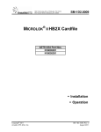
MICROLOK II
Addendum to Version 2.5 Service Manuals
ECode and i-Lok
Features Description
COPYRIGHT © 2002
Union Switch & Signal Inc.
December 2002
Original
Proprietary Notice
This document and its contents are the property of Union Switch & Signal Inc.
(hereinafter US&S). This document has been furnished to you on the following
conditions: no right or license under any patents or any other proprietary right in
respect of this document or its content is given or waived in supplying this
document. This document or its content are not to be used or treated in any manner
inconsistent with the rights of US&S, or to its detriment, and are not to be copied,
reproduced, disclosed to others, or disposed of except with the prior written consent
of US&S.
Important Notice
US&S constantly strives to improve our products and keep our customers apprised
of changes in technology. Following the recommendations contained in the attached
service manual will provide our customers with optimum operational reliability. The
data contained herein purports solely to describe the product, and does not create any
warranties.
Within the scope of the attached manual, it is impossible to take into account every
eventuality that may arise with technical equipment in service. Please consult your
local US&S sales representative in the event of any irregularities with our product.
We expressly disclaim liability resulting from any improper handling or use of our
equipment, even if these instructions contain no specific indication in this respect.
We strongly recommend that only approved US&S spare parts be used as
replacements.
SM 6800E, Original (12/02)
i
Revision History
Revision History
ii
Revision
Date
Original
December
2002
Author
Nature of Revision
Review & Approval Date
Renamed SM 7101 to
SM 6800 E.
Incorporated ECO
139748-6 and made
editorial and format
changes.
SM 6800E, Original (12/02)
TABLE OF CONTENTS
1
INTRODUCTION ....................................................................................................................................................... 1-1
1.1
PURPOSE ................................................................................................................................................................ 1-1
1.2
SCOPE .................................................................................................................................................................... 1-1
1.3
PRODUCT TRADEMARKS ........................................................................................................................................ 1-1
1.4
OVERVIEW OF NEW FEATURES............................................................................................................................... 1-1
1.4.1
ECode Coded Track Circuit .......................................................................................................................... 1-1
1.4.2
i-Lok .............................................................................................................................................................. 1-1
1.4.3
Miscellaneous MICROLOK II Features........................................................................................................ 1-2
1.4.4
Comparison Tool ........................................................................................................................................... 1-2
2
ECODE CODED TRACK CIRCUIT............................................................................................................................ 2-1
2.1
ECODE CODED TRACK CIRCUIT CONTROL............................................................................................................. 2-1
2.2
ECODE CODED TRACK CIRCUIT PCB DESCRIPTION AND OPERATION ................................................................... 2-4
2.3
ECODE CODED TRACK CIRCUIT INTERFACE PANEL ............................................................................................... 2-7
2.4
ECODE CODED TRACK CIRCUIT INSTALLATION ..................................................................................................... 2-8
2.4.1
ECode Coded Track Circuit Board Keying Plug Installation ........................................................................ 2-8
2.4.2
ECode Coded Track Circuit Interface Panel Installation............................................................................... 2-9
2.5
ECODE CODED TRACK CIRCUIT SPECIFICATIONS .................................................................................................. 2-9
2.5.1
Track Circuit Length ................................................................................................................................... 2-10
2.5.2
Track Codes................................................................................................................................................. 2-10
2.5.3
Shunt Detection Times ................................................................................................................................ 2-20
2.5.4
Operating Parameters .................................................................................................................................. 2-20
2.6
ECODE CODED TRACK CIRCUIT WIRING DIAGRAMS ........................................................................................... 2-20
2.6.1
ECode Coded Track Circuit PCB Basic Interface Wiring........................................................................... 2-20
2.6.2
ECode Coded Track Circuit Interface Panel – Basic Track Wiring ............................................................ 2-22
2.6.3
Cab Signal Interface Panel Wiring with an ECode Coded Track Circuit Interface Panel ........................... 2-22
2.6.4
Quick Shunt Module Application and Installation ...................................................................................... 2-22
2.7
DISPLAYING THE ECODE CODED TRACK CIRCUIT BOARD STATUS ...................................................................... 2-26
2.7.1
Using the Front Panel Push Button.............................................................................................................. 2-26
2.7.2
Navigating the On-Line Menu System ........................................................................................................ 2-26
2.8
PERFORMING ECODE CODED TRACK CIRCUIT CHECKS AND ADJUSTMENTS ........................................................ 2-29
2.8.1
Configuring the ECode Coded Track Circuit Boards (ECODE.TRACK)................................................... 2-29
2.8.2
Displaying ECode Coded Track Circuit Operating Statistics...................................................................... 2-31
2.8.3
ECode Coded Track Circuit Checks and Adjustments ................................................................................ 2-33
2.9
PERFORMING ECODE CODED TRACK CIRCUIT TROUBLESHOOTING ..................................................................... 2-41
2.9.1
Troubleshooting an ECode Coded Track Circuit ........................................................................................ 2-42
2.9.2
ECode Coded Track Circuit Board Fuses.................................................................................................... 2-42
2.10 DEFINING AN ECODE CODED TRACK CIRCUIT BOARD ......................................................................................... 2-43
3
I-LOK OPERATION .................................................................................................................................................... 3-1
3.1
I-LOK SYSTEM OVERVIEW ..................................................................................................................................... 3-1
3.2
I-LOK SYSTEM DESCRIPTION .................................................................................................................................. 3-1
3.2.1
General Configuration ................................................................................................................................... 3-2
3.2.2
Color Light and Searchlight Lamp Driver Boards......................................................................................... 3-4
3.2.3
Isolated I/O Board ......................................................................................................................................... 3-8
3.2.4
Non-Isolated I/O Board ................................................................................................................................. 3-8
3.2.5
i-Lok Processor Control .............................................................................................................................. 3-11
3.2.6
Vital Cut-Off Relay ..................................................................................................................................... 3-12
3.3
I-LOK SYSTEM SPECIFICATIONS ........................................................................................................................... 3-12
3.3.1
System Operating Power ............................................................................................................................. 3-12
3.3.2
i-Lok System Cardfile Hardware Configuration ......................................................................................... 3-14
3.3.3
VCOR Relay................................................................................................................................................ 3-15
3.3.4
Environmental ............................................................................................................................................. 3-15
SM 6800E, Original (12/02)
i
Table of Contents
3.4
I-LOK COMPONENTS............................................................................................................................................. 3-15
3.4.1
i-Lok System Installation Component List.................................................................................................. 3-15
3.4.2
MICROLOK II/i-Lok Cardfile Plug-In Components .................................................................................. 3-16
3.4.3
Installing the i-Lok Cardfile Plug-Ins.......................................................................................................... 3-17
3.5
I-LOK CARDFILE ASSEMBLY AND MODULES ........................................................................................................ 3-20
3.5.1
i-Lok Assembly ........................................................................................................................................... 3-20
3.5.2
i-Lok Cardfile - Local I/O Connections....................................................................................................... 3-22
3.5.3
Typical i-Lok Wiring Diagrams .................................................................................................................. 3-35
3.5.4
MICROLOK II Compatibility ..................................................................................................................... 3-42
3.6
I-LOK CIRCUIT BOARD CONNECTIONS ................................................................................................................. 3-42
3.6.1
Color Light Lamp Driver PCBs................................................................................................................... 3-42
3.6.2
Searchlight Lamp Driver PCBs ................................................................................................................... 3-44
3.6.3
Isolated I/O PCBs ........................................................................................................................................ 3-46
3.6.4
Non-Isolated I/O PCBs................................................................................................................................ 3-48
3.7
NAVIGATING THE ONLINE I/O MENU ................................................................................................................... 3-50
3.7.1
Color Light/Searchlight Lamp Driver Boards ............................................................................................. 3-52
3.7.2
Isolated I/O Board ....................................................................................................................................... 3-53
3.7.3
Non-Isolated I/O Board ............................................................................................................................... 3-53
3.8
VIEWING I-LOK CIRCUIT BOARD STATUS ............................................................................................................ 3-54
3.8.1
Viewing the Color Light Lamp Driver Board Status................................................................................... 3-54
3.8.2
Viewing the Searchlight Lamp Driver Board Status ................................................................................... 3-55
3.9
CONFIGURING I-LOK CIRCUIT BOARDS ................................................................................................................ 3-55
3.9.1
Color Light and Searchlight Lamp Driver Boards....................................................................................... 3-56
3.10 DEFINING I-LOK I/O BOARDS............................................................................................................................... 3-63
3.10.1 Color Light Lamp Driver Board.................................................................................................................. 3-64
3.10.2 Searchlight Lamp Driver Board .................................................................................................................. 3-65
3.10.3 Isolated I/O Board ....................................................................................................................................... 3-66
3.10.4 Non-Isolated I/O Board ............................................................................................................................... 3-66
4
MISCELLANEOUS MICROLOK II FEATURES....................................................................................................... 4-1
4.1
CONFIGURATION FROM THE RESET MENU.............................................................................................................. 4-1
4.1.1
Reconfiguring the Lamp Driver/MICROTRAX Board................................................................................. 4-1
4.2
ACCESSING THE SERIAL TEST SELECTION FEATURES............................................................................................. 4-5
4.3
ACCESSING PC CARD INFORMATION ..................................................................................................................... 4-8
4.4
NEW MICROLOK II DEVELOPMENT SYSTEM MENU SELECTIONS ....................................................................... 4-9
4.4.1
MICROLOK II Development System Program Main Menu......................................................................... 4-9
5
COMPARISON TOOL FUNCTIONALITY ............................................................................................................ 5-1
5.1
OVERVIEW ............................................................................................................................................................. 5-1
5.1.1
MICROLOK II Applications......................................................................................................................... 5-1
5.1.2
Comparison Methods..................................................................................................................................... 5-4
5.2
SOFTWARE INSTALLATION ..................................................................................................................................... 5-4
5.2.1
Installation ..................................................................................................................................................... 5-4
5.2.2
Removing the Comparison Tool.................................................................................................................... 5-5
5.3
OPERATIONAL DESCRIPTION .................................................................................................................................. 5-5
5.3.1
Start up .......................................................................................................................................................... 5-5
5.3.2
Graphical User Interface................................................................................................................................ 5-6
5.3.3
Understanding the Comparison Results......................................................................................................... 5-8
APPENDIX A
FUNCTIONAL EQUIVALENCIES ........................................................................................................... 1
ALL APPLICATION SECTIONS ................................................................................................................................................ 1
INDIVIDUAL APPLICATION SECTIONS .................................................................................................................................... 2
Pragma.............................................................................................................................................................................. 2
Program ............................................................................................................................................................................ 2
Interface............................................................................................................................................................................ 3
Local................................................................................................................................................................................. 4
Comm ............................................................................................................................................................................... 5
Boolean Bits ..................................................................................................................................................................... 6
ii
SM 6800E, Original (12/02)
Table of Contents
NV.Boolean Bits .............................................................................................................................................................. 7
Numeric Variables............................................................................................................................................................ 8
NV.Numeric Variables................................................................................................................................................... 10
Attributes........................................................................................................................................................................ 11
Timer Bits....................................................................................................................................................................... 13
Coded Outputs................................................................................................................................................................ 15
Log ................................................................................................................................................................................. 18
Constants ........................................................................................................................................................................ 20
Arrays ............................................................................................................................................................................. 22
Configuration ................................................................................................................................................................. 24
Logic .............................................................................................................................................................................. 26
Tables ............................................................................................................................................................................. 27
Numeric.......................................................................................................................................................................... 28
SM 6800E, Original (12/02)
iii
Table of Contents
iv
SM 6800E, Original (12/02)
Introduction
1
Introduction
1.1
Purpose
This addendum to the MICROLOK II service manuals (2.5 release) is meant to acquaint the reader
with additional system features recently developed for the product.
The information in this addendum will be incorporated into the 3.0 release of the MICROLOK II
documentation (SM-6800A, SM-6800B, SM-6800C, and SM-6800D). Until that release, this
document will serve as the primary source of reference on the new features.
1.2
Scope
Separate chapters in this addendum will describe four major categories of product enhancements:
• ECode Coded Track Circuit
• i-Lok Operation
• Miscellaneous MICROLOK II Features
• Use of the Comparison Tool
Along with describing the product enhancements, this addendum will identify the particular
MICROLOK II manuals and sections impacted by the new information.
1.3
Product Trademarks
MICROLOK ®, MICROLOK ® II, ECode, and i-Lok are trademarks or registered trademarks of Union
Switch & Signal Inc.
Electro Code 4 ® (EC4) and Electro Code 5 ® (EC5) are registered trademarks of GE Transportation
Systems Global Signaling.
1.4
1.4.1
Overview of New Features
ECode Coded Track Circuit
The existing MICROLOK II product supports the MICROTRAX Coded Track Circuit, which is
designed to provide train detection and communications through the rails. ECode is another track
circuit option now available within MICROLOK II. ECode is compatible with the Electro Code®
family of products.
With the inclusion of ECode into the MICROLOK II product line, MICROLOK II is now capable of
communicating with both the MICROTRAX and the Electro Code® track circuits.
1.4.2
i-Lok
i-Lok is an extension of the MICROLOK II product line. The standard MICROLOK II card file is
designed to address many different types of applications, from very small applications to large,
complex applications. The i-Lok cardfile is designed to address intermediate signal applications.
SM 6800E, Original (12/02)
1-1
Introduction
Patterned after MICROTRAX, the i-Lok cardfile is designed to include:
•
a track circuit board (either MICROTRAX or ECode)
•
1 or 2 MICROTRAX Color Light or Searchlight Lamp Driver boards
•
1 mixed I/O board
With these I/O configurations, i-Lok is suited for intermediate and cut-section (repeater) locations.
1.4.3
Miscellaneous MICROLOK II Features
Chapter 4 of this addendum describes these additional MICROLOK II features:
•
Reset Configuration – Enables the user to adjust the track length for the MICROTRAX track board
and/or the lamp wattage on the LAMP16 driver board while in the reset menu.
•
Serial Testing - Enables users to view code and current data for carrier alignment. This branch of
the on-line menu enables you to generate test-signals to be used for testing attached serial
communication circuits.
•
Identifying PC cards - Enables users to identify the status location of the PC Card on the CPU front
panel display.
•
Chapter 4 also discusses the new selections available from the Development System Program main
menu.
1.4.4
Comparison Tool
The MICROLOK II Application Comparison Tool compares two MICROLOK II applications and
reports the differences between them. The Tool serves two purposes. First, it can compare an original
MICROLOK II application with its reverse-compiled application. The Comparison Tool can also
compare two different versions of a MICROLOK II Application. The Comparison Tool is a part of the
MICROLOK II Development System.
1-2
SM 6800E, Original (12/02)
Ecodes Coded Track Circuit
2
ECode Coded Track Circuit
The sections that follow describe the MICROLOK II product's ECode coded track circuit functionality.
2.1
ECode Coded Track Circuit Control
Summary:
Chapter 2 in SM-6800A describes the general application and functions
of the MICROLOK II interlocking control system. Section 2.3 in
SM-6800A describes MICROLOK II system configurations for
application types. The ECode coded track circuit feature is an
additional application type.
The new ECode coded track circuit option is compatible with all versions of Electro Code ®. ECode
consists of two elements: a track PCB and a track interface panel. The ECode PCB interfaces with
MICROLOK II’s CPU, where the functions of track messaging and train detection are performed.
Both the track PCB and the interface panel are dual units to handle two independent track circuits. The
interface panel is designed for compatibility with highway crossing audio overlay equipment and
provides secondary surge protection. It is functionally and mechanically equivalent to the Electro
Code 5® (EC5) track interface panel – TIP-2. ECode operates at a fixed receiver sensitivity of 0.5
amperes and circuits are adjusted at the transmitter via 10 selected output voltages ranging from 1.0 to
2.5 volts.
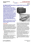
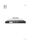
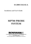
Two possible applications of ECode and/or MICROTRAX coded track circuits and interface panels are
illustrated in Figure 2-1 and Figure 2-2.
SM 6800E, Original (12/02)
2-1
ECode Coded Track Circuit
Coded Track
“C”
Coded Track
“A”
Coded Track
“B”
A
A
B
B
A
1
A
1
A
B
A
ECODE
INTERFACE
PANEL
B
ECODE
INTERFACE
PANEL
ECode Track
Interface
N17600101
Panel #1
ECode Track
Interface
N17600101
Panel #2
A
B
A
MICROLOK II
System
Cardfile
PUSH TO
SELECT
DISPLAY
MODE
5V ON
VCOR
A
1
B
2
C
3
D
6
VPP ON
7
CODE 5
T
3
L
R
M
A
R 7 5 M
B
ADJUS
T
UP
6
4
DOWN
8
2
POWER SUPPLY
X
M
I
T
TRACK B
RECEIVE
R
TRANSMITTE
R
TRANSMIT
0
LEVEL
ADJUST
STEAD
Y NORMA
L
OFF
REJEC
T
68332
MAIN
CPU
TRACK A
RECEIVE
R
TRANSMITTE
R
TRANSMIT
0
LEVEL
ADJUST
X
M
I
T
ECode TRACK
3
M
T
B
2
ACCEP
T
CODE 5
A
STEAD
Y NORMA
L
OFF
DOWN
UP
M
M
8
RESE
T
M
E
N
U
DISPLAY ON
CPU BOARD
R-CODE RECEIVED
T-CODE TRANSMITTED
R 7 5 M
8
RESET
TRACK CODE
REC
CURRENT
XMIT
VOLTAGE
XMIT
CURRENT
DISPLAY ON
CPU BOARD
5
ON LINE
TRACK CODE
REC
CURRENT
XMIT
VOLTAGE
XMIT
CURRENT
R-CODE RECEIVED
T-CODE TRANSMITTED
4
E
PUSH TO
SELECT
DISPLAY
MODE
8
2
TRACK A
RECEIVE
R
TRANSMITTE
R
TRANSMIT
0
LEVEL
ADJUST
STEAD
Y NORMA
L
OFF
6
4
8
2
X
M
I
T
TRACK B
RECEIVE
R
TRANSMITTE
R
TRANSMIT
0
LEVEL
ADJUST
STEAD
Y NORMA
L
OFF
X
M
I
T
ECode TRACK
N170
61301
RS-232
DTE
Figure 2-1 - MICROLOK II ECode Coded Track Circuit Configuration
2-2
SM 6800E, Original (12/02)
Ecodes Coded Track Circuit
Coded Track “C”
Coded Track “A”
MICROTRAX
Track Interface
Panel
N451835-010X
Coded Track “B”
10
m
hA
5
m
MI
CR
OT
RA
X
A
A
B
B
1
A
CODE
D
TRAC
K
CIRC
UIT
SYST
EM
B
ECODE
TRAC
K
INTE
RFAC
E
PANE
L
SERI
PART
AL
NO. NO.
INTERFACE
PANEL
U
U
NI
O
N
S
WI
TC
H
&
SI
G
N
ECode Track
Interface
N17600101
A
Master
MICROLOK
II System
Cardfile
5V ON
VCOR
B
PUSH TO
SELECT
DISPLAY MODE
+ SIGNALS
TRACK
RECEIVE
VALID MESSAGE
RECEIVED
TRACK
CODE
REC
CURRENT
XMIT VOLTAGE
MASTER
XMIT CURRENT
A
1
B
2
C
3
D
DISPLAY ON
CPU BOARD
R-CODE RECEIVED
T-CODE TRANSMITTED
4
CODE 5
5
E
ON LINE
T 3
6
VPP ON
7
RESET
8
L
M
E
N
U
R
B
TRANSMITTER
8
RECEIVE
VALID MESSAGE
RECEIVED
SLAVE
A
TRACK A
RECEIVER
+TRACK SIGNALS
-
RESET
M
M
R 7 5 M
2
0TRANSMIT
LEVEL ADJUST
STEADY
NORMAL
OFF
X
M
I
T
TRACK B
RECEIVER
ADJUST
UP
TRANSMITTER
DOWN
UP
ACCEPT
DOWN
REJECT
6
4
2
0TRANSMIT
LEVEL
ADJUST
STEADY
NORMAL
OFF
POWER
SUPPLY
68332
MAIN
CPU
8
TRACK
N451910
-0701
X
M
I
T
ECode
TRACK
N170
61301
RS-232
DTE
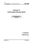
Figure 2-2 - MICROLOK II ECode Coded Track Circuit and MICROTRAX Track Circuit
Configuration
SM 6800E, Original (12/02)
2-3
ECode Coded Track Circuit
2.2
ECode Coded Track Circuit PCB Description and Operation
Summary:
Chapter 2 in SM-6800A describes the general application and functions
of the MICROLOK II interlocking control system. Section 2.5 in
SM-6800A describes the MICROLOK II system cardfile. The ECode
coded track circuit PCB is a new board that can be included in the
cardfile.
The ECode coded track circuit PCB is linked to both the CPU board and the track interface panel. The
CPU extracts information from the ECode PCB to determine track occupancy and track messages. The
interface panel terminates on the track and is also connected to the ECode coded track circuit PCB.
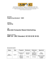
Table 2-1 describes the functions on the ECode coded track circuit board front panel.
Table 2-1 - Functions on ECode Front Panel
Fig. Ref.
1
Label
PUSH TO SELECT
DISPLAY MODE
Device
Momentary
pushbutton
switch
Purpose
Push once to display the transmitted and received
codes for tracks A and B.
Push twice to display the Received Current.
Push three times to display the Transmit Voltage.
Push four times to display the Transmit Current.
Push five times to return to the scrolling menu.
2
2-4
TRACK CODE
red LED
When lit, the transmitted and received codes will be
displayed on the CPU board.
REC CURRENT
red LED
When lit, the receiver current will be displayed on the
CPU board. Range from 0.0 to 3.6 amps in 0.1 amp
increments.
XMIT VOLTAGE
red LED
When lit, the transmit voltage will be displayed on the
CPU board. Range from 1.0 to 2.5 volts, dependent on
rotary switch position.
XMIT CURRENT
red LED
When lit, the transmit current will be displayed on the
CPU board. Range from 0.0 to 6.0 amps in 0.1 amp
increments.
3
TRACK A,
RECEIVER
green LED
When lit, indicates that the received current is greater
than 0.5 amps. Flashing LED represents the received
code.
4
TRACK A,
TRANSMITTER
red LED
When lit, indicates that the transmitter is turned on and
applying a DC signal to the track. Flashing LED
represents the transmitted code.
SM 6800E, Original (12/02)
Ecodes Coded Track Circuit
Fig. Ref.
Label
Device
Purpose
5
TRACK A
TRANSMIT LEVEL
ADJUST
10 position rotary
switch
Sets the transmitter output voltage, dependent on track
circuit length. Refer to adjustment table.
6
TRACK A
Three-position
toggle switch
NORMAL position: Board configured for normal track
circuit operation.
XMIT switch
STEADY position: Steady DC energy applied to Track A
at a level of 1.0 volt for troubleshooting.
OFF position: Transmitter A is turned off and receiver A
is turned on steady for troubleshooting.
7
TRACK B,
RECEIVER
green LED
When lit, indicates that the received current is greater
than 0.5 amps. Flashing LED represents the received
code.
8
TRACK B,
TRANSMITTER
red LED
When lit, indicates that the transmitter is turned on and
applying a DC signal to the track. Flashing LED
represents the transmitted code.
9
TRACK B
TRANSMIT LEVEL
ADJUST
10-position rotary
switch
Sets the transmitter output voltage, dependent on track
circuit length. Refer to adjustment table.
10
TRACK B
Three-position
toggle switch
NORMAL position: Board configured for normal track
circuit operation.
XMIT switch
STEADY position: Steady DC energy applied to Track B
at a level of 1.0 volt for troubleshooting.
OFF position: Transmitter B is turned off and receiver B
is turned on steady for troubleshooting.
The figure on the next page illustrates ECode coded track circuit PCB front panel layout.
SM 6800E, Original (12/02)
2-5
ECode Coded Track Circuit
1
PUSH BUTTON SWITCH
PUSH TO
SELECT
DISPLAY MODE
2
RED LEDs
TRACK CODE
REC. CURRENT
XMIT VOLTAGE
XMIT CURRENT
TYPICAL CPU BOARD
DISPLAY OF A
TRANSMITTED CODE
AND A RECEIVED CODE
DISPLAY ON
CPU BOARD
R = CODE RECEIVED
T = CODE TRANSMITTED
CODE 5
M
M
A
R 7 5M
B
T 3
TRACK A
3
GREEN LED
4
5
RED LED
ROTARY SWITCH
(10 POSITION)
RECEIVER
TRANSMITTER
6
8
0
4
2
TRANSMIT
LEVEL ADJUST
X
M
NORMAL I
T
OFF
STEADY
6
TOGGLE SWITCH
(3 POSITION)
7
8
9
GREEN LED
TRACK B
RECEIVER
RED LED
ROTARY SWITCH
(10 POSITION)
10 TOGGLE SWITCH
(3 POSITION)
TRANSMITTER
6
8
0
4
2
TRANSMIT
LEVEL ADJUST
X
M
NORMAL I
T
OFF
STEADY
ECode TRACK
Figure 2-3 - An ECode Coded Layout Track Circuit PCB - Front Panel
2-6
SM 6800E, Original (12/02)
Ecodes Coded Track Circuit
2.3
ECode Coded Track Circuit Interface Panel
Summary:
Chapter 2 in SM-6800A describes the general application and functions
of the MICROLOK II interlocking control system. Section 2.6 in
SM-6800A describes MICROLOK II auxiliary equipment. The ECode
Coded Track Circuit Interface Panel is additional auxiliary equipment.
The ECode coded track circuit interface panel carries all coded track communications between the
MICROLOK II system cardfile and the rails. The circuitry associated with the interface panel
minimizes interference from other signals on the rails. The US&S part number for the ECode coded
track circuit interface panel is N17600101.
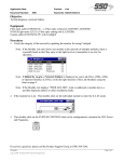
Figure 2-4 shows an ECode coded track circuit interface panel.
TRACK LEADS
TO ECODE BOARD
UPPER CONNECTOR
9 AMP FUSE
RES.
9 AMP FUSE
RES.
.25
.25
+ A
+ B
UNION SWITCH & SIGNAL
9 mh INDUCTOR
TRACK LEADS
9 mh INDUCTOR
ECODE INTERFACE PANEL
SURGE
N1700420
BOARD
S/N
2801030
P/N
N17600101
SURGE
N1700420
BOARD
UNION SW ITCH &
545INC
RUSSELL
SIGNAL
BATESBURG,
SC
ST
29006
MADE IN USA
Figure 2-4 - An ECode Coded Track Circuit Interface Panel
Panel components include a series connected inductor, a replaceable surge protection board with 6.0
volt transzorbs, two fuses, and a series 0.25 ohm resistor that can be shorted out. (Refer to the figure
on the next page.) These components are mounted on a 1/8 inch thick printed circuit board that is
made to be rack-mounted. External wiring to the track is made using two-way AAR terminal blocks.
Wiring to the cardfile is made through four terminals of a seven-way plug connector with cage clamp
terminations.
For cab signal applications, a 10 mh inductor (J702288) must be wired in series with the positive track
terminal of the track interface panel. This will block the 100 Hz cab signal from entering the ECode
coded track circuit receiver.
Figure 2-5 is a schematic of the ECode Coded Track Circuit Interface Panel.
SM 6800E, Original (12/02)
2-7
ECode Coded Track Circuit
JMP1
OUT
P1
ECode PCB
Output A "+"
ECode PCB
Output A "-"
1
IN
9mh
10A
R5
F1
0.25
Ohms
TRACK A+
9A
6.0V
Surge
Board
2
To Track +
Inductor
L1
F2
TRACK ATo Track -
JMP2
OUT
IN
9mh
ECode PCB
Output B "+"
ECode PCB
Output B "-"
4
10A
F3
TRACK B+
9A
R6
0.25
Ohms
6.0V
Surge
Board
5
To Track +
Inductor
L2
F4
TRACK BTo Track -
Figure 2-5 - ECode Coded Track Circuit Interface Panel Schematic
2.4
ECode Coded Track Circuit Installation
Summary:
Chapter 2 in SM-6800B describes MICROLOK II cardfile and circuit
board installation. Keying plug installation information for an ECode
Coded Track Circuit PCB is highlighted in the table that appears below.
Chapter 3 in SM-6800B describes the installation of MICROLOK II
system peripheral devices. Summarized installation information about
the ECode coded track circuit interface panel is highlighted in the table
that appears below.
2.4.1
ECode Coded Track Circuit Board Keying Plug Installation
Keying Plug Location
Printed Circuit Board
ECode coded track circuit
2-8
Part No.
1
2
3
4
N17063901
5
6
7
8
9
10
11
12
SM 6800E, Original (12/02)
Ecodes Coded Track Circuit
2.4.2
ECode Coded Track Circuit Interface Panel Installation
Wire resistance to and from the interface panel is critical. Adjustment tables, in section 2.8.3.1 of this
document, are based on maintaining the resistance of track leads and resistance to the seven-pin
connector to 0.1 ohms or less. Ultimate track circuit length is affected if greater than 0.1 ohms as
indicated in the adjustment tables.
The figure below illustrates specifications for mounting the ECode Coded track circuit interface panel:
4-1/4”
18”
5-5/16”
19”
5-3/16”
2-1/4”
Mounting Dimensions for ECode Interface Panel
2.5
ECode Coded Track Circuit Specifications
Summary:
Chapter 3 in SM-6800A provides operating specifications for the
various MICROLOK II printed circuit boards. The specifications for
the ECode coded track circuit will be detailed in a new section (a
preliminary version of which is provided below).
SM 6800E, Original (12/02)
2-9
ECode Coded Track Circuit
2.5.1
Track Circuit Length
Maximum Track Circuit Length
ECode to ECode
ECode to Electro Code 4® (EC4)
®
ECode to Electro Code 5 (EC5)
@ 3 ohms per 1000 ft. ballast
Up to 24,000 ft.
@ 3 ohms per 1000 ft. ballast
Track Codes
Vital Freight Codes
Time Between Leading Edges
N/A
224ms.
332ms.
488ms.
692ms.
820ms.
948ms.
Second Pulse Width
N/A
112ms.
112ms.
112ms.
112ms.
112ms.
112ms.
1250ms.
TO
1400ms.
First Pulse Width
112ms.
112ms.
112ms.
112ms.
112ms.
112ms.
112ms.
0
112ms.
224ms.
332ms.
Code
1
1&7
1&4
1&3
1&2
1&9
1&8
Up to 15,000 ft.
692ms.
820ms.
948ms.
2.5.2.1
@ 3 ohms per 1000 ft. ballast
488ms.
2.5.2
Up to 24,000 ft.
CODE 1
CODE 1 & 7
CODE 1 & 4
CODE 1 & 3
CODE 1 & 2
CODE 1 & 9
CODE 1 & 8
2-10
SM 6800E, Original (12/02)
Ecodes Coded Track Circuit
Second Pulse Width
N/A
224ms.
112ms.
112ms.
112ms.
112ms.
112ms.
1250ms.
TO
1400ms.
Time Between Leading Edges
N/A
224ms.
332ms.
488ms.
692ms.
820ms.
948ms.
692ms.
820ms.
948ms.
488ms.
First Pulse Width
224ms.
112ms.
224ms.
224ms.
224ms.
224ms.
224ms.
0
112ms.
224ms.
Code
1&5
1&7&5
1&4&5
1&3&5
1&2&5
1&9&5
1&8&5
Normal Code 5 - Freight
332ms.
2.5.2.2
CODE 1 & 5
CODE 1 & 7 & 5
CODE 1 & 4 & 5
CODE 1 & 3 & 5
CODE 1 & 2 & 5
CODE 1 & 9 & 5
CODE 1 & 8 & 5
SM 6800E, Original (12/02)
2-11
ECode Coded Track Circuit
Second Pulse Width
N/A
224ms.
224ms.
224ms.
112ms.
112ms.
112ms.
1250ms.
TO
1400ms.
948ms.
Time Between Leading Edges
N/A
224ms.
332ms.
488ms.
692ms.
820ms.
948ms.
692ms.
820ms.
First Pulse Width
224ms.
112ms.
112ms.
112ms.
224ms.
224ms.
224ms.
0
112ms.
224ms.
332ms.
Code
1&5
1&7&5
1&4&5
1&3&5
1&2&5
1&9&5
1&8&5
Alternating Code 5 - Freight
488ms.
2.5.2.3
CODE 1 & 5
CODE 1 & 7 & 5
CODE 1 & 4 & 5
CODE 1 & 3 & 5
CODE 1 & 2 & 5
CODE 1 & 9 & 5
CODE 1 & 8 & 5
2-12
SM 6800E, Original (12/02)
Ecodes Coded Track Circuit
Second Pulse Width
N/A
350ms.
350ms.
350ms.
112ms.
112ms.
112ms.
1250ms.
TO
1400ms.
948ms.
820ms.
Time Between Leading Edges
N/A
224ms.
332ms.
488ms.
692ms.
820ms.
948ms.
692ms.
488ms.
332ms.
First Pulse Width
350ms.
112ms.
112ms.
112ms.
350ms.
350ms.
350ms.
0
112ms.
Code
1&5
1&7&5
1&4&5
1&3&5
1&2&5
1&9&5
1&8&5
Long Code 5
224ms.
2.5.2.4
CODE 1 & 5
CODE 1 & 7 & 5
CODE 1 & 4 & 5
CODE 1 & 3 & 5
CODE 1 & 2 & 5
CODE 1 & 9 & 5
CODE 1 & 8 & 5
SM 6800E, Original (12/02)
2-13
ECode Coded Track Circuit
Second Pulse Width
N/A
304ms.
304ms.
304ms.
112ms.
112ms.
112ms.
1250ms.
TO
1400ms.
Time Between Leading Edges
N/A
224ms.
332ms.
488ms.
692ms.
820ms.
948ms.
692ms.
820ms.
948ms.
First Pulse Width
304ms.
112ms.
112ms.
112ms.
304ms.
304ms.
304ms.
0
112ms.
224ms.
332ms.
Code
1&M
1&7&M
1&4&M
1&3&M
1&2&M
1&9&M
1&8&M
Alternating Code M
488ms.
2.5.2.5
CODE 1 & M
CODE 1 & 7 & M
CODE 1 & 4 & M
CODE 1 & 3 & M
CODE 1 & 2 & M
CODE 1 & 9 & M
CODE 1 & 8 & M
2-14
SM 6800E, Original (12/02)
Ecodes Coded Track Circuit
Alternating Codes 5 and M
Second Pulse Width
N/A
264ms.
264ms.
264ms.
112ms.
112ms.
112ms.
1250ms.
TO
1400ms.
948ms.
820ms.
Time Between Leading Edges
N/A
224ms.
332ms.
488ms.
692ms.
820ms.
948ms.
692ms.
488ms.
332ms.
First Pulse Width
264ms.
112ms.
112ms.
112ms.
264ms.
264ms.
264ms.
0
112ms.
Code
1&5&M
1&7&5&M
1&4&5&M
1&3&5&M
1&2&5&M
1&9&5&M
1&8&5&M
224ms.
2.5.2.6
CODE 1 & 5 & M
CODE 1 & 7 & 5 & M
CODE 1 & 4 & 5 & M
CODE 1 & 3 & 5 & M
CODE 1 & 2 & 5 & M
CODE 1 & 9 & 5 & M
CODE 1 & 8 & 5 & M
SM 6800E, Original (12/02)
2-15
ECode Coded Track Circuit
Second Pulse Width
N/A
1250ms.
TO
1400ms.
Time Between Leading Edges
N/A
692ms.
820ms.
948ms.
0
112ms.
First Pulse Width
600ms.
488ms.
Code
6
Code 6
224ms.
332ms.
2.5.2.7
CODE 6
2-16
SM 6800E, Original (12/02)
Ecodes Coded Track Circuit
Second Pulse Width
N/A
92ms.
92ms.
92ms.
92ms.
92ms.
92ms.
600ms.
TO
748ms.
Time Between Leading Edges
N/A
190ms.
244ms.
298ms.
352ms.
406ms.
460ms.
406ms.
460ms.
0
1
1&7
1&4
1&3
1&2
1&8
1&9
First Pulse Width
92ms.
92ms.
92ms.
92ms.
92ms.
92ms.
92ms.
190ms.
244ms.
298ms.
352ms.
Code
Vital Transit Codes
92ms.
2.5.2.8
CODE 1
CODE 1 & 7
CODE 1 & 4
CODE 1 & 3
CODE 1 & 2
CODE 1 & 8
CODE 1 & 9
SM 6800E, Original (12/02)
2-17
ECode Coded Track Circuit
Second Pulse Width
N/A
208ms.
208ms.
208ms.
92ms.
92ms.
92ms.
600ms.
TO
748ms.
Time Between Leading Edges
N/A
190ms.
244ms.
298ms.
352ms.
406ms.
460ms.
190ms.
204ms.
244ms.
298ms.
352ms.
406ms.
460ms.
First Pulse Width
204ms.
92ms.
92ms.
92ms.
204ms.
204ms.
204ms.
0
Code
1&5
1&7&5
1&4&5
1&3&5
1&2&5
1&8&5
1&9&5
Normal Code 5 = Transit
92ms.
2.5.2.9
CODE 1 & 5
CODE 1 & 7 & 5
CODE 1 & 4 & 5
CODE 1 & 3 & 5
CODE 1 & 2 & 5
CODE 1 & 8 & 5
CODE 1 & 9 & 5
2-18
SM 6800E, Original (12/02)
Ecodes Coded Track Circuit
2.5.2.10 Code 6 - Transit
Time Between Leading Edges
N/A
Second Pulse Width
N/A
600ms.
TO
748ms.
0
6
First Pulse Width
496ms.
92ms.
190ms.
244ms.
298ms.
352ms.
406ms.
460ms.
496ms.
Code
CODE 6
SM 6800E, Original (12/02)
2-19
ECode Coded Track Circuit
2.5.3
Shunt Detection Times
Shunt Detection
Std. Shunt Detect Response
Std. Shunt Clear Response
Quick Shunt Detect
Option
3.7 - 6.3 seconds
11.2 - 12.6 seconds
100 msec (approximate)
2.5.4
Operating Parameters
Operating Parameters
Operating Temperature:
-40❡C to +70❡C
Supply Voltage:
Battery
9.8 - 16.2 VDC
System Supply Current Draw:
+5V
110 milliamps (ma)
+12V
43 ma
-12V
52 ma
Battery 180 ma average, 1.1 amps max.
Transmitter:
Output voltage to 1.25 ohms
1.0 to 2.5 volts DC
Output impedance
0.15 ohms
Current Measurement Range
0 to 6.0 amps
Receiver:
2.6
2.6.1
Input Impedance
0.15 ohms
Current Measurement Range
0 to 3.6 amps
ECode Coded Track Circuit Wiring Diagrams
ECode Coded Track Circuit PCB Basic Interface Wiring
The following diagram illustrates the ECode Coded Track Circuit PCB's basic interface wiring.
2-20
SM 6800E, Original (12/02)
Ecodes Coded Track Circuit
48-pin
Connector
P1-1
#12
#16
A2
#16
E2
C2
"A" Side
Track Interface
Panel
P1-2
Pin No.
A OUT+
ECode Track
Circuit PCB
N17063901
#12
#16
A4
#16
E4
A OUT-
C4
P1-4
#12
#16
A8
#16
E8
B OUT+
C8
"B" Side
P1-5
#12
#16
A10
#16
E10
B OUT-
C10
B12
N12
#16
C22
#16
A24
SEL+
SW1
SW2
SW3
SW4
SW5
SW6
Address
Select
PCB
GND
E32White
E30 Brown
C30 Red
A30 Orange
E28 Yellow
C28 Green
A28 Blue
A26 Black
CONNECTIONS TO
PCB ADDRESS
SELECT CIRCUITS
ECode Coded Track Circuit PCB - Basic Interface Wiring
SM 6800E, Original (12/02)
2-21
ECode Coded Track Circuit
2.6.2
ECode Coded Track Circuit Interface Panel – Basic Track Wiring
Figure 2.6-1 shows the basic wiring for an ECode track circuit around the insulated joints of a double
crossover. Two ECode Track boards inside the Microlok II cardfile drive the two ECode Track
Interface Panels. Note the polarity reversals across the insulated joint for each rail, this is done to
protect against a shorted insulated joint.
2.6.3
Cab Signal Interface Panel Wiring with an ECode Coded Track Circuit
Interface Panel
Figure 2.6-2 shows the basic wiring for an ECode track circuit with 100 Hz cab signaling. The Cab
Interface Panel is driven by the Coder Output and Cab Amplifier boards inside the Microlok II
cardfile. The output terminals on the Cab Interface Panel (1, 2, 3, & 4) connect directly to the rails.
An external 10 mh inductor must be placed in series with the TRACK A+ and TRACK B+ terminals
on the ECode Track Interface Panel. This inductor is required to block the 100 Hz cab signal, to keep
it from entering the ECode receiver. For more details on the wiring, installation, adjustment, and
programming of the Cab Signal Transmitter see Service Manuals SM-6800B and SM-6800C.
2.6.4
Quick Shunt Module Application and Installation
The optional quick shunt module (N451052-4601) is used in applications where an improved shunt
detection time is required. The quick shunt module reduces the detection time to approximately 100
milliseconds and contains circuitry for independent train detection on both sides of the insulated joint.
Two 8-way screw-lock connectors are provided for external wiring.
The two independent transmitters and receivers on this device should be connected to the ECode track
interface panel (N17004101) as shown in Figure 2.6-3. With this configuration, true shunt mode
operation is attained without the need for separate track termination leads. The detection zone is
limited to approximately 75 feet. For greater lengths, the transmitted and receiver track terminations
must be separated.
2-22
SM 6800E, Original (12/02)
Ecodes Coded Track Circuit
-
+
Insulated
Joints
+
Insulated
Joints
+
Insulated
Joints
Insulated
Joints
+
1
2
2
2
-
1
2
1
2
P1
1&2 4&5
A+
A-
P1
TRACK A+ TRACK A1
TRACK A+ TRACK A-
-
A B
2
2
1
2
P1
1&2 4&5
B+
B-
A+
TRACK B+ TRACK B-
A-
P1
TRACK A+ TRACK A-
ECode Track
Interface
Panels
N17600101
TRACK B+ TRACK B-
ECODE
INTERFACE
PANEL
1
TRACK A+ TRACK A-
ECode TRACK
INTERFACE PANEL
N17004101
J776616-1063
N17004101
J776616-1063
PUSH TO
SELECT
DISPLAY MODE
B-
TRACK B+ TRACK B-
TRACK B+ TRACK B-
ECODE
INTERFACE
PANEL
ECode TRACK
INTERFACE PANEL
5V ON
A B
B+
PUSH TO
SELECT
DISPLAY MODE
VCOR
TRACK CODE
TRACK CODE
REC CURRENT
REC CURRENT
XMIT VOLTAGE
XMIT VOLTAGE
XMIT CURRENT
1
Line-to-Line Arrester
USGA Blue
N451552-0101
A
1
B
2
C
3
D
4
E
5
ON LINE
CODE 5
T
6
VPP ON
7
RESET
8
CODE 5
M
A
T
R 7 5
M
B
R
TRACK A
RECEIVER
2
RESET
LEVEL ADJUST
X
M
I
T
2
UP
ACCEPT
DOWN
REJECT
6
4
2
0TRANSMIT
LEVEL ADJUST
X
M
I
T
TRANSMITTER
6
LEVEL ADJUST
STEADY
NORMAL
OFF
POWER SUPPLY
68332
MAIN
CPU
8
B
0TRANSMIT
TRACK B
RECEIVER
TRANSMITTER
DOWN
A
M
STEADY
NORMAL
OFF
TRACK B
RECEIVER
ADJUST
UP
M
7 5
TRANSMITTER
8
0TRANSMIT
STEADY
NORMAL
OFF
R
MICROLOK II
Cardfile
M
3
TRACK A
RECEIVER
TRANSMITTER
L
Line-to-GroundArrester
USGA Red
N451552-0201
DISPLAY ON
CPU BOARD
R-CODE RECEIVED
T-CODE TRANSMITTED
M
3
8
M
E
N
U
2
XMIT CURRENT
DISPLAY ON
CPU BOARD
R-CODE RECEIVED
T-CODE TRANSMITTED
X
M
I
T
ECode TRACK
4
8
2
0TRANSMIT
LEVEL ADJUST
STEADY
NORMAL
OFF
X
M
I
T
ECode TRACK
N170
61301
RS-232
DTE
ECode Track PCBs
Figure 2.6-1. Basic Wiring for a Double Crossover for ECode Track Circuit Interface Panels
SM 6800E, Original (12/02)
2-23
ECode Coded Track Circuit
+
Insulated
Joints
+
1
2
2
2
1
To MICROLOK II
Cardfile ECode
PCB
10mh
J702288
195J10
10mh
J702288
195J10
P1
TRACK A+ TRACK A-
2
TRACK B+ TRACK
BTRACK
B-
1
TRACK A+ TRACK A-
ECode Track
Interface Panel
N17600101
A
TRACK B+ TRACK B-
B
ECODE
INTERFACE
PANEL
ECode TRACK
INTERFACE PANEL
N17004101
J776616-1063
Cab Signal Interface Panel
N451835-0802 (100 Hz.)
1
3
5
2
4
E
3
2
E
4
7
6
11 13 15 17 19 21
10 12 14 16 18 20 22
1
W
W
Cab Signal
Output
Direction
Control
To ECode Track
Interface Panel P1
Terminals 1 & 2
9
8
PUSH TO
SELECT
DISPLAY MODE
5V ON
VCOR
To ECode Track
Interface Panel P1
Terminals 4 & 5
CODE
RATES
75
120
180
TRACK CODE
REC CURRENT
FLASHING
CODE RATE
TRANSMIT
CURRENT
LIMITER
XMIT VOLTAGE
XMIT CURRENT
1
Line-to-Line Arrester
USGA Blue
N451552-0101
A
1
B
2
4
D
CODE 5
5
E
ON LINE
T
6
VPP ON
7
RESET
8
3
M
M
A
R 7 5 M
B
TRACK A
RECEIVER
OUTPUTS
OUT 3
TRANSMITTER
8
2
RESET
0TRANSMIT
LEVEL ADJUST
STEADY
NORMAL
OFF
M
E
N
U
R
X
M
I
T
TRACK B
RECEIVER
ADJUST
UP
DOWN
6
4
UP
ACCEPT
REJECT
Line-to-Ground Arrester
USGA Red
N451552-0201
ECode Track PCB
POWER SUPPLY
68332
MAIN
CPU
8
2
OUT 4
DIRECTION
EAST
WEST
STEADY
CARRIER
EAST
NORMAL
TRANSMITTER
DOWN
MICROLOK II
Cardfile
R-CODE RECEIVED
T-CODE TRANSMITTED
3
C
L
2
DISPLAY ON
CPU BOARD
WEST
0TRANSMIT
LEVEL ADJUST
STEADY
NORMAL
OFF
X
M
I
T
ECode TRACK
CODER
OUTPUT
N451910
-5801
CAB
AMPLIFIER
N451910
-6401
N170
61301
RS-232
DTE
Cab Amplifier PCB
Coder Output PCB
Figure 2.6-2. Basic Wiring for ECode Track Circuit with Cab Signaling
2-24
SM 6800E, Original (12/02)
Ecodes Coded Track Circuit
+
Insulated
Joints
+
1
2
A+
2
2
1
To MICROLOK II
Cardfile ECode
PCB
ECode Track
Interface Panel
N17600101
P1
A-
TRACK A+ TRACK A-
2
B+
B-
TRACK B+ TRACK
BTRACK
B-
1
TRACK A+ TRACK A-
A
TRACK B+ TRACK B-
B
ECODE
INTERFACE
PANEL
ECode TRACK
INTERFACE PANEL
N17004101
J776616-1063
2
2
1
1
REC. XMT. REC. XMT.
Track 1
+
3
Out 1
4
7
4
8
5
REC. XMT. REC. XMT.
Track 1
Track 2
Quick Shunt Unit N451052-4601
B+ B7
8
-
-
+
To MICROLOK II
Vital Input
12V
Battery
To ECode Track
Interface Panel P1
Terminals 1 & 2
PUSH TO
SELECT
DISPLAY MODE
VCOR
TRACK CODE
REC CURRENT
XMIT VOLTAGE
XMIT CURRENT
1
A
Line-to-Line Arrester
USGA Blue
N451552-0101
DISPLAY ON
CPU BOARD
2
B
Out 2
6
-
To MICROLOK II
Vital Input
D
4
CODE 5
5
E
ON LINE
T
6
VPP ON
7
RESET
8
3
A
R 7 5 M
B
TRACK A
RECEIVER
TRANSMITTER
2
RESET
0TRANSMIT
LEVEL ADJUST
STEADY
NORMAL
OFF
R
IN 3
IN 4
IN 5
IN 6
IN 7
IN 8
MICROLOK II
Cardfile
M
M
8
L
IN 1
IN 2
R-CODE RECEIVED
T-CODE TRANSMITTED
3
C
M
E
N
U
2
+
5
To ECode Track
Interface Panel P1
Terminals 4 & 5
5V ON
1
Track 2
X
M
I
T
TRACK B
RECEIVER
ADJUST
UP
IN 9
IN 10
IN 11
IN 12
IN 13
IN 14
IN 15
IN 16
TRANSMITTER
DOWN
6
4
UP
DOWN
8
2
0TRANSMIT
LEVEL ADJUST
ACCEPT
REJECT
Line-to-Ground Arrester
USGA Red
N451552-0201
ECode Track PCB
POWER SUPPLY
68332
MAIN
CPU
STEADY
NORMAL
OFF
X
M
I
T
ECode TRACK
IN 16
N170
61301
RS-232
DTE
IN 16 PCB
Figure 2.6-3. Basic wiring for ECode Coded Track Circuit with a Quick Shunt Unit
SM 6800E, Original (12/02)
2-25
ECode Coded Track Circuit
2.7
Displaying the ECode Coded Track Circuit Board Status
Summary:
Chapter 3 in SM-6800C describes the navigation to and selection of
menu options via the CPU board's front panel displays. Section 3.4 in
SM-6800C describes the options for the On-line Menu, which provides
access to administrative and diagnostic functions. There are five new
selections under the "DISPlay IO" option; one of them is for the ECode
coded track circuit board.
2.7.1
Using the Front Panel Push Button
By using the push button on the ECode coded track circuit PCB front panel, users can view the
transmitted/received codes, receive current, transmit voltage and transmit current for a selected ECode
coded track circuit board. Use the following procedure to view the available data:
1. Push once to display the transmitted and received codes for tracks A and B.
2. Push twice to display the Received Current.
3. Push three times to display the Transmit Voltage.
4. Push four times to display the Transmit Current.
5. Push five times to return to the scrolling menu.
2.7.2
Navigating the On-Line Menu System
The ECODe BoaRDS option lets users view the transmitted/received codes, receive current, transmit
voltage and transmit current for a selected ECode coded track circuit board. Use the following
procedure to select an ECode coded track circuit board and view the available data:
1. With ECOD|BRDS showing on the CPU board displays, toggle the MENU UP-DOWN switch to
the DOWN position.
2. The CPU board displays will show ECOD|BD#, indicating the selection of one of the installed
ECode coded track circuit boards.
3. To change the ECode coded track circuit board selection, toggle the MENU L-R switch as
necessary until the desired board number is indicated in the lower display.
4. Toggle the MENU UP-DOWN switch to the DOWN position. The CPU displays will show the
transmitted and received codes for the A track on the upper display, and for the B track on the
2-26
SM 6800E, Original (12/02)
Ecodes Coded Track Circuit
lower display. The left-most character will display "T" for transmit and "R" for receive, with the
three remaining characters displaying the actual code. If the ECode coded track circuit board's
XMIT switch is currently in the "STEADY" position, the display will show "STDY." Likewise,
if the XMIT switch is in the "OFF" position, the display will show "OFF." If no codes are being
transmitted or received, the displays will show only the "T" and "R" characters.
5. To display the received current from the display codes menu, toggle the MENU UP-DOWN switch
to the DOWN position. The CPU displays will show the received current for each track half. The
received current ranges from 0.0A to 3.6A. If the received current is greater then 3.6A then the
display will show "HIGH." Likewise, if the current is too low (negative), it will display "LOW."
If the XMIT switch is in the "STEADY" position, the display will be blank.
6. To display the transmit voltage for the receive current menu, toggle the MENU UP-DOWN switch
to the DOWN position. The CPU displays will show the transmitted voltage for each track half.
The transmit voltages are based on the 10-position rotary switch on the front of the ECode coded
track circuit board. The possible values are 1.0, 1.2, 1.5, 1.7, 2.0, 2.1, 2.2, 2.3, 2.4, and 2.5V. If
the value is unknown the display will show "x.x." If the XMIT switch is in the "STEADY"
position, the display will display 1.0V. If the XMIT switch is in the "OFF" position, the display
will be blank.
7. To display the transmitted current from the transmit voltage menu, toggle the MENU UP-DOWN
switch to the DOWN position. The CPU displays will show the transmitted current for each track
half. The transmitted current ranges from 0.0A to 6.0A. If the transmitted current is greater then
6.0A then the display will show "HIGH." Likewise, if the current is too low (negative), it will
display "LOW." If the XMIT switch is in the "OFF" position, the display will be blank.
Note:
If either half of the ECode coded track circuit board is
disabled, then the display will show "DSBL" no matter
which menu function is selected.
The illustration on the next page highlights the ECode selections on the On-line Menu:
SM 6800E, Original (12/02)
2-27
ECode Coded
Track Circuit
Boards
ECode Coded Track Circuit
2-28
SM 6800E, Original (12/02)
Ecodes Coded Track Circuit
2.8
Performing ECode Coded Track Circuit Checks and Adjustments
Summary:
Chapter 4 in SM-6800C describes how to configure circuit boards and
to view circuit board statistics through the MICROLOK II System
Development Tools. Chapter 6 in SM-6800C describes circuit board
checks and adjustments. Within the section dealing with system
configuration, a new subsection describes ECode coded track circuit
checks and adjustments (a preliminary version of which is provided
below).
2.8.1
Configuring the ECode Coded Track Circuit Boards (ECODE.TRACK)
Check/configure the ECode coded track circuit boards as follows:
NOTE
The following procedure can also be performed using the MICROLOK II CPU board front panel
controls and displays. Use of the MICROLOK II Development System program, however, is the
preferred method due to ease of operation and the details provided.
1.
With the system configuration displayed on the PC screen, click on one of the ECODE.TRACK
selection buttons. The ECode coded track circuit board configuration screen shown below will be
displayed. The screen shows the current configuration of the selected board, including the system
default settings.
SM 6800E, Original (12/02)
2-29
ECode Coded Track Circuit
2. Make certain that the Enable selection box at the top of the screen is checked. If necessary, click on
the Enable selection box to insert a check mark.
3. If the A track for the board is to be used, make certain that the Side “A” Enable box is checked. If
necessary, click on the Side A Enable selection box to insert a check mark.
4. Select the type of Code 5 required. Selections are "Standard," "Long," "Smart," and "Alternating."
Select by clicking on the down arrow to the right of the selection box, and then click on the desired
Code 5 type.
•
The type of Code 5 used is dictated by the installation. Standard, Long, and Smart Code 5
selections should be used for compatibility with existing equipment. Typically, new
installations should use Alternating Code 5
5. Select Code M support, if required. Click on the Code M selection box to insert a checkmark if
Code M support is required. Code M is supported only with Alternating Code 5 selected.
6. Select "Freight" of "Transit" Code Group. Select by clicking on the down arrow to the right of the
selection box and then click on the desired Code Group.
7. If side "B" is to be used, make certain that the side B "Enable" box is checked. If necessary, click
on the side B "Enable" selection box to insert a checkmark.
8. Proceed as in steps 4 through 6 above to configure side B of the ECode coded track circuit board.
9. When all configuration parameters for the ECode coded track circuit board have been set to the
desired values, click on the "Done" button at the lower left corner of the screen. A dialog box
similar to the one shown below then appears:
10. Click on the "Yes" button to save the configuration changes and complete the board configuration.
The system configuration selection screen will again be displayed on the PC screen.
11. Repeat steps 1 through 10 to configure any additional ECode coded track circuit boards.
2-30
SM 6800E, Original (12/02)
Ecodes Coded Track Circuit
2.8.2
Displaying ECode Coded Track Circuit Operating Statistics
The MICROLOK II executive collects operating statistics from the ECode coded track circuit boards
defined in the MICROLOK II application program. These statistics may be used during general
preventative maintenance and during troubleshooting to evaluate the operation of ECode coded track
circuits.
ECode coded track circuit board statistics can easily be viewed using the MICROLOK II Development
Tool. To display this information:
1. Go to the Development Tool main menu.
2. Click on the "Board Information" selection button.
3. Click on the ECODE.TRACK selection button for the desired ECode coded track circuit board.
Statistics for the selected board will be displayed and dynamically updated.
An example of the display is shown on the next page:
ECode Coded Track Circuit Status Screen
SM 6800E, Original (12/02)
2-31
ECode Coded Track Circuit
Each ECode coded track circuit board supports two "track halves." Each track half is physically
connected to one end of a track circuit. The following statistics are displayed for each track half:
•
Track code transmitted
This parameter indicates the track code(s) currently being sent out on the local end of the
connected track circuit.
•
Track code received
This parameter indicates the track code(s) currently being received from the remote end of the
connected track circuit. When no code is displayed the track circuit is shunted or the track code
from the other end is otherwise disrupted or no code is currently being sent from the remote end of
the track.
•
Last received pulse 1
This parameter indicates the length of pulse 1 in milliseconds in the last code received. If "0" is
displayed, no code was received. Comparing the length of this pulse with the standard length of
the transmitted pulse is useful in determining the condition of the track circuit ballast and the
operating margin of the track circuit.
•
Last received pulse 2
This parameter indicates the length of pulse 2 in milliseconds in the last code received. If "0" is
displayed, the received code contained no readable second pulse was received. Comparing the
length of this pulse with the standard length of the transmitted pulse is useful in determining the
condition of the track circuit ballast and the operating margin of the track circuit.
•
Pulse 1 to pulse 2
This parameter indicates the time in milliseconds between the rising edge of pulse 1 and the rising
edge of pulse 2 as measured by the ECode coded track circuit receiver. Comparing this spacing
with the transmitted spacing is useful in determining the condition of the track circuit and the
operating margin of the track circuit.
•
Transmitter voltage
This parameter indicates the selected transmitter voltage in Volts.
•
Transmitter current
This parameter indicates the current in Amps that the transmitter is feeding into the rails. If this
current is significantly higher than normal, a shunted track circuit is indicated. If this current is
substantially lower than normal, a broken rail is indicated. If this current is zero or nearly zero, an
open track lead is indicated.
2-32
SM 6800E, Original (12/02)
Ecodes Coded Track Circuit
•
Receiver current
This parameter indicated the peak current in Amps detected while the last track code was received.
This parameter will typically be higher when a code containing Code 5 or Code M is received. It
will be slightly higher when receiving a two-pulse code. Typically, the minimum acceptable peak
current while receiving a code under low ballast conditions is 0.5 to 0.7 Amps. Under good ballast
conditions, the peak current may rise to 1.2 to 2.0 Amps depending on the length and ballast
conditions for the track circuit.
•
Measured receiver bias
This parameter is an indicator of ECode coded track circuit receiver integrity used by US&S
engineering. Typically, it should read between 90 and 110 percent.
•
Measured receiver 0 offset current
This parameter is an indicator of ECode coded track circuit receiver integrity used by US&S
engineering. Typically, it should read between 90 and 110 percent.
•
Receiver status
This parameter is not used and is always "0."
2.8.3
ECode Coded Track Circuit Checks and Adjustments
Setting up the ECode coded track circuit is a four-step process. This process involves:
•
Checking/adjusting the track circuit lengths according to the adjustment tables.
•
Checking the track circuit receiver current.
•
Performing the track circuit shunting test.
•
Performing the track circuit polarity check.
2.8.3.1
Setting the Transmitter Output Level
The transmitter output voltage must be properly adjusted to obtain a safe and reliable track circuit.
Refer to the appropriate adjustment table (provided later in this subsection) to determine the transmit
voltage level. There are three tables: one for ECode to ECode communications, one for ECode to
Electro Code 4® (EC4), and one for ECode to Electro Code 5® (EC5) communications. Select the
nearest track circuit length from the left column and go to the right to find the required Xmit voltage
level. Also note the correct settings for the jumpers on the track interface panel. For ECode to ECode
communications the jumpers should always be in the OUT position.
To display the transmit voltage, press the Display Mode push button three times until the Xmit Voltage
LED is lit. The CPU board will now display the current setting of the transmit voltage level. Use a
small screwdriver to adjust the rotary switches for track A and B until the proper voltage is displayed.
SM 6800E, Original (12/02)
2-33
ECode Coded Track Circuit
When communicating with an Electro Code 4® (EC4) or Electro Code 5® (EC5) at the other end of the
track circuit, use the tables for the correct settings on that equipment. On the following page is an
example of the correct settings for each case with a 10,000-foot track circuit:
Track Circuit
Settings
ECode to ECode
Xmit voltage to 1.2V and jumper to the OUT position.
ECode to Electro
Code 4® (EC4)
On ECode unit, Xmit voltage to 1.7V and jumper to the OUT position.
ECode to Electro
Code 5® (EC5)
On ECode unit, Xmit voltage to 1.5V and jumper to the IN position.
On Electro Code 4® (EC4) unit, set 2R Card Transmit Level Tap to
LOW and 7K Receiver Resistance board to Short. *
On Electro Code 5® (EC5) unit, set Xmit voltage to 1.5V and Receive
Reference to 0.50A.
* "Short" means to remove all of the receiver resistance by placing the shorting straps in
the "IN" position.
2-34
SM 6800E, Original (12/02)
Ecodes Coded Track Circuit
2.8.3.1.1
ECode to ECode Adjustment Table
ECode to ECode Adjustment Table
For minimum ballast of 3 Ω/1,000 ft.
.06 Ω Shunt
Recommended Settings
on ECode Board
Typical Receive Current
Amps Peak
Rotary
switch
position
XMIT
Voltage
1,000 ft
0
1.0V
2,000 ft
0
3,000 ft
Track Circuit
Length
Jumper on
Interface
Panel
Low
High
OUT
1.3A
1.4A
1.0V
OUT
1.2A
1.4A
0
1.0V
OUT
1.1A
1.3A
4,000 ft
0
1.0V
OUT
1.0A
1.3A
5,000 ft
0
1.0V
OUT
1.0A
1.3A
6,000 ft
0
1.0V
OUT
0.9A
1.2A
7,000 ft
0
1.0V
OUT
0.8A
1.2A
8,000 ft
1
1.2V
OUT
1.0A
1.5A
9,000 ft
1
1.2V
OUT
0.9A
1.5A
10,000 ft
1
1.2V
OUT
0.8A
1.4A
11,000 ft
2
1.5V
OUT
0.9A
1.7A
12,000 ft
2
1.5V
OUT
0.9A
1.7A
13,000 ft
3
1.7V
OUT
0.9A
1.9A
14,000 ft
3
1.7V
OUT
0.9A
1.9A
15,000 ft
3
1.7V
OUT
0.8A
1.9A
16,000 ft
4
2.0V
OUT
0.9A
2.1A
17,000 ft
4
2.0V
OUT
0.8A
2.1A
18,000 ft
4
2.0V
OUT
0.8A
2.0A
19,000 ft
5
2.1V
OUT
0.7A
2.1A
20,000 ft
6
2.2V
OUT
0.7A
2.2A
21,000 ft
7
2.3V
OUT
0.7A
2.2A
22,000 ft
8
2.4V
OUT
0.7A
2.3A
23,000 ft
9
2.5V
OUT
0.6A
2.4A
24,000 ft
9
2.5V
OUT
0.6A
2.3A
SM 6800E, Original (12/02)
JMP1 / JMP2
2-35
ECode Coded Track Circuit
2.8.3.1.2
ECode to Electro Code 4® (EC4) Adjustment Table
ECode to Electro Code 4® (EC4) Adjustment Table
For minimum ballast of 3 Ω/1,000 ft.
0.06 Ω
Shunt
Track
Circuit
Length
Recommended Settings on ECode Board
Rotary
switch
position
XMIT
Voltage
Jumper on
Interface Panel
JMP1 / JMP2
EC4 Recommended Settings
Typical
Receive Current
Amps Peak
Low
High
2 R Tap
7K
Resistor
Typical
Receive Current
Amps Peak
Low
High
1,000 ft.
1
1.2V
IN
1.4A
1.5A
Low
Short
1.12A
1.20A
2,000 ft.
1
1.2V
IN
1.2A
1.5A
Low
Short
1.02A
1.20A
3,000 ft.
1
1.2V
IN
1.1A
1.5A
Low
Short
0.94A
1.18A
4,000 ft.
1
1.2V
OUT
1.3A
1.8A
Low
Short
1.16A
1.47A
5,000 ft.
2
1.5V
OUT
1.2A
1.7A
Low
Short
1.29A
1.73A
6,000 ft.
2
1.5V
OUT
1.1A
1.7A
Low
Short
1.20A
1.70A
7,000 ft.
2
1.5V
OUT
1.0A
1.7A
Low
Short
1.11A
1.67A
8,000 ft.
3
1.7V
OUT
0.9A
1.7A
Low
Short
1.20A
1.92A
9,000 ft.
3
1.7V
OUT
0.9A
1.6A
Low
Short
1.12A
1.88A
10,000 ft.
3
1.7V
OUT
0.8A
1.6A
Low
Short
1.04A
1.85A
11,000 ft.
3
1.7V
OUT
0.7A
1.6A
Low
Short
0.97A
1.82A
12,000 ft.
6
2.2V
IN
0.9A
2.2A
Medium
Short
0.80A
1.84A
13,000 ft.
7
2.3V
IN
0.8A
2.2A
Medium
Short
0.78A
1.89A
14,000 ft.
9
2.5V
IN
0.7A
2.2A
Medium
Short
0.78A
2.03A
15,000 ft.
9
2.5V
IN
0.7A
2.2A
Medium
Short
0.73A
2.01A
2-36
SM 6800E, Original (12/02)
Ecodes Coded Track Circuit
2.8.3.1.3
ECode to Electro Code 5® (EC5) Adjustment Table
ECode to Electro Code 5® (EC5) Adjustment Table
For minimum ballast of 3 Ω/1,000 ft.
.06 Ω
Shunt
Recommended Settings
on ECode Board
EC5 Recommended
Settings
Typical
Receive Current
for ECode & EC5
Amps Peak
Track
Circuit
Length
Rotary
switch
position
XMIT
Voltage
Jumper on
Interface Panel
JMP1 / JMP2
Transmitter
Voltage
Receiver
Reference
Low
High
1,000 ft
0
1.0V
OUT
1.0V
0.50A
1.3A
1.4A
2,000 ft
0
1.0V
OUT
1.0V
0.50A
1.2A
1.4A
3,000 ft
0
1.0V
OUT
1.0V
0.50A
1.1A
1.3A
4,000 ft
0
1.0V
OUT
1.0V
0.50A
1.0A
1.3A
5,000 ft
0
1.0V
OUT
1.0V
0.50A
1.0A
1.3A
6,000 ft
0
1.0V
OUT
1.0V
0.50A
0.9A
1.2A
7,000 ft
0
1.0V
OUT
1.0V
0.50A
0.8A
1.2A
8,000 ft
2
1.5V
IN
1.5V
0.50A
0.8A
1.4A
9,000 ft
2
1.5V
IN
1.5V
0.50A
0.8A
1.4A
10,000 ft
2
1.5V
IN
1.5V
0.50A
0.7A
1.4A
11,000 ft
2
1.5V
OUT
1.5V
0.50A
0.9A
1.7A
12,000 ft
2
1.5V
OUT
1.5V
0.50A
0.9A
1.7A
13,000 ft
4
2.0V
IN
2.0V
0.50A
0.8A
1.8A
14,000 ft
4
2.0V
IN
2.0V
0.50A
0.7A
1.7A
15,000 ft
4
2.0V
IN
2.0V
0.50A
0.6A
1.7A
16,000 ft
4
2.0V
OUT
2.0V
0.50A
0.9A
2.1A
17,000 ft
4
2.0V
OUT
2.0V
0.50A
0.8A
2.1A
18,000 ft
4
2.0V
OUT
2.0V
0.50A
0.7A
2.0A
19,000 ft
9
2.5V
IN
2.5V
0.50A
0.6A
2.0A
20,000 ft
9
2.5V
IN
2.5V
0.50A
0.6A
2.0A
21,000 ft
7
2.3V
OUT
2.5V
0.50A
0.7A
2.2A
22,000 ft
8
2.4V
OUT
2.5V
0.50A
0.7A
2.3A
23,000 ft
9
2.5V
OUT
2.5V
0.50A
0.6A
2.4A
24,000 ft
9
2.5V
OUT
2.5V
0.50A
0.6A
2.3A
SM 6800E, Original (12/02)
2-37
ECode Coded Track Circuit
2.8.3.1.4
Track Wire Resistance Influence On Maximum Track Circuit Length
ECode adjustment tables are based on a generally conservative standard for minimum ballast of 3
Ω/M’, and track leads at each end of 0.1 Ω or a total of 0.2 Ω combined for both ends. Number 6 wire
is commonly used for track leads and has a resistance of 0.4 Ω/M’. Track leads of 125 feet at each
track circuit end of #6 wire add up to a total of 500 feet of wire and a total resistance of 0.2 Ω. For
track leads where the combined resistance exceeds 0.2 Ω ultimate track circuit length is reduced. The
table below illustrates the effect of increased lead resistance on limiting track circuit length for 3 Ω and
2 Ω minimum ballast.
Track Wire Resistance Influence
On Maximum Track Circuit Length
Combined Track
Lead Resistance
Maximum Track Circuit
Length For Minimum
Anticipated Ballast of 3 Ω/M’
Maximum Track Circuit
Length For Minimum
Anticipated Ballast of 2 Ω/M’
0.2 Ω
24,000 feet
14,000 feet
0.3 Ω
20,000 feet
12,000 feet
0.4 Ω
18,000 feet
11,000 feet
0.5 Ω
16,000 feet
10,000 feet
0.75 Ω
12,000 feet
7,000 feet
1.0 Ω
8,000 feet
5,000 feet
2.0 Ω
2,000 feet
1,000 feet
ECode may be used as a vital communications link and as such a track circuit is not involved. Instead
of connections through the rails, ECode units are linked together via line wire. For these applications,
it is recommended the track interface panel still be used because it provides the first line of defense for
lightning protection. Circuits are limited by a total of 4 Ω in the aggregate of all the connecting wire.
2.8.3.2
Displaying the Track Circuit Receive Current
The track Receive Current is a value that is used to determine whether a track circuit is properly
adjusted. The value represents the peak current of the received signal. A received current value or 0.5
Amps or higher is required before the system will recognize a valid code.
With the track circuit Transmit Voltage level set according to the tables, the received current value
should be between 0.6 and 2.4 amps. Dry ballast will produce a higher current and wet ballast will
give a lower value. The tables have taken this into consideration to provide a reliable track circuit.
The nominal current value is between 1.0 and 2.0 amps. If the current is greater than 2.4 amps the
track circuit may not shunt at 0.06 ohms (which represents the nominal resistance of the wheels and
axle on a car). In this case, the transmitter voltage level can be reduced at the other end of the track
circuit. If the transmit level is at the minimum of 1.0 volt, a 0.25 ohm resistor can be placed in series
2-38
SM 6800E, Original (12/02)
Ecodes Coded Track Circuit
with the track leads by setting the jumper JMP1/JMP2 on the track interface panel to the IN position.
This may be required to achieve 0.06 ohm shunting.
Track circuit Receive Current can be displayed on the MICROLOK II CPU board four-character
displays. The upper display shows the receive current for Track A and the lower display is for Track
B. To display the Receive Current, press the pushbutton switch at the top of the ECode Coded Track
Circuit Board twice. The red LED next to REC CURRENT should be lit. The CPU display will now
show the received current for Tracks A and B.
2.8.3.3 ECode Coded Track Circuit Shunting Test
The next step in the track circuit configuration process is to perform a shunting test using a 0.06 ohm
shunt. This test simulates an occupancy within the track circuit and checks the system’s response to
the installation of the shunt. The figure that follows shows the test installation.
This test is in accordance with FRA regulation 236.53, which requires that the track circuit system be
certified as properly responding to the presence of a shunt. If a track (A or B) has not been enabled in
the application software, the information for that track will not be displayed. This test is conducted
using the following procedure.
1. Display the TRACK CODE for the track circuit under test by pressing the push button switch on
the ECode board once. The red LED next to TRACK CODE should be lit.
2. Install a 0.06 ohm shunt across the track on the (A) side of the insulated joint. Verify that there is
NO Received Code on the upper display for Track A. The display will show an “R” with no code
next to it. Note that transmitter A will continue to transmit a code, and track B will continue to
receive a valid code. Leave the shunt in place for at least 30 seconds to make certain that the
occupancy indication remains constant.
3. Remove the shunt from the (A) side of the insulated joint. Verify that a valid code is being
received for Track A, such as “R4”.
4. Install a 0.06 ohm shunt across the track on the (B) side of the insulated joint. Verify that there is
NO Received Code on the upper display for Track B. The display will show an “R” with no code
next to it. Note that transmitter B will continue to transmit a code, and track A will continue to
receive a valid code. Leave the shunt in place for at least 30 seconds to make certain that the
occupancy indication remains constant.
5. Remove the shunt from the (B) side of the insulated joint. Verify that a valid code is being
received for Track B, such as “R8”.
6. If the shunting test fails, either the resistance of the shunt is higher than 0.06 ohms, or the
transmitter voltage level is too high, or the jumper on the Track Interface Panel is set incorrectly.
Refer to the adjustment tables to verify the proper settings. After any corrections, repeat steps 1
through 5.
SM 6800E, Original (12/02)
2-39
ECode Coded Track Circuit
0.06 Ohm Shunt - Install when directed during shunt test.
Polarity Test:
Swap Test Lead
Connections for
Sides A and B.
VOM
Set at 2.5 Volts
+
(TDC)
-
+
-
+
Side “A”
Side “B”
A+
A-
ECode
Track Interface
Panel
B+
B-
MICROLOK II Cardfile
Test Set-Up for ECode Coded Track Circuit Shunting Test and Polarity Check
2.8.3.4
2-40
Track Circuit Polarity Check
SM 6800E, Original (12/02)
Ecodes Coded Track Circuit
The rail polarity of each coded circuit must be checked to confirm that proper polarity is established
between adjacent track circuit blocks. The polarity of the track circuit feed changes polarity from one
side of an isolation joint to the other. This procedure requires a Simpson 260, TS-111, or an equivalent
volt-ohmmeter (VOM). See the figure on the previous page for the test set-up.
1. Set the VOM to the 2.5 volt (+DC) scale.
2. On one side of the isolation joint, connect the VOM (+) lead to the rail that is connected to the
TRACK A+ track signal feed. On the same side of the isolation joint, connect the VOM common
lead to the rail that is connected to the TRACK A- track signal feed.
3. Set up the system such that the ECode track circuit transmitter periodically transmits a code to the
rails. Monitor the VOM indication.
a. During intervals with no track circuit transmission, the VOM should indicate
0 volts.
b. During transmit intervals, the VOM should go above 0.5 volts
c. During receive intervals, the VOM indication should be considerably less than
the transmit voltage. The actual value depends on track circuit length.
4. If the meter readings are not as described in step 3, check the polarity of the track signal
connections between the cardfile and the ECode Track Interface Panel, and between the interface
panel and the rails. Correct any wiring discrepancies found.
5. Move the test lead connections to the opposite side of the isolation joint. Make certain that the
VOM (+) test lead is connected to the TRACK B+ rail and that the common test lead is connected
to the TRACK B- rail.
6. Observe the VOM voltage readings as the track circuit cycles the output signal. The reading
should be identical to those described in step 3. If the meter readings are not as described in step 3,
check the polarity of the track signal connections between the cardfile and the ECode Track
Interface Panel, and between the interface panel and the rails. Correct any wiring discrepancies.
Note: If the polarity test proves that the track leads must be reversed, do not do so until it is
determined that the intended sequence of polarity reversals for the entire block section will not be
violated.
2.9
Performing ECode Coded Track Circuit Troubleshooting
Summary:
Chapter 7 in SM-6800C describes procedures for system troubleshooting
and recovery. Within the section dealing with malfunction isolation, a
new subsection describes ECode coded track circuit checks and
adjustments (a preliminary version of which is provided below).
SM 6800E, Original (12/02)
2-41
ECode Coded Track Circuit
2.9.1
Troubleshooting an ECode Coded Track Circuit
The front panel of the ECode coded track circuit board contains a toggle switch for each track circuit to
enable a test mode to aid in troubleshooting the track circuits. Moving either switch from the
NORMAL position will disrupt track circuit communications. Placing the XMIT switch in the
STEADY position provides a constant 1.0 volt DC output, instead of the normal pulse code output.
Placing the switch in the OFF position disables the transmitter and enables the receiver full time.
If the received current is low and operation of the track circuit proves to be unreliable, the most likely
causes to investigate are:
•
A poor electrical connection somewhere within the track circuit. Possible causes are broken rail or
missing bond wires.
•
A leakage path between the two rails at some point in the track circuit. An example would be
shorted rail gage plates or conditions of low ballast.
A quick way to determine if the problem is an open circuit or a short-circuit is to examine the
transmitter output current. Use the pushbutton switch to display the XMIT CURRENT. If the
transmitter output current is 0.0A, then there is an open connection in the circuit. If the transmit
current is at or above its normal value, then either the ballast is very low or there is a short in the
circuit.
To troubleshoot a faulty track circuit, adjust the voltmeter to a low voltage scale (about 5V DC fullscale deflection). Set the XMIT switch to the STEADY position on the track circuit of interest. On
the far end of the same track circuit, set the XMIT switch to the OFF position to turn off the other
transmitter. Start at the end of the track circuit where the transmitter is turned on steady. Connect the
meter leads across the rails and test as if this were a simple DC track circuit, observe the correct rail
polarity. The problem area will be between points on the rail where a large drop in the voltage reading
is observed. Investigate to determine if there is an open circuit in the rail or a short circuit across the
rails.
2.9.2
ECode Coded Track Circuit Board Fuses
Fuses provide protection for the ECode coded track circuit board in the event that a lightning strike or
power surge exceeds the limiting capability of the Interface Panel. Refer to the fuse chart below:
Fuse Designation
Cartridge (FLNR9)
Manufacturer
Value
Quantity
Littelfuse®
9 Amp (Slo-Blo)
2
Littelfuse®
10 Amp
2
F2 and F4
Automotive Style (ATO-10)
F1 and F3
2-42
SM 6800E, Original (12/02)
Ecodes Coded Track Circuit
The 9-Amp cartridge fuse protects against high current surges such as downed power lines or welders
across the rails. The 10-Amp automotive-style fuse is the final level of protection against power
surges.
2.10
Defining an ECode Coded Track Circuit Board
Summary:
Chapter 3 in SM-6800D describes the procedure for defining I/O Boards in
a MICROLOK II Application. The interface section of a MICROLOK II
program defines all of the local and serial I/O for the MICROLOK II card
file. In the LOCAL subsection of the INTERFACE section, the physical
I/O cards are defined. The information below describes how to define an
ECode coded track circuit board.
SM 6800E, Original (12/02)
2-43
ECode Coded Track Circuit
Board Type: ECODE.TRACK
Address Class: 8 Bit VPA
A definition of this card looks like:
BOARD: <USER NAME>
[ADJUSTABLE | FIXED] ENABLE: <FLAG>
TYPE: ECODE.TRACK
TRACKA:
[TRACK.NAME: <name for track half>]
[[ADJUSTABLE | FIXED] ENABLE: <flag>;]
[[ADJUSTABLE | FIXED] CODE5.SUPPORT:
<STANDARD,LONG,SMART,ALTERNATING>;]
[[ADJUSTABLE | FIXED] CODEM.SUPPORT.ENABLED: <flag>;]
[[ADJUSTABLE | FIXED] CODE.GROUP.SELECT: <FREIGHT, TRANSIT>;]
TRACKB:
[TRACK.NAME: <name for track half>]
[[ADJUSTABLE | FIXED] ENABLE: <flag>;]
[[ADJUSTABLE | FIXED] CODE5.SUPPORT:
<STANDARD,LONG,SMART,ALTERNATING>;]
[[ADJUSTABLE | FIXED] CODEM.SUPPORT.ENABLED: <flag>;]
[[ADJUSTABLE | FIXED] CODE.GROUP.SELECT: <FREIGHT, TRANSIT>;]
Both track portions of the board must be defined.
If the TRACK.NAME statement is not present, the compiler will assign a default name of TRACK_x,
where x is A or B.
If an ENABLE statement is not supplied for half of the board, the compiler will provide a FIXED
default value of 0.
The CODE5.SUPPORT statement controls whether the CODE5 will be STANDARD, LONG,
SMART, or ALTERNATING. If no CODE5.SUPPORT statement is present, the compiler will
provide a FIXED default value of STANDARD.
The CODE.GROUP.SELECT can be either FREIGHT or TRANSIT. If the CODE.GROUP.SELECT
statement is not present, the compiler will provide a FIXED default value of FREIGHT.
The CODEM.SUPPORT.ENABLED can only be set under the following conditions or the compiler
will generate an error:
CODE.GROUP.SELECT: FREIGHT;
CODE5.SUPPORT: ALTERNATING
If the CODEM.SUPPORT.ENABLED statement is not present, the compiler will provide a FIXED
default value of 0.
The compiler also defines the following bits:
<board name>.TRACKx.ENABLED
2-44
(Read only)
SM 6800E, Original (12/02)
Ecodes Coded Track Circuit
<board name>.TRACKx.ADJUST.ENABLE
<board name>.TRACKx.CODEM.SUPPORT.ENABLED
<board name>.TRACKx.TRACK.FAILED
<board name>.TRACKx.CODE.1.OUT
<board name>.TRACKx.CODE.8.OUT
<board name>.TRACKx.CODE.9.OUT
<board name>.TRACKx.CODE.2.OUT
<board name>.TRACKx.CODE.3.OUT
<board name>.TRACKx.CODE.4.OUT
<board name>.TRACKx.CODE.7.OUT
<board name>.TRACKx.CODE.6.OUT
<board name>.TRACKx.CODE.5.OUT
<board name>.TRACKx.CODE.M.OUT
<board name>.TRACKx.CODE.1.IN
<board name>.TRACKx.CODE.8.IN
<board name>.TRACKx.CODE.9.IN
<board name>.TRACKx.CODE.2.IN
<board name>.TRACKx.CODE.3.IN
<board name>.TRACKx.CODE.4.IN
<board name>.TRACKx.CODE.7.IN
<board name>.TRACKx.CODE.6.IN
<board name>.TRACKx.CODE.5.IN
<board name>.TRACKx.CODE.M.IN
SM 6800E, Original (12/02)
(Read only)
(Read only)
(Read only)
(Read only)
(Read only)
(Read only)
(Read only)
(Read only)
(Read only)
(Read only)
(Read only)
(Read only)
(Read only)
2-45
ECode Coded Track Circuit
2-46
SM 6800E, Original (12/02)
i-Lok Operation
3
i-Lok Operation
The sections that follow describe the i-Lok System's functions.
3.1
i-Lok System Overview
Summary:
Chapter 2 in SM-6800A provides a general MICROLOK II system
description. A new section will be added to describe the i-Lok System (a
preliminary version of which is provided below).
The i-Lok system is a solid-state programmable, microprocessor-based system designed to control
wayside circuit applications in non-electrified territory. Primarily i-Lok is used to manage track
circuits providing end-to-end rail integrity, including detection of train shunt, faulty insulated joints or
broken rail. In addition to managing track circuits, this system allows the user to control signals, drive
relay outputs, and receive inputs from external sources.
3.2
i-Lok System Description
The i-Lok system is a solid-state programmable, microprocessor-based system designed to control
wayside track circuit applications in non-electrified territory, such as repeater or intermediate
locations.
An i-Lok consists of a cardfile assembly with plug-in modules and track interface panel/panels for the
operating tracks. Within the cardfile assembly are the plug-in modules specific to the requirements of
the location being designed. For example, certain locations may only require track circuit operation,
others may require signal lighting and others may require driving relays and/or receiving inputs. Each
individual location may combine portions or all of the options noted.
Features of the i-Lok system include:
•
Configurable software allowing a single "typical" program usable for all customer locations
including intermediate signals and repeater locations.
•
The executive and application software are uploaded and stored in flash PROM.
•
Uploading of software and troubleshooting is done through the MICROLOK II Development
System program.
•
Track circuits include either MICROTRAX or ECode type.
•
Adjustments for track circuits and signal lighting made with the aid of the CPU module.
•
Compatibility with highway crossing motion sensors/predictors without the need for external
blocking units.
SM 6800E, Original (12/02)
3-1
i-Lok Operation
The i-Lok unit can function independently, managing track circuits and controlling signals at an
intermediate location, or can be interfaced to a vital relay interlocking or a master controlling unit such
as a MICROTRAX End-of-Siding unit or a MICROLOK unit.
The i-Lok unit can be serially connected to other i-Lok units. MICROTRAX Coded Track units,
MICROTRAX End-of-Siding units, MICROLOK units or MICROLOK II units. This system allows
up to 16 units to be connected to one interlocking controller in a daisy chain configuration. Maximum
allowable cable length between two serially connected units is 50 ft. A modem is required for units that
are further than 50 ft. apart.
3.2.1
General Configuration
The i-Lok system cardfile contains the system’s central controlling logic and circuits that interface this
logic directly to external circuits, track interface panels for track circuits, relays, and signal aspects.
Logic and interface circuits are contained on the familiar Eurocard format plug-in printed circuit
boards. The system cardfile contains six card slots (although not all slots will be used in every
application) and a Vital Cut-Off Relay. Each installed circuit board plugs into a common backplane
motherboard. The backplane distributes circuit board operating power and enables the CPU board to
control and monitor other boards in the cardfile.
The specific circuit boards used in each i-Lok system are determined by the system application and the
boards available in the i-Lok cardfile. Typical configurations are recommended to optimize available
cardfile space. To simplify the cardfile configuration, the slots are restricted to a particular set of
boards. In addition, the board configuration must agree with the configuration defined in the
application logic software.
To prevent accidental insertion of a board into the wrong cardfile slot, each board is equipped with
male keying pins. These pins correspond with keying plugs installed in the associated backplane slot
connector. The keying pins are installed from the factory and will correspond to the boards assignment
for each slot.
To allow communications between the CPU board and the other boards in the cardfile, each board
must have its bus address configured in hardware. This is accomplished by nine of the pins on the
upper connector on the cardfile motherboard; this address assignment cannot be changed. In the
application software, boards must appear in a specific order to agree with the proper order of the board
addressing.
The table below describes the order that each board must be defined in the application, and it also
describes the slot position in the cardfile for each board.
Order of
Assignment
Slot Position
Board Assignment
1st
4
Track PCB - MICROTRAX or ECode
nd
1
Lamp Driver or Non-Isolated I/O
rd
2
Lamp Driver or Non-Isolated I/O
th
3
Isolated I/O
2
3
4
3-2
SM 6800E, Original (12/02)
i-Lok Operation
The CPU used in the i-Lok system is the same board and executive program that is used in the
MICROLOK II system. It comes with the same software features as a MICROLOK II, including the
PC interface with a Windows-based System Development program.
Refer to SM-6800A through D for specific CPU information.
System Power Supply
N16600301
CPU
N17061301
Slot No.
1 and 2
d
INTERNAL VCOR
US&S PN-150
or
TYPE B1, Relay
Part #A62-0125
Cardfile
Slot No.
1
2
3
PCB or Panel
d
Color Light Lamp Driver N451910-1501
or
Searchlight Lamp Driver N451910-7301
or
Non-Isolated I/O N451910-660X
3
Isolated I/O N451910-2101
4
MICROTRAX Track I/O N451910-070X
or
ECode N17063901
4
System Cardfile Functional Configuration
*For examples of what a typical cardfile looks like, refer to section 3.5.3 of this document.
d
SM 6800E, Original (12/02)
3-3
i-Lok Operation
3.2.2
Color Light and Searchlight Lamp Driver Boards
The i-Lok units can provide direct control of Color Light (Figure 3.2-1) or Searchlight (Figure 3.2-2)
signals. Signal lamp outputs are regulated and do not require the use of external adjustment resistors.
Adjustment of the lamps for proper lamp voltage/intensity can be accomplished at the i-Lok unit. (For
adjustment procedures, refer to "Color Light and Searchlight Lamp Driver Boards Signal Lamp
Adjustment" in subsection 3.9.1.3.)
The table below, describes the layout of the Color Light Lamp Driver PCB Front Panel.
Fig. Ref
Label
Device
1
INPUT 1
green LED
Monitor state of vital input #1. When lit, indicates
respective input is turned on.
2
INPUT 2
green LED
Monitor state of vital input #2. When lit, indicates
respective input is turned on.
3
LAMP ADJUST
Potentiometer
Multi-turn potentiometer, used to adjust the signal
lamp voltage for Head 1. CW increases the lamp
voltage, CCW decreases the lamp voltage.
(Screw Adjust)
4
HEAD 1
MASTER SIDE
red LED
Monitors state of the Head 1 red lamp drive. When lit,
indicates that the red aspect is turned on and it should
be lit. When flashing, the board is performing cold
filament test on the red aspect.
5
HEAD 1
MASTER SIDE
yellow LED
Monitors state of the Head 1 yellow lamp drive. When
lit, indicates that the yellow aspect is turned on and it
should be lit. When flashing, the board is performing
cold filament test on the yellow aspect.
6
HEAD 1
MASTER SIDE
green LED
Monitors state of the Head 1 green lamp drive. When
lit, indicates that the green aspect is turned on and it
should be lit. When flashing, the board is performing
cold filament test on the green aspect.
7
LAMP ADJUST
Potentiometer
(Screw Adjust)
3-4
Purpose
Multi-turn potentiometer, used to adjust the signal
lamp voltage for Head 2. CW increases the lamp
voltage, CCW decreases the lamp voltage.
8
HEAD 2
SLAVE SIDE
red LED
Monitors state of the Head 2 red lamp drive. When lit,
indicates that the red aspect is turned on and it should
be lit. When flashing, the board is performing cold
filament test on the red aspect.
9
HEAD 2
SLAVE SIDE
yellow LED
Monitors state of the Head 2 yellow lamp drive. When
lit, indicates that the yellow aspect is turned on and it
should be lit. When flashing, the board is performing
cold filament test on the yellow aspect.
10
HEAD 2
SLAVE SIDE
green LED
Monitors state of the Head 2 green lamp drive. When
lit, indicates that the green aspect is turned on and it
should be lit. When flashing, the board is performing
cold filament test on the green aspect.
SM 6800E, Original (12/02)
i-Lok Operation
1
2
3
4
INPUT 1
INPUT 2
LAMP ADJUST
5
6
HEAD 1
MASTER
SIDE
7
8
9
10
LAMP ADJUST
HEAD 2
SLAVE
SIDE
COLOR LIGHT
LAMP DRIVER
N451910
-1501
Figure 3.2-1. Color Light Lamp Driver PCB Front Panel Layout
SM 6800E, Original (12/02)
3-5
i-Lok Operation
The table below, describes the Searchlight Lamp Driver PCB front panel layout.
Fig. Ref
Label
Device
1
INPUT 1
green LEDs
Monitor state of vital input #1. When lit, indicates
respective input is turned on.
2
INPUT 2
green LEDs
Monitor state of vital input #2. When lit, indicates
respective input is turned on.
3
LAMP ADJUST
Potentiometer
Multi-turn potentiometer, used to adjust the signal
lamp voltage for Head 1. CW increases the lamp
voltage, CCW decreases the lamp voltage.
(Screw Adjust)
4
HEAD 1
red LEDs
Monitor state of the lamp drive for Head 1. When lit,
indicates that the signal mechanism is in the red
position. When flashing, the board is performing cold
filament test on the lamp.
5
HEAD 1
yellow LEDs
When lit, indicates that the Head 1 signal mechanism
is in the yellow position.
6
HEAD 1
green LEDs
When lit, indicates that the Head 1 signal mechanism
is in the green position.
7
LAMP ADJUST
Potentiometer
(Screw Adjust)
Multi-turn potentiometer, used to adjust the signal
lamp voltage for Head 2. CW increases the lamp
voltage, CCW decreases the lamp voltage.
8
HEAD 2
red LEDs
Monitor state of the lamp drive for Head 2. When lit,
indicates that the signal mechanism is in the red
position. When flashing, the board is performing cold
filament test on the lamp.
9
HEAD 2
yellow LEDs
When lit, indicates that the Head 2 signal mechanism
is in the yellow position.
10
HEAD 2
green LEDs
When lit, indicates that the Head 2 signal mechanism
is in the green position.
11
HEAD 1 GP
#6 Screw
Terminal
Provides the connection for the Green Repeater input
wire from the Searchlight mechanism for both HEAD 1
and HEAD 2.
HEAD 2 GP
3-6
Purpose
SM 6800E, Original (12/02)
i-Lok Operation
1
2
3
4
5
INPUT 1
INPUT 2
LAMP ADJUST
HEAD 1
6
7
8
9
LAMP ADJUST
HEAD 2
10
11
HEAD 1
GP
HEAD 2
GP
SEARCHLIGHT
LAMP DRIVER
N451910
-7301
Figure 3.2-2. Searchlight Lamp Driver PCB Front Panel Layout
SM 6800E, Original (12/02)
3-7
i-Lok Operation
3.2.3
Isolated I/O Board
The i-Lok units provide isolated inputs and outputs for remote equipment located outside of the
case/house in accordance with double break circuit design. Each isolated output can be used to operate
a switch lock coil and/or any 12-volt relay with a minimum of 150 ohms. The isolated module (Figure
3.2-3) contains four inputs and two outputs.
The table below describes the Isolated I/O PCB front panel layout. (Figure 3.2-3)
Fig. Ref
Label
Device
1
INPUT 1
QUICK RELEASE
green LED
Monitor the state of isolated input #1. When lit,
indicates respective input is turned on.
2
INPUT 2
TIMED RELEASE
green LED
Monitor the state of isolated input #2. When lit,
indicates respective input is turned on.
3
OUTPUT 1
LOCK RELEASE
red LED
4
INPUT 3
QUICK RELEASE
green LED
Monitor state of isolated input #3. When lit, indicates
respective input is turned on.
5
INPUT 4
TIMED RELEASE
green LED
Monitor state of isolated input #4. When lit, indicates
respective input is turned on.
6
OUTPUT 2
LOCK RELEASE
red LED
3.2.4
Purpose
Monitor state of isolated output #1. When lit, indicates
respective output is turned on.
Monitor state of isolated output #2. When lit, indicates
respective output is turned on.
Non-Isolated I/O Board
The i-Lok units provide logic inputs and outputs that do not require isolation from battery. These are
used for I/O within the i-Lok equipment case/house. Non-isolated I/O are typically used in an interface
to a relay-based interlocking control system. Two versions of this module (12-volt outputs driving
minimum 65-ohm coils, or 24-volt outputs driving minimum 130-ohm coils) are available. The nonisolated module (Figure 3.2-4) contains four inputs and four outputs.
The table below describes the Non-Isolated I/O PCB front panel layout. (Figure 3.2-4)
3-8
Fig. Ref
Label
Device
Purpose
1
INPUT 1 - 4
green LEDs
Monitor the state of vital non-isolated inputs #1 – 4.
When lit, indicates respective input is turned on.
2
OUTPUT 1 - 4
yellow LEDs
Monitor the state of vital non-isolated outputs #1 - 4.
When lit, indicates respective input is turned on.
SM 6800E, Original (12/02)
i-Lok Operation
1
2
3
4
5
6
INPUT 1
QUICK RELEASE
INPUT 2
TIMED RELEASE
OUTPUT 1
LOCK RELEASE
MASTER
INPUT 3
QUICK RELEASE
INPUT 4
TIMED RELEASE
OUTPUT 2
LOCK RELEASE
SLAVE
ISOLATED
I/O
N451910
-2101
Figure 3.2-3. Isolated I/O PCB Front Panel Layout
SM 6800E, Original (12/02)
3-9
i-Lok Operation
1
1
2
3
4
2
1
2
3
4
I
N
P
U
T
S
O
U
T
P
U
T
S
12V
NOM
NONISO
I/O
N451910
-6601
Figure 3.2-4. Non-Isolated I/O PCB Front Panel Layout
3-10
SM 6800E, Original (12/02)
i-Lok Operation
3.2.5
i-Lok Processor Control
The i-Lok system is managed by a single microprocessor and standard Executive software located on
the CPU module in flash memory. The CPU module is responsible for these basic functions:
•
Encoding and output of transmitted track codes
•
Decoding and processing of received track codes
•
Responding to loss of track codes (train shunts, broken rail, etc.)
•
Sending output commands to local devices (relays, signals, switch locks, etc.)
•
Reading input indications from local devices (relays, etc.)
•
Responding to signal lamp filament and Searchlight mechanism statuses
•
Controlling power to vital outputs
•
Processing on-site configuration inputs from user
•
Displaying information for track circuit setup and lamp adjustments
•
Performing internal diagnostics
•
Managing vital slave serial communications
CPU communication with all other modules is carried over a common data bus. Successful diagnostic
tests result in a 250Hz output to a conditional power supply on the System Power Supply module,
which energizes the VCOR (vital cut-off) relay. Vital or “critical” faults detected within the system
cause this relay to de-energize removing power from all outputs.
There are three operational modes associated with the i-Lok system: “Normal” mode, “Selective
Shutdown” mode, and “Full Shutdown” mode. If all diagnostic tests are passed, the CPU maintains
the system in “Normal” mode.
After a “critical” failure is detected, the unit will reset and go through the power-up sequence and
attempt normal operation. However, if five “critical” errors occur within 40 seconds of operational
time, the unit enters the “Selective Shut-Down” mode. In this mode, the VCOR is de-energized and all
Outputs become deactivated; however, track communications can continue. This feature will allow
trains to approach the affected location although the outputs are de-energized preventing signals from
being cleared.
If the unit is currently in the “Selective Shut-Down” mode and the unit detects five “critical” errors in
40 seconds of operational time, the unit enters the “Full Shutdown” mode and all operations including
track communications are stopped.
SM 6800E, Original (12/02)
3-11
i-Lok Operation
3.2.6
Vital Cut-Off Relay
All i-Lok units are equipped with a vital cut-off relay (VCOR) which controls power to the outputs.
The vital cut-off relay is mounted internally within the i-Lok unit. This relay is energized so long as
CPU internal diagnostics are passed. Any vital failure causes the relay to drop, thus removing power
from all outputs.
The i-Lok cardfile can be ordered with either a US&S PN-150B or a type B1, Relay Part # A62-0125
relay used for the VCOR.
When used with the MICROLOK II cardfile, the VCOR is externally mounted. For installation and
wiring information, refer to SM-6800A, Chapter 6 and SM-6800B, Section 3.2 “Vital Cut-Off Relay
(VCOR) Installation and Wiring.”
3.3
i-Lok System Specifications
Summary:
Chapter 3 in SM-6800A provides information about MICROLOK II
system specifications. A new section will be added to describe the i-Lok
system specifications (a preliminary version of which is provided below).
3.3.1
System Operating Power
Power Input to System Cardfile
Voltage
Range
Nominal
Voltage
Min. Sys.
Start-Up
Maximum
Ripple
9.5 to 16.5 VDC
12 VDC
11.5 VDC
0.5 V P-P
Current Draw
Determined by installation (number of signal
lamps and relays.)
Cardfile Power Supply Printed Circuit Board (N16660301)*
For System Cardfile
PCB 5V Internal Circuits
For System Cardfile
PCB 12V Internal Circuits
To VCOR Relay
+5V @ 3A
+12V @ 1A, -12V @ 1A
-12V into 400 - 500 ohm coil
*Not used to power vital or non-vital external devices or circuits
3-12
SM 6800E, Original (12/02)
i-Lok Operation
The table below is a list of the worst-case current draws for i-Lok system boards:
Board
Condition
+5V
+12V
-12V
COLOR.LIGHT N451910-1501
4 LEDs on
25ma.
16ma.
76ma.
SEARCH.LIGHT N451910-7301
4 LEDs on
30ma.
13.2ma.
90ma.
IN4.OUT4 N451910-660X
8 LEDs on
44ma.
60ma.
1ma.
IN4.OUT2.ISO N451910-2101
6 LEDs on
16.6ma.
28.2ma.
60ma.
The following tables describe lamp, input, and output specifications for each i-Lok PCB.
Vital Color Light Lamp Driver Printed Circuit Board
Lamp Specifications
US&S
Part No.
Signal Lamp
Voltage Range
N451910-1501
From 8.5V to
Battery -1Volt
Max. Battery
Voltage
Signal Lamp
Wattage Range
Number of Signals
18W - 25W
Six lamps total,
comprised of two
heads with three
signals per head
Voltage to
Ensure OFF State
Max. Sustained
Input Voltage
7.0V or less
16.2V
16.2V
Input Specifications
US&S
Part No.
Nom. Input
Voltage
N451910-1501
12V
Min. Voltage to
Ensure ON State
9.5V
Vital Searchlight Lamp Driver Printed Circuit Board
Lamp Specifications
US&S
Part No.
Signal Lamp
Voltage Range
N451910-7301
From 8.5V to
Battery -1 Volt
Max. Battery
Voltage
Signal Lamp
Wattage Range
Number of Signals
18W - 25W
Two lamps total,
comprised of two
heads with three
aspect searchlight per
head
Voltage to
Ensure OFF State
Max. Sustained
Input Voltage
7.0V or less
16.2V
16.2V
Input Specifications
US&S
Part No.
Nom. Input
Voltage
N451910-1501
12V
SM 6800E, Original (12/02)
Min. Voltage to
Ensure ON State
9.5V
3-13
i-Lok Operation
Vital IN4.OUT4 I/O Printed Circuit Boards
Input Specifications
US&S
Part No.
Nom. Input
Voltage
Min. Voltage to
Ensure ON State
Voltage to
Ensure OFF State
Max. Sustained
Input Voltage
N451910-6601
12V
9.5V
7.0V or less
16.2V
N451910-6602
12V
9.5V
7.0V or less
16.2V
Output Specifications
US&S
Part No.
Voltage VBATT
Range
Load Resistance
Range
Max. OFF
Voltage
Min. ON
Voltage
N451910-6601
12V
65 Ω - ∞
0.75V
11.5V
N451910-6602
24V
150 Ω - ∞
1.5V
23.5V
Vital IN4.OUT2.ISO I/O Printed Circuit Boards
Input Specifications
US&S
Part No.
Nom. Input
Voltage
Min. Voltage to
Ensure ON State
Voltage to
Ensure OFF State
Max. Sustained
Input Voltage
N451910-2101
12V
9.5V
7.0V or less
16.2V
Output Specifications
3.3.2
US&S
Part No.
Voltage VBATT
Range
Load Resistance
Range
Max. OFF
Voltage
Min. ON
Voltage (VBATT 12V)
N451910-2101
9.8 - 16.2V
240 Ω
500 Ω
750 Ω
1000 Ω
0.75V
15V
20V
23V
24V
i-Lok System Cardfile Hardware Configuration
Cardfile
Mounting
PCB
Mounting
Total
I/O
Slots
Vital Cutoff
Relay
I/O
Interface
Connections
Battery
Power
Connector
Std. 19” rack,
Shelf or wall
Eurocard
4
Internal to the
Cardfile
Three 22-way screw lock
terminals or two 22 and a 20way cage clamp terminals
AAR Terminal
Block
For MICROLOK II System cardfile hardware configuration, refer to Chapter 3 in SM-6800A.
3-14
SM 6800E, Original (12/02)
i-Lok Operation
3.3.3
VCOR Relay
Type
Contacts
Coil Resist.
(Ohms)
Pickup
Amps
Pickup
DC Volts
System
Voltage
US&S PN-150B
6FB
400Ω
0.0132A
5.3V
10V
6FB
500Ω
0.0121A
6.1V
10V
N322500-701
Type B1
Relay Part # A62-0125
J070205-1463
3.3.4
Environmental
System Cardfile Vibration
Operating Temperature Range
(All Units)
Humidity Limit
5 - 20HZ.: 0.05" P-P displacement
-40oC to +70oC
95% non-condensing
20 – 200Hz.: 1.0G Peak
Shock: 10G Peak
3.4
i-Lok Components
Summary:
Section 1.3 in Chapter 1 of SM-6800B details MICROLOK II system
hardware. Additional information will be added to identify i-Lok
components.
3.4.1
i-Lok System Installation Component List
i-Lok Major System Components
Name
i-Lok cardfile
US&S Part No.
N34600401 - US&S Relay and Buchanan I/O
connectors
Basic Function(s)
Houses all plug-in printed circuit boards
and the VCOR.
N34600402 - US&S Relay and Wago I/O
connectors
N34600403 - Type B1 Relay and Buchanan
I/O connectors
N34600404 - Type B1 Relay and Wago
I/O connectors
SM 6800E, Original (12/02)
3-15
i-Lok Operation
Name
US&S Part No.
Basic Function(s)
VCOR relay
N322500-701
(US&S PN-150B)
Switches power to all cardfile vital output
circuits under the control of the i-Lok CPU
board.
VCOR relay
J070205-1463
(Type B1 Relay Part # A62-0125)
Switches power to all cardfile vital output
circuits under the control of the i-Lok CPU
board.
3.4.2
MICROLOK II/i-Lok Cardfile Plug-In Components
MICROLOK II/i-Lok Cardfile Plug-In Components
Name
US&S Part No.
Color Light PCB
N451910-1501
Provides vital regulated lamp control to two
Color Light signal heads with both hot and
cold filament checks. Lamp voltage
adjustment is accomplished on board using
two potentiometers while monitoring the
lamp current on the CPU displays for both
18- and 25-watt lamps. Included on this
board are two isolated inputs that are
programmable by the system application.
Searchlight PCB
N451910-7301
Provides vital regulated lamp control to two
Searchlight signal heads with both hot and
cold filament checks and stuck-mechanism
checks in the red, yellow, and green
positions. Lamp voltage adjustment is
accomplished on board using two
potentiometers while monitoring the lamp
current on the CPU displays for both 18- and
25-watt lamps. Included on this board are
two isolated inputs that are programmable
by the system application.
Non-Isolated I/O PCBs
N451910-6601
(12V Inputs and 12V
Outputs)
Provides four vital inputs and four outputs
that are non-isolated type (common to N12).
There are two versions of this board:
N451910-6601 with 12-volt inputs and
outputs, and an N451910-6602 with 12-volt
inputs and 24-volt outputs.
N451910-6602
(12V Inputs and 24V
Outputs)
Isolated I/O PCBs
3-16
Basic Functions
N451910-2101 (12V)
Provides four vital isolated inputs and two
isolated outputs. Both the inputs and
outputs are nominal 12-volt type.
SM 6800E, Original (12/02)
i-Lok Operation
3.4.3
Installing the i-Lok Cardfile Plug-Ins
Installing the i-Lok system cardfile plug-ins is a four-step process. Each of the following steps must be
performed for each circuit board to be installed:
•
Selecting the appropriate cardfile slot for each circuit board (section 3.4.3.1).
•
Configuring the cardfile keying plugs for each circuit board (section 3.4.3.2).
•
Configuring the circuit board jumpers and firmware just prior to installation (section 3.4.3.3).
•
Installing the circuit boards (section 3.4.3.4).
3.4.3.1
i-Lok Circuit Board Installation Rules
Observe the following arrangement rules when installing i-Lok printed circuit boards into the card file:
•
Refer to the figure on the next page. All boards have assigned slots to be plugged into. The lower
connector is provided with a keying plug connector that mechanically keys each type of board to
the proper slot. These should not be changed or modified from the factory settings.
•
Power supply board N16600301 (without front panel) must be positioned behind the large blank
panel N34601301. This panel covers the VCOR and system power supply with the 5V ON and
VCOR LEDs visible in the holes provided on the panel.
•
All unused slots must be fitted with a blank shield panel so that the entire front face of the cardfile
is covered. Available blank panels include:
Single slot shield panel: N451850-2902
Double slot shield panel: N451850-2901
•
Secure the boards to the cardfile with the thumb-screws on the top and bottom of the front panel.
SM 6800E, Original (12/02)
3-17
i-Lok Operation
Cardfile PCB and Panel Installation Guidelines
System Power Supply
N16600301
CPU
N17061301
Slot No.
1 and 2
d
INTERNAL VCOR
US&S PN-150
or
TYPE B1, Relay
Part #A62-0125
Cardfile
Slot No.
1
2
3
PCB or Panel
d
Color Light Lamp Driver N451910-1501
or
Searchlight Lamp Driver N451910-7301
or
Non-Isolated I/O N451910-660X
3
Isolated I/O N451910-2101
4
MICROTRAX Track I/O N451910-070X
or
ECode N17063901
4
Front Panel Assembly
N34601301
Covers the VCOR
and Power Supply
Blank Panel
N451850-2902
or
N451850-2901
5V ON
VCOR
(VITAL CUT-OFF
RELAY)
d
3-18
Cardfile
Slot No.
1
2
3
4
SM 6800E, Original (12/02)
i-Lok Operation
3.4.3.2
i-Lok Circuit Board Keying Plug Installation
Cardfile Motherboard Keying Plug Locations
Keying Plug Location
Printed Circuit Board
Part No.
1
2
3
4
5
6
7
8
9
Color Light
N451910-1501
Searchlight
N451910-7301
Non-Isolated I/O
N451910-6601
Isolated I/O
N451910-2101
3.4.3.3
10
11
12
i-Lok PCB Jumper and Firmware Configurations
The CPU printed circuit board is the only board that contains jumpers and firmware to be configured.
The jumpers and firmware must be configured before the CPU printed circuit board is installed. For
more information on how the jumpers and firmware should be configured, refer to SM-6800B, section
2.2.3.1, “Configuring the CPU Board.”
3.4.3.4
Installing i-Lok Circuit Boards
US&S recommends that power is removed from the cardfile before removing or installing circuit
boards.
Use the following procedure to install the i-Lok plug-in circuit boards:
1. On the bottom front edge of the cardfile, there is a label that provides information as to which
boards are assigned to which slots. Use this as a guide when installing the circuit boards.
2. Hold the circuit board to be installed vertically in front of the cardfile.
3. Insert the board upper and lower edges into the plastic card guides inside the cardfile.
CAUTION
When installing any i-Lok circuit board into the card file, do not attempt
to force the board into the slot. Damage to the circuit board and
motherboard 96-pin connectors may result. If resistance is encountered
when installing a board, gently rock the board to engage the male and
female connectors. If the board still cannot be fully inserted into the card
slot, remove the board from the cardfile and attempt to determine the
source of the resistance.
SM 6800E, Original (12/02)
3-19
i-Lok Operation
4. Gently push the board into the cardfile until the board and cardfile connectors are fully engaged. If
the board has an integral front panel, make certain that the rear face of the front panel is flush
against the front of the cardfile.
5. If the board has an integral front panel, secure the board into position using the two retaining
screws attached to the front panel.
3.5
i-Lok Cardfile Assembly and Modules
Summary:
Section 2.1 in Chapter 2 of SM-6800B provides information and diagrams
to support the installation of MICROLOK II cardfiles. A new section will
be added to describe the i-Lok intermediate track circuit unit assembly (a
preliminary version of which is provided below).
3.5.1
i-Lok Assembly
The i-Lok cardfile is designed for use at intermediate operator locations. It consists of a cardfile
assembly and plug-in modules of various types. Included within the cardfile is a vital relay mounted in
the left-side and slots for six modules:
Slot
Module
Required ?
Left slot
Power Supply module
Always required
#1
Color Light module, or
All are design-dependent
Searchlight module, or
Non-Isolated I/O module
#2
Color Light module, or
All are design-dependent
Searchlight module, or
Non-Isolated I/O module
#3
Isolated I/O module
Design-dependent
#4
Track Interface module
Design-dependent
#5
CPU module
Always required
Located on the left-side of the unit on the upper sloping panel are AAR terminals for connecting the
input 12 volt battery power. The system will operate on a battery voltage range between 9.8 volts and
16.2 volts; however, to avoid premature loading of a recharging battery, the battery must be greater
than 11.5 volts when the system is powered up. When batteries are used, a constant voltage charger is
required. A transzorb-type surge suppressor is connected between the (+) and (-) posts to protect
against transcend over-voltage. The On/Off switch for the unit is located next to the battery terminals.
3-20
SM 6800E, Original (12/02)
i-Lok Operation
Located on the right side of the unit on the upper sloping panel are two 25-pin “D” connectors. These
are RS-485 and RS-232/423 serial data ports from the CPU module which can be programmed as vital
and non-vital links. These ports allow the unit to be serially connected to a MICROLOK or
MICROLOK II unit, a MICROTRAX unit, or other i-Lok units. The connectors are labeled PORT A
and PORT B and the pin-out on each connector is identical which facilitate daisy-chaining of serial
links. Table X below is a list of the signals and pins for the 2 serial ports.
Signal
COM1 TXD 485+
COM1 TXD 485COM1 RXD 485+
COM1 RXD 485COM1 CTS 485+
COM1 CTS 485COM1 DCD 485+
COM1 DCD 485COM1 RTS 485+
COM1 RTS 485COM1 TX CLK 485+
COM1 TX CLK 485COM1 RX CLK485COM1 RX CLK 485GND
COM3 TXD 232/423
COM3 RXD 232/423
COM3 CTS 232/423
COM3 DCD 232/423
COM3 RTS 232/423
COM3 REF
COM3 TX CLK 232/423
COM3 RX CLK 232/423
+12V
GND
25 D Connector Pin Number
4
16
8
6
3
14
9
21
19
17
7
5
18
20
1
25
12
11
23
24
13
15
2
22
10
Pin information for serial PORT A and B
All wire connections to the unit are made on three connectors located on the top of the unit. Two types
of connectors are available: screw lock plug connectors or cage clamp connectors. The screw lock
plug connectors are mounted on a common bar to allow simultaneous removal. The cage clamp
connectors are color-coded and are keyed to allow for simultaneous removal. Located on the upper
sloping panel is a label illustrating the correct wire connections for the application required.
SM 6800E, Original (12/02)
3-21
i-Lok Operation
3.5.2
i-Lok Cardfile - Local I/O Connections
On the i-Lok cardfiles, all of the I/O connections are made through three connectors on the top of the
cardfile. There are two options for these connectors using either screw lock or cage clamp style
connections. For proper connection, bare no more than 3/8” of conductor for either style of connector.
In the following table, there is a list of the I/O connectors that are used on the top of the cardfile and
are supplied with the cardfile when ordered.
Number of
Pins
Connector Mating End
US&S
Part Number
Manufacturer's
Part Number
Screw lock
Buchanan
22
Printed Circuit Board
J709146-0476
PCB3A22S
Cage Clamp
Wago
22
Socket End
Gray
J709146-1472
231-122/037-000
Cage Clamp
Wago
22
Socket End
Orange
J709146-1473
231-322/037-000
Cage Clamp
Wago
20
Socket End
Light Gray
J709146-1474
721-120/037-000
Wire Clamp Style
3.5.2.1
Screw Lock Terminals
TB1
TB2
1
2
3
6
4
5
7
8
9
10
12
11
13
14
16
17
15
18
20
1
19
22
21
1
22
2
6
3
4
5
7
8
9
10
12
11
13
14
16
17
15
18
20
19
22
22
21
1
2
5
3
6
4
7
8
9
10
11
12
13
14
15
16
17
18
19
1
20
21
22
22
1
The figure below shows Buchanan 22-way screw lock plug connectors. These connectors are designed
to hold up to #14 AWG wire. The three connectors are fastened to a fiberglass bar; this acts as a
keying mechanism for ease of removal and replacement.
TB3
Buchanan-Style 22-Way Screw Lock Connectors on the Top of the Cardfile
3.5.2.2
Cage Clamp Terminals
The following figure shows two Wago 22-way and one 20-way cage clamp connectors. These
connectors are designed to hold up to #12 AWG wire. Keying of these connectors is accomplished by
means of color, size and different spacing of each connector. TB1 is dark gray, 22-way pins on .197"
(5mm) centers. TB2 is light gray, 20-way pins on .197" (5mm) centers. TB3 is orange, 22-way pins
on .2" centers.
3-22
SM 6800E, Original (12/02)
TB2
1
2
3
6
4
7
5
8
9
11
10
12
15
13
14
16
19
17
20
1
18
22
21
1
22
4
2
3
6
7
5
8
9
10
11
12
13
15
TB1
14
16
17
20
18
20
19
1
2
3
6
4
7
5
8
9
11
10
12
15
13
14
16
19
17
20
1
18
21
22
22
1
i-Lok Operation
TB3
Wago-Style 22-Way and 20-Way Cage Clamp Connectors on the Top of the Cardfile
3.5.2.3
Output Pin Assignment
Connector pin-outs are listed in the following tables. In these tables, pin-outs are defined according to
the type of module assigned to a specific slot. Connections to the same terminal block will be different
depending on module placement in the unit, i.e., if a Color Light module is in I/O slot 1, it will be
wired to pins 18 through 15 and 12 through 9 for HEAD 1 and HEAD 2. If a non-isolated module is in
I/O slot 1, inputs 1 through 4 would be wired to pins 18 through 15 and outputs 1 through 4 are wired
to pins 12 through 9.
SM 6800E, Original (12/02)
3-23
i-Lok Operation
3.5.2.3.1
Color Light Lamp Driver Board
The Color Light Lamp Driver board can be used in either Slot #1 and/or Slot #2. Slot #1 is wired to
the left connector while slot #2 is wired to the center connector. The pin assignment for these two
connectors is identical for both the Buchanan and Wago style connector. Each connector has pin-outs
for two heads with red, yellow, green, and a positive common output for each head. Listed in the table
below is the pin-out for both the left and center connectors. The figure that follows the table shows
typical wiring for two heads from either slot #1 or #2.
Color Light Lamp Driver N451910-1501
Slot Number and
Connector Position
Pin-Out
Purpose
Slot #1
Left (TB1)
1(-) and 2(+)
3(-) and 4(+)
Isolated Input #2
Isolated Input #1
HEAD 2
9
10
11
12
HEAD 2
Common
Red
Yellow
Green
20(-) and 21(+)
12 Volt Isolated Source
1(-) and 2(+)
3(-) and 4(+)
Isolated Input #2
Isolated Input #1
HEAD 1
15
16
17
18
HEAD 1
Common
Red
Yellow
Green
Slot #2
Center (TB2)
3-24
SM 6800E, Original (12/02)
i-Lok Operation
W
SIGNAL
INSTRUMENT
HOUSE
E
SIGNAL
G
WDG
EDG
G
Y
WHG
EHG
Y
R
WRG
ERG
R
WNG
ENG
+
_
+_
22
21
20
19
18
17
16
15
14
13
12
11
10
9
8
7
6
5
4
3
2
1
+
_
Isolated 12 Volt Source on
Left (TB1) Connector Only
Isolated Input #2
Isolated Input #1
Typical Color Light Wiring for Left (TB1) or Center (TB2) Connectors
SM 6800E, Original (12/02)
3-25
i-Lok Operation
3.5.2.3.2 Searchlight Lamp Driver Board
The Searchlight Lamp Driver board can be used in either Slot #1 and/or Slot #2. Slot #1 is wired to the
left connector while slot #2 is wired to the center connector. The pin assignment for these two
connectors is identical for both the Buchanan and Wago style connector. Each connector has pin-outs
for two heads with lamp drive, mechanism control, and red, yellow, and green repeater control for each
head. Listed in the table that follows is the pin-out for both the left and center connectors. The figure
that follows the table shows typical wiring for two heads from either slot #1 or #2.
Searchlight Lamp Driver N451910-7301
Slot Number and
Connector Position
Pin-Out
Purpose
Slot #1
Left (TB1)
1(-) and 2(+)
3(-) and 4(+)
Isolated Input #2
Isolated Input #1
HEAD 2
8
9
10
11
12
HEAD 2
Red/Yellow Check Input (RP and YP)
Red/Green Check Output
Lamp-/Coil Common
Coil Drive (+/-)/Yellow Check Out
Lamp+
20(-) and 21(+)
12 Volt Isolated Source
1(-) and 2(+)
3(-) and 4(+)
Isolated Input #2
Isolated Input #1
HEAD 1
14
15
16
17
18
HEAD 1
Red/Yellow Check Input (RP and YP)
Red/Green Check Output
Lamp-/Coil Common
Coil Drive (+/-)/Yellow Check Out
Lamp+
Slot #2
Center (TB2)
3-26
SM 6800E, Original (12/02)
i-Lok Operation
W
SIGNAL
L-
E
SIGNAL
INSTRUMENT
HOUSE
M+
(G)
(Y)
W
X
A
B
P
(R-Y)
Q
(R-G)
WAG/WAEN
EBG/EBEN
NWAG/WAYP
NEBG/EBYP
WAEB
EBEB
WAGP
To Front
Panel HEAD
1 GP
WARP
M+
EBGP
To Front Panel
HEAD 2 GP
B
B
L-
(G)
(Y)
W
X
A
B
P
(R-Y)
Q
(R-G)
EBRP
+
_
+_
22
21
20
19
18
17
16
15
14
13
12
11
10
9
8
7
6
5
4
3
2
1
+ _
Isolated 12 Volt Source on
Left (TB1) Connector Only
Isolated Input #2
Isolated Input #1
Typical Searchlight Wiring for Left (TB1) or Center (TB2) Connectors
3.5.2.3.3 Non-Isolated I/O Board
The Non-Isolated I/O board can be used in either Slot #1 and/or Slot #2. Slot #1 is wired to the left
connector while slot #2 is wired to the center connector, and the pin assignment for these two
connectors is identical for both the Buchanan and Wago style connector. Each connector has pin outs
for 4 inputs and 4 outputs that are non-isolated and must be common to N12 battery. Listed in the
following table is the pin out for both the left and center connectors. The figure that follows the table
shows the typical wiring for four inputs and four outputs from either slot #1 or #2.
SM 6800E, Original (12/02)
3-27
i-Lok Operation
Non-Isolated I/O N451910-660X
Slot Number and
Connector Position
Slot #1
Left (TB1)
Slot #2
Center (TB2)
Pin-Out
Purpose
1,2,4,5,7,8,13,14
N12 (Battery Common B-)
9 thru 12
15 thru 18
Output #4 thru #1
Input #4 thru #1
20(-) and 21(+)
12 Volt Isolated Source
1,2,4,5,7,8,13,14
N12 (Battery Common B-)
9 thru 12
15 thru 18
Output #4 thru #1
Input #4 thru #1
N12
N12
N12
N12
N12
N12
N12
B12
B12
B12
B12
B12
B12
B12
B12
22
21
20
19
18
17
16
15
14
13
12
11
10
9
8
7
6
5
4
3
2
1
20
19
18
17
16
15
14
13
12
11
10
9
8
7
6
5
4
3
2
1
N12
22-Way Buchanan Screw Lock Connector
20-Way Wago Cage Clamp Connector
(Center Only)
Typical Non-Isolated I/O wiring for Left (TB1) or Center (TB2) Connectors
3-28
SM 6800E, Original (12/02)
i-Lok Operation
3.5.2.3.4
Isolated I/O Board
The Isolated I/O board is used in Slot #3 and is wired to the right top connector. The pin assignment
for this connector is identical for both the Buchanan- and Wago-style connector with pin-outs for four
inputs and two outputs. The inputs and outputs are isolated and require both a positive and negative
connection. Listed in the table below is the pin-out for the right connector. The figure that follows
shows typical wiring for four inputs and two outputs from the right top connector with the board in slot
#3.
Isolated I/O N451910-2101
Slot Number and
Connector Position
Slot #3
Right (TB3)
SM 6800E, Original (12/02)
Pin-Out
Purpose
6(-) and 7(+)
9(-) and 10(+)
12(-) and 13(+)
15(-) and 16(+)
18(-) and 19(+)
21(-) and 22(+)
Output #2 Relay Drive
Input #4
Input #3
Output #1 Relay Drive
Input #2
Input #1
3-29
i-Lok Operation
_
+
_
+
_
+
_
`
+
_
+
_
1
2
4
3
6
5
7
8
9
10
11
12
13
15
14
16
17
18
20
19
21
22
+
`
Typical Isolated Wiring for Right (TB3) Connector
3-30
SM 6800E, Original (12/02)
i-Lok Operation
3.5.2.3.5 ECode Coded Track Circuit Board
The ECode Track board is used in Slot #4 and is wired to the right-top connector. The pin assignment
for this connector is identical for both the Buchanan- and Wago-style connector with pin-outs for
Track A and Track B. Listed in the table below is the pin-out for the right connector. The figure that
follows the table shows typical wiring for two track circuits from the right top connector with the
board in slot #4.
ECode Track N17063901
Slot Number and
Connector Position
Pin-Out
Purpose
Slot #4
Right (TB3)
1(-) and 2(+)
3(-) and 4(+)
Track "B" Output
Track "A" Output
SM 6800E, Original (12/02)
3-31
i-Lok Operation
_
+
TRACK A
_
TRACK B
+
A
B
1
A
B
1
2
4
3
6
5
7
8
9
10
11
12
13
15
14
16
17
18
20
19
21
22
ECODE
INTERFACE
PANEL
`
Typical ECode Wiring for Right (TB3) Connector
3-32
SM 6800E, Original (12/02)
i-Lok Operation
3.5.2.3.6 MICROTRAX Coded Track Circuit Board
The MICROTRAX Track board is used in Slot #4 and is wired to the right-top connector. The pin
assignment for this connector is identical for both the Buchanan- and Wago-style connector with pinouts for the master and slave track circuits. Listed in the table below is the pin-out for the right
connector. The figure that follows the table shows typical wiring for two track circuits from the right
top connector with the board in slot #4.
MICROTRAX Track I/O N451910-070X
Slot Number and
Connector Position
Pin-Out
Purpose
Slot #4
Right (TB3)
1(-) and 2(+)
3(-) and 4(+)
Slave Track Output
Master Track Output
SM 6800E, Original (12/02)
3-33
3-34
22
21
20
19
18
17
16
15
14
13
12
11
10
9
8
7
6
5
4
3
2
1
U
TRACK INTERFACE PANEL
UNION SWITCH & SIGNAL
U
_
PART NO.
10mh
+
SERIAL NO.
5mh
10mh
MASTER
CODED TRACK CIRCUIT SYSTEM
5mh
_
MICROTRAX
UNION SWITCH & SIGNAL
SERIAL NO.
PART NO.
TRACK INTERFACE PANEL
CODED TRACK CIRCUIT SYSTEM
MICROTRAX
i-Lok Operation
+
SLAVE
Typical MICROTRAX Wiring for Right (TB3) Connector
SM 6800E, Original (12/02)
i-Lok Operation
3.5.3
Typical i-Lok Wiring Diagrams
On the i-Lok cardfiles, all of the I/O connections are made through three connectors on the top of the
Cardfile. There are two options for these connectors: Buchanan 22-way screw lock plug connectors,
or two Wago 22-way and one 20-way (center connector only) cage clamp connectors. For a better
description of these types of connectors, see Section 3.5.2, “i-Lok Cardfile - Local I/O Connections.”
The following diagrams show how to wire an i-Lok cardfile using either one of the connectors. For
example, the Color Light Lamp Driver Board wiring diagram is shown with Wago cage clamp
connectors, but you can use the Buchanan screw lock plug connectors with the Color Light Lamp
Driver Board as well.
Along with two different kinds of connectors that are used in an i-Lok cardfile, two different kinds of
track circuit controllers can also be used. Either an ECode Coded Track Circuit Board or a
MICROTRAX Coded Track Circuit Board can be used interchangeably in the cardfile setup. Both
track circuit controllers fit into the same slot on the cardfile, and they both have the same pin
assignments. (See section 3.5.2.3, "Output Pin Assignment.") Note that when using an ECode Coded
Track Circuit board, a single ECode Coded Track Circuit interface panel is used, and when using a
MICROTRAX Coded Track Circuit board, two MICROTRAX Coded Track Circuit interface panels
are used.
SM 6800E, Original (12/02)
3-35
i-Lok Operation
W
E
_
+
TRACK A
WT
W
SIGNAL
_
TRACK B
+
ET
E
SIGNAL
INSTRUMENT
HOUSE
G
WDG
EDG
G
Y
WHG
EHG
Y
R
WRG
ERG
R
WNG
ENG
1
A
B
1
2
3
4
7
6
5
9
11
10
15
TB2
12
13
14
16
17
21
19
20
18
22
1
4
2
6
3
7
5
8
9
10
11
12
15
13
14
16
17
20
18
19
1
2
3
7
4
6
8
5
9
11
10
12
15
13
14
16
17
18
21
19
20
22
TB1
8
ECODE
INTERFACE
PANEL
L
TB3
BATTERY
PORT A
POWER
ON
PORT B
OFF
i-Lok
5V ON
FAILOVER RELAY
INPUT 1
INPUT 1
INPUT 2
INPUT 2
ADJUST LAMP
ADJUST LAMP
HEAD 1
MASTER
SIDE
HEAD 1
MASTER
SIDE
PUSH TO
SELECT
DISPLAY MODE
TRACK CODE
REC CURRENT
CODED TRACK CIRCUIT SYSTEM
ELECTRONIC CARDFILE
XMIT VOLTAGE
XMIT CURRENT
DISPLAY ON
CPU BOARD
UNION SWITCH & SIGNAL
R-CODE RECEIVED
T-CODE TRANSMITTED
CODE 5
T
MADE IN USA
ADJUST LAMP
A
1
B
2
C
3
D
M
3
M
A
R 7 5
M
B
4
5
E
ON LINE
TRACK A
RECEIVER
ADJUST LAMP
6
VPP ON
7
RESET
8
TRANSMITTER
HEAD 2
SLAVE
SIDE
HEAD 2
SLAVE
SIDE
8
2
0TRANSMIT
LEVEL ADJUST
STEADY
NORMAL
OFF
RESET
X
M
I
T
TRACK B
RECEIVER
L
TRANSMITTER
6
(VCOR
MOUNTED
INTERNALLY)
4
8
2
0TRANSMIT
LEVEL ADJUST
STEADY
NORMAL
OFF
POWER SUPPLY
N16660301
COLOR LIGHT
LAMP DRIVER
N451910
-1501
COLOR LIGHT
LAMP DRIVER
N451910
-1501
X
M
I
T
ECode TRACK
M
E
N
U
R
ADJUST
UP
DOWN
UP
ACCEPT
DOWN
REJECT
68332
MAIN
CPU
N170
61301
RS-232
DTE
Color Light Lamp Driver and ECode Coded Track Circuit Boards
with Wago Connectors
3-36
SM 6800E, Original (12/02)
i-Lok Operation
W
E
_
+
TRACK A
WT
W
SIGNAL
_
TRACK B
+
INSTRUMENT
HOUSE
MECH
U
UNION SWITCH & SIGNAL
TRACK INTERFACE PANEL
PART NO.
CODED TRACK CIRCUIT SYSTEM
MICROTRAX
SERIAL NO.
1
2
3
7
4
6
8
5
9
10
11
UNION SWITCH & SIGNAL
TB2
12
13
16
17
18
21
19
20
22
1
4
2
6
3
7
5
8
9
10
11
12
15
13
14
16
20
17
18
19
1
2
3
7
4
6
8
5
9
11
10
12
15
13
14
16
17
21
19
20
18
22
TB1
U
5mh
5mh
R-G
TRACK INTERFACE PANEL
Y
PART NO.
G
CODED TRACK CIRCUIT SYSTEM
R-Y
SERIAL NO.
R-G
MICROTRAX
Y
15
G
10mh
10mh
MECH
14
R-Y
ET
E
SIGNAL
TB3
BATTERY
PORT A
POWER
ON
PORT B
OFF
i-Lok
5V ON
FAILOVER RELAY
CODED TRACK CIRCUIT SYSTEM
INPUT 1
INPUT 1
INPUT 2
INPUT 2
ADJUST LAMP
ADJUST LAMP
HEAD 1
HEAD 1
+
TRACK SIGNALS
RECEIVE
VALID MESSAGE
RECEIVED
MASTER
ELECTRONIC CARDFILE
UNION SWITCH & SIGNAL
A
1
B
2
C
3
D
4
5
E
MADE IN USA
ON LINE
ADJUST LAMP
ADJUST LAMP
HEAD 2
HEAD 2
+
TRACK SIGNALS
-
6
VPP ON
7
RESET
8
RECEIVE
VALID MESSAGE
RECEIVED
RESET
SLAVE
L
(VCOR
MOUNTED
INTERNALLY)
POWER SUPPLY
N16660301
HEAD1
GP
HEAD1
GP
HEAD2
GP
HEAD2
GP
SEARCHLIGHT
LAMP DRIVER
N451910
-7301
SEARCHLIGHT
LAMP DRIVER
N451910
-7301
M
E
N
U
R
ADJUST
UP
DOWN
UP
ACCEPT
DOWN
REJECT
TRACK
N451910
-0701
68332
MAIN
CPU
N170
61301
RS-232
DTE
Search Light Lamp Driver and MICROTRAX Coded Track Circuit Boards
with Wago Connectors
SM 6800E, Original (12/02)
3-37
i-Lok Operation
W
E
_
+
MASTER
WT
SLAVE
_
+
ET
_
+
5mh
5mh
10mh
_
+
10mh
_
+
U
UNION SWITCH & SIGNAL
TRACK INTERFACE PANEL
PART NO.
CODED TRACK CIRCUIT SYSTEM
SERIAL NO.
MICROTRAX
U
UNION SWITCH & SIGNAL
TRACK INTERFACE PANEL
SERIAL NO.
_
PART NO.
+
CODED TRACK CIRCUIT SYSTEM
MICROTRAX
_
+
_
TB2
1
2
6
3
7
4
5
8
9
10
11
12
15
13
14
16
17
18
20
21
19
22
1
2
3
4
7
5
6
8
9
10
11
15
13
14
12
16
17
20
19
TB1
18
1
2
3
6
4
7
5
8
9
10
11
15
12
13
14
16
20
17
21
18
22
19
+
TB3
BATTERY
PORT A
POWER
ON
PORT B
i-Lok
5V ON
FAILOVER RELAY
INPUT 1
QUICK RELEASE
INPUT 2
TIMED RELEASE
OUTPUT 1
LOCK RELEASE
MASTER
CODED TRACK CIRCUIT SYSTEM
INPUT 3
QUICK RELEASE
INPUT 4
TIMED RELEASE
OUTPUT 2
LOCK RELEASE
ELECTRONIC CARDFILE
+
TRACK SIGNALS
RECEIVE
VALID MESSAGE
RECEIVED
MASTER
SLAVE
UNION SWITCH & SIGNAL
A
1
B
2
C
3
D
4
5
E
MADE IN USA
ON LINE
+TRACK SIGNALS
-
6
VPP ON
7
RESET
8
RECEIVE
VALID MESSAGE
RECEIVED
RESET
SLAVE
L
M
E
N
U
(VCOR
MOUNTED
INTERNALLY)
POWER SUPPLY
N16660301
ISOLATED
I/O
N451910
-2101
R
ADJUST
UP
DOWN
UP
ACCEPT
DOWN
REJECT
TRACK
N451910
-0701
68332
MAIN
CPU
N170
61301
RS-232
DTE
Isolated I/O and MICROTRAX Coded Track Circuit Boards
with Wago Connectors
3-38
SM 6800E, Original (12/02)
i-Lok Operation
W
E
_
+
TRACK A
WT
_
TRACK B
+
ET
1
A
B
TB1
TB2
1
5
2
6
3
7
4
8
9
10
11
12
13
14
16
17
18
15
20
19
21
22
1
5
2
3
6
4
7
8
9
10
11
12
13
14
16
17
15
18
20
19
21
22
3
4
1
5
2
6
7
8
9
10
11
12
13
14
15
16
17
18
19
20
21
22
ECODE
INTERFACE
PANEL
TB3
BATTERY
PORT A
POWER
ON
PORT B
i-Lok
5V ON
FAILOVER RELAY
PUSH TO
SELECT
DISPLAY MODE
I
N
2 P
3 U
T
4 S
1
TRACK CODE
REC CURRENT
CODED TRACK CIRCUIT SYSTEM
XMIT VOLTAGE
ELECTRONIC CARDFILE
XMIT CURRENT
DISPLAY ON
CPU BOARD
UNION SWITCH & SIGNAL
R-CODE RECEIVED
T-CODE TRANSMITTED
CODE 5
MADE IN USA
1
2
3
4
T
3
M
A
R
7 5
M
B
8
2
5
6
VPP ON
7
RESET
8
0TRANSMIT
LEVEL ADJUST
RESET
X
M
I
T
L
TRANSMITTER
6
4
8
2
0TRANSMIT
LEVEL ADJUST
STEADY
NORMAL
OFF
NONISOLATED
I/O
4
ON LINE
TRACK B
RECEIVER
N451910
-6601
3
E
TRANSMITTER
NORMAL
OFF
N16660301
2
C
D
M
STEADY
POWER SUPPLY
1
B
TRACK A
RECEIVER
O
U
T
P
U
T
S
(VCOR
MOUNTED
INTERNALLY)
A
X
M
I
T
ECode TRACK
M
E
N
U
R
ADJUST
UP
DOWN
UP
ACCEPT
DOWN
REJECT
68332
MAIN
CPU
N170
61301
RS-232
DTE
Non-Isolated I/O and ECode Coded Track Circuit Boards
with Buchanan Connectors
SM 6800E, Original (12/02)
3-39
i-Lok Operation
E
_
MASTER
+
SLAVE
_
+
TB2
3
4
U
UNION SWITCH & SIGNAL
TRACK INTERFACE PANEL
PART NO.
CODED TRACK CIRCUIT SYSTEM
SERIAL NO.
1
5
6
7
8
9
10
12
11
14
13
17
15
16
18
19
20
21
22
UNION SWITCH & SIGNAL
MICROTRAX
U
5mh
5mh
TRACK INTERFACE PANEL
PART NO.
CODED TRACK CIRCUIT SYSTEM
SERIAL NO.
MICROTRAX
3
4
1
5
2
6
7
8
9
10
12
14
11
13
17
15
16
18
19
20
21
22
1
2
3
6
4
5
7
8
9
10
11
12
13
14
16
17
18
15
20
19
21
22
TB1
ET
10mh
10mh
WT
2
W
TB3
BATTERY
PORT A
POWER
ON
PORT B
i-Lok
5V ON
FAILOVER RELAY
CODED TRACK CIRCUIT SYSTEM
+
TRACK SIGNALS
RECEIVE
VALID MESSAGE
RECEIVED
MASTER
ELECTRONIC CARDFILE
UNION SWITCH & SIGNAL
A
1
B
2
C
3
D
4
5
E
MADE IN USA
ON LINE
+TRACK SIGNALS
-
6
VPP ON
7
RESET
8
RECEIVE
VALID MESSAGE
RECEIVED
RESET
SLAVE
L
M
E
N
U
NO VCOR
REQUIRED
POWER SUPPLY
TRACK
N16660301
N451910
-0701
R
ADJUST
UP
DOWN
UP
ACCEPT
DOWN
REJECT
68332
MAIN
CPU
N170
61301
RS-232
DTE
i-Lok Repeater with MICROTRAX Coded Track Circuit Board
and Buchanan Connectors
3-40
SM 6800E, Original (12/02)
i-Lok Operation
W
E
_
+
TRACK A
WT
_
TRACK B
+
ET
1
A
B
1
2
3
4
7
6
8
5
9
11
10
15
TB2
12
13
14
16
17
18
21
19
20
22
1
4
2
6
3
7
5
8
9
10
11
12
15
13
14
16
17
18
20
TB1
19
1
2
3
7
4
6
8
5
9
11
10
15
12
13
14
16
17
21
19
20
18
22
ECODE
INTERFACE
PANEL
TB3
BATTERY
PORT A
POWER
ON
PORT B
i-Lok
PUSH TO
SELECT
DISPLAY MODE
5V ON
FAILOVER RELAY
TRACK CODE
REC CURRENT
CODED TRACK CIRCUIT SYSTEM
XMIT VOLTAGE
ELECTRONIC CARDFILE
XMIT CURRENT
DISPLAY ON
CPU BOARD
UNION SWITCH & SIGNAL
R-CODE RECEIVED
T-CODE TRANSMITTED
CODE 5
T
MADE IN USA
3
R 7
5
M
1
B
2
3
C
D
M
M
A
4
5
E
A
ON LINE
B
TRACK A
RECEIVER
6
VPP ON
7
RESET
8
TRANSMITTER
8
2
0TRANSMIT
LEVEL ADJUST
STEADY
NORMAL
OFF
RESET
X
M
I
T
TRACK B
RECEIVER
L
TRANSMITTER
6
NO VCOR
REQUIRED
4
8
2
0TRANSMIT
LEVEL ADJUST
STEADY
NORMAL
OFF
POWER SUPPLY
N16660301
X
M
I
T
ECode TRACK
M
E
N
U
R
ADJUST
UP
DOWN
UP
ACCEPT
DOWN
REJECT
68332
MAIN
CPU
N170
61301
RS-232
DTE
i-Lok Repeater with ECode Coded Track Circuit Board and Wago Connectors
SM 6800E, Original (12/02)
3-41
i-Lok Operation
3.5.4
MICROLOK II Compatibility
All of the I/O boards that are used within the i-Lok cardfile, can be used with the MICROLOK II
cardfile. The Power Supply module and the CPU module in the i-Lok cardfile are the same modules
that are used in the MICROLOK II cardfile. The wiring connections for all of the boards that are used
in the i-Lok cardfile will be different when used in a MICROLOK II cardfile. Refer to SM-6800B for
the correct wiring practices of a MICROLOK II cardfile. Note that in a MICROLOK II cardfile,
boards can be used in any slot, unlike i-Lok cardfiles where slots are dedicated for specific boards.
3.6
i-Lok Circuit Board Connections
Summary:
Section 2.4 in Chapter 2 of SM-6800B describes and illustrates circuit
board connections to external circuits. A new subsection will be added to
illustrate the i-Lok circuit board connections. (Preliminary versions of
diagrams are presented in the following pages.)
3.6.1
Color Light Lamp Driver PCBs
The Color Light Lamp Driver board supports two three-aspect signal heads with lamps between 18 and
25 watts. The lamp driver is regulated B12 which is fed through a contact of the VCOR. Screw
adjustment for setting lamp voltage for each head is built onto the board, do not use any external
dropping resistors in the lamp circuit.
The Color Light Lamp Driver board has two isolated (double-break) inputs available that are defined
in the application.
Vital Color Light Lamp Driver Printed Circuit Board
Lamp Specifications
US&S
Part No.
Signal Lamp
Voltage Range
N451910-1501
From 8.5V to
Battery -1Volt
Max. Battery
Voltage
Signal Lamp
Wattage Range
Number of Signals
18W - 25W
6 Lamps, Comprised
of 2 Heads with 3
signals per Head
Voltage to
Ensure OFF
State
Max. Sustained
Input Voltage
7.0V or less
16.2V
16.2V
Input Specifications
3-42
US&S
Part No.
Nom. Input
Voltage
N451910-1501
12V
Min. Voltage
to Ensure ON
State
9.5V
SM 6800E, Original (12/02)
i-Lok Operation
48-pin
Connector
I/O
A2
+
A4
-
E2
+
E4
-
E8
Head 2 Regulator Out
Input #1
Input #2
N451910-1501
A10 Head 2 Red Lamp
C10 Head 2 Yellow Lamp
COLORLIGHT
LAMP
DRIVER
PCB
E10 Head 2 Green Lamp
E12 Head 1 Regulator Out
A14 Head 1 Red Lamp
C14 Head 1 Yellow Lamp
E14 Head 1 Green Lamp
B12
VCOR
Relay
E24 VCOR B12
C24 VCOR B12
C26 Battery -
N12
E26 Battery E22 Battery A22 GND
WIRE
JUMPER
A32 ADDRSEL 3
SEL+
SW1
SW2
SW3
SW4
SW5
SW6
Address
Select
PCB
SM 6800E, Original (12/02)
GND
E32 SEL+
E30 ADDRSEL 4
C30 ADDRSEL 5
A30 ADDRSEL 6
E28 ADDRSEL 7
C28 ADDRSEL 8
A28 ADDRSEL 9
A26 GND
CONNECTIONS TO
PCB ADDRESS
SELECT CIRCUITS
3-43
i-Lok Operation
3.6.2
Searchlight Lamp Driver PCBs
The Searchlight Lamp Driver board supports two search light mechanisms. Each signal can drive a
lamp rated between 18 and 25 watts. The lamp driver is regulated B12 which is fed through a contact
of the VCOR. Screw adjustment for setting lamp voltage for each head is built onto the board, do not
use any external dropping resistors in the lamp circuit. The wiring to the signal heads includes stuck
mechanism checks circuits for the red, yellow and green positions. Red and yellow repeater circuits
are wired through the 48 way connector on the back of the board. The green repeater circuit comes
onto the board through two screw connections on the front panel of the Searchlight board.
The Searchlight Lamp Driver board has two isolated (double-break) inputs available which are defined
in the application.
Vital Searchlight Lamp Driver Printed Circuit Board
Lamp Specifications
US&S
Part No.
Signal Lamp
Voltage Range
N451910-7301
From 8.5V to
Battery -1 Volt
Max. Battery
Voltage
Signal Lamp
Wattage Range
Number of Signals
18W - 25W
2 Lamps, Comprised
of 2 Heads with 3
aspects per Head
Voltage to
Ensure OFF
State
Max. Sustained
Input Voltage
7.0V or less
16.2V
16.2V
Input Specifications
3-44
US&S
Part No.
Nom. Input
Voltage
N451910-1501
12V
Min. Voltage
to Ensure ON
State
9.5V
SM 6800E, Original (12/02)
i-Lok Operation
48-pin
Connector
I/O
A2
+
A4
-
E2
+
E4
-
Input #1
Input #2
N451910-7301
E10 Head 2 Regulator Out
Lamp+
C10 Head 2 Coil Drive (+/-)
Yellow Check Out
A10 Head 2 Lamp-/Coil
Head 2
GP
G
Y
R-Y
R-G
Common
E8
Head 2 Red/Green
Check Out
C8
Head 2 Red/Yellow
Check In
SEARCHLIGHT
LAMP
DRIVER
PCB
E14 Head 1 Regulator Out
Lamp+
C14 Head 1 Coil Drive (+/-)
Yellow Check Out
A14 Head 1 Lamp-/Coil
Head 1
GP
G
Y
R-Y
R-G
Common
E12 Head 1 Red/Green
Check Out
C12 Head 1 Red/Yellow
Check In
-12V
B12
VCOR
Relay
C22 VCOR -12V
VCOR
Relay
E24 VCOR B12
C24 VCOR B12
C26 Battery -
N12
E26 Battery E22 Battery A22 GND
WIRE
JUMPER
A32 ADDRSEL 3
SEL+
SW1
SW2
SW3
SW4
SW5
SW6
Address
Select
PCB
SM 6800E, Original (12/02)
GND
E32 SEL+
E30 ADDRSEL 4
C30 ADDRSEL 5
A30 ADDRSEL 6
E28 ADDRSEL 7
C28 ADDRSEL 8
A28 ADDRSEL 9
A26 GND
CONNECTIONS TO
PCB ADDRESS
SELECT CIRCUITS
3-45
i-Lok Operation
3.6.3
Isolated I/O PCBs
The Isolated I/O board contains four (4) isolated inputs and two (2) isolated outputs. These inputs and
outputs are intended for all logic circuits that run outside the case/house containing the system. They
are isolated from system battery (B12 and N12) and are based on standard double break circuits for
external I/O circuits.
Typically the Isolated I/O board is used for switch lock applications but may be applied to any
application needing double break circuit control.
Vital IN4.OUT2.ISO I/O Printed Circuit Boards
Input Specifications
US&S
Part No.
Nom. Input
Voltage
Min. Voltage to
Ensure ON State
Voltage to
Ensure OFF
State
Max. Sustained
Input Voltage
N451910-2101
12V
9.5V
7.0V or less
16.2V
Output Specifications
3-46
US&S
Part No.
Voltage VBATT
Range
Load Resistance
Range
Max. OFF
Voltage
Min. ON
Voltage
(VBATT 12V)
N451910-2101
9.8 - 16.2V
240 Ω
0.75V
15V
500 Ω
0.75V
20V
750 Ω
0.75V
23V
1000 Ω
0.75V
24V
SM 6800E, Original (12/02)
i-Lok Operation
48-pin
Connector
I/O
A18 +
A20 -
Input #5
E12 +
E14 -
Input #6
E2 +
C2 -
Input #7
E8 +
C8 -
Input #8
N451910-2101
ISOLATED
I/O
PCB
A4 +
A6 -
Output #1
E16 +
C16 -
B12
VCOR
Relay
E24 VCOR B12
E26 GND
N12
NOTE
Address 3 must be tied to GND. Because
of the lack of GND pins, use #22 wire and
combine it with the GND wire from the
ADDRESS SELECT PCB using a new
crimp contact J709146-0453.
SEL+
SW1
SW2
SW3
SW4
SW5
SW6
Address
Select
PCB
SM 6800E, Original (12/02)
Output #2
GND
E32 SEL+
E30 ADDRSEL 4
C30 ADDRSEL 5
A30 ADDRSEL 6
E28 ADDRSEL 7
C28 ADDRSEL 8
A28 ADDRSEL 9
C26 GND
CONNECTIONS TO
PCB ADDRESS
SELECT CIRCUITS
A32 ADDRSEL 3
3-47
i-Lok Operation
3.6.4
Non-Isolated I/O PCBs
The Non Isolated I/O board contains four (4) inputs and four (4) outputs. Since these boards are not
isolated from the local battery (B12/N12), they should only be used for I/O circuits that share the same
equipment/house as the MICROLOK II or i-Lok system battery. The typical application of the NonIsolated I/O is to interface to a relay-based interlocking control system at an end point location. Inputs
from battery are routed directly through external relay contacts. Outputs switch a battery source which
is fed through a contact of the VCOR.
The 4 inputs and 4 outputs on this board are not limited to any specific application. They may be used
for any type of external logic as defined in the application.
Vital IN4.OUT4 I/O Printed Circuit Boards
Input Specifications
US&S
Part No.
Nom. Input
Voltage
Min. Voltage to
Ensure ON State
Voltage to
Ensure OFF
State
Max. Sustained
Input Voltage
N451910-6601
12V
9.5V
7.0V or less
16.2V
N451910-6602
12V
9.5V
7.0V or less
16.2V
Output Specifications
3-48
US&S
Part No.
Voltage VBATT
Range
Load Resistance
Range
Max. OFF
Voltage
Min. ON
Voltage
N451910-6601
12V
65 Ω - ∞
0.75V
11.5V
N451910-6602
24V
130 Ω - ∞
1.5V
23.5V
SM 6800E, Original (12/02)
i-Lok Operation
48-pin
Connector
I/O
E14 +
E2
-
Input #1
C14 +
C12 -
N451910-6601
or
N451910-6602
Input #2
A14 +
A12 - Input #3
E12 +
A4
NON-ISOLATED
I/O
PCB
- Input #4
E10 +
A2
- Output #1
C10 +
C8
- Output #2
A10 +
VCOR
Relay
B12
A8
- Output #3
E8
+
E4
- Output #4
E24 VCOR B12
C24 VCOR B12
E26 GND
N12
C26 GND
A22 GND
WIRE
JUMPER
A32 ADDRSEL 3
SEL+
SW1
SW2
SW3
SW4
SW5
SW6
Address
Select
PCB
GND
SM 6800E, Original (12/02)
E32 SEL+
E30 ADDRSEL 4
C30 ADDRSEL 5
A30 ADDRSEL 6
E28 ADDRSEL 7
C28 ADDRSEL 8
A28 ADDRSEL 9
A26 GND
CONNECTIONS TO
PCB ADDRESS
SELECT CIRCUITS
3-49
i-Lok Operation
3.7
Navigating the Online I/O Menu
Summary:
Subsection 3.4.4 in Chapter 3 of SM-6800C describes how users can assess
the status of the circuit boards installed in the MICROLOK II cardfile.
Four additional lower-level subsections will be added to describe how
users can assess status information for the new i-Lok boards. (Preliminary
versions of the descriptions are presented in the following pages.)
The illustration on the next page highlights the i-Lok selections for the On-line Menu:
3-50
SM 6800E, Original (12/02)
i-Lok Operation
Searchlight Boards
Color Light Boards
Non-ISO Boards
ISO Boards
SM 6800E, Original (12/02)
3-51
i-Lok Operation
3.7.1
Color Light/Searchlight Lamp Driver Boards
The first step is to navigate the MICROLOK II menu structure to get to the COLR|BRDS or
SRCH|BRDS display (depending on which board is installed). Beginning with the CPU displays in
the normal start-up “scrolling” mode:
1. Toggle the MENU UP/DOWN Switch until the SYStem CoNFig display is reached.
2. Toggle the MENU L/R Switch until the DISPlay IO display is reached.
3. Toggle the MENU UP/DOWN Switch until the NVIO BRDS display is reached. When used in an
i-Lok cardfile, only the four boards listed in the following sub-sections and a track board will be
displayed.
4. Toggle the MENU L/R Switch until either the COLR BRDS or SRCH BRDS display is reached.
At this point, proceed to the desired I/O board subsection below.
3.7.1.1
Color Light Lamp Driver Board
The COLoR BoaRDS option enables you to view the signal lamp currents associated with each head of
the Color Light Lamp Driver board. Use the following procedure to select a Color Light Lamp Driver
board and view the available data:
1. With COLR|BRDS showing on the CPU board displays, toggle the MENU UP-DOWN switch to
the DOWN position.
2. The CPU board displays will show COLR|BD#, indicating the selection of one of the installed
Color Light Lamp Driver boards.
3. To change the Color Light Lamp Driver board selection, toggle the MENU L-R switch as
necessary until the desired board number is indicated in the lower display.
4. Toggle the MENU UP-DOWN switch to the DOWN position. The CPU displays will show HD 1
(default - HEAD "1") in the upper display and the current of the "ON" lamp in the lower display.
5. To change the head being displayed, toggle the MENU L-R switch. This will toggle the display
between the "1" and "2" heads.
6. To return to the COLR|BD#, to select another board, toggle the MENU UP-DOWN switch to the
UP position. Repeat steps 2 - 4.
7.
To return to the COLR|BRDS option from the COLR|BD# option, toggle the MENU UP-DOWN
switch to the UP position.
3-52
SM 6800E, Original (12/02)
i-Lok Operation
3.7.1.2
Searchlight Lamp Driver Board
The SeaRCH BoaRDS option enables you to view the signal lamp currents associated with each head
of the Searchlight Lamp Driver board. Use the following procedure to select a Searchlight Lamp
Driver board and view the available data:
1. With SRCH|BRDS showing on the CPU board displays, toggle the MENU UP-DOWN switch to
the DOWN position.
2. The CPU board displays will show SRCH|BD#, indicating the selection of one of the installed
Searchlight Lamp Driver boards.
3. To change the Searchlight Lamp Driver board selection, toggle the MENU L-R switch as necessary
until the desired board number is indicated in the lower display.
4. Toggle the MENU UP-DOWN switch to the DOWN position. The CPU displays will show HD 1
(default - HEAD "1") in the upper display and the current of the "ON" lamp in the lower display.
5. To change the head being displayed, toggle the MENU L-R switch. This will toggle the display
between the "1" and "2" heads.
6. To return to the SRCH|BD#, to select another board, toggle the MENU UP-DOWN switch to the
UP position. Repeat steps 2 - 4.
7. To return to the SRCH|BRDS option from the SRCH|BD# option, toggle the MENU UP-DOWN
switch to the UP position.
3.7.2
Isolated I/O Board
If there is at least one enable Isolated I/O board installed in the MICROLOK II cardfile, the CPU board
displays will show ISO|BRDS when the option is selected. This option provides no control or
indication functions. MENU UP, MENU L, and MENU R are the only available toggle switch
operations for this menu function.
3.7.3
Non-Isolated I/O Board
If there is at least one enable Non-Isolated I/O board installed in the MICROLOK II cardfile, the CPU
board displays will show NISO|BRDS when the option is selected. This option provides no control or
indication functions. MENU UP, MENU L, and MENU R are the only available toggle switch
operations for this menu function.
SM 6800E, Original (12/02)
3-53
i-Lok Operation
3.8
Viewing i-Lok Circuit Board Status
Summary:
Section 4.5 in Chapter 4 of SM-6800C details how a user can view circuit
board status displays. Two new subsections will be added to describe how
a user can view i-Lok circuit board status displays. (Preliminary versions
of the descriptions are presented below).
3.8.1
Viewing the Color Light Lamp Driver Board Status
Status Screen for the Color Light Lamp Driver Board
The easiest way to display the status of the Color Light Lamp Driver board is to call up the
MICROLOK II Development System. After the Development System has been started, click on the
Board Information button. Click on the Color.Light button to display the information for that board.
On this screen you will see information displayed for Head 1 and Head 2, as shown in the figure
above. For each head, the display will let you know if the lamp is hot or cold, which aspect is selected,
and the lamp current. Note that all of the information on this screen is dynamically updated.
3-54
SM 6800E, Original (12/02)
i-Lok Operation
3.8.2
Viewing the Searchlight Lamp Driver Board Status
Status Screen for the Searchlight Lamp Driver Board
The easiest way to display the status of the Searchlight Lamp Driver board is to call up the
MICROLOK II Development System. After the Development System has been started, click on the
Board Information button. Click on the Search.Light button to display the information for that board.
On this screen you will see information displayed for Head 1 and Head 2, as shown in the figure
above. For each head, the display will let you know if the lamp is hot or cold, which aspect is selected,
and the lamp current. Note that all of the information on this screen is dynamically updated.
3.9
Configuring i-Lok Circuit Boards
Summary:
Section 6.2 in Chapter 6 of SM-6800C describes system configuration
processes. Several additional subsections will be added to describe the
configuration of i-Lok circuit boards. (Preliminary versions of the
descriptions are presented below).
SM 6800E, Original (12/02)
3-55
i-Lok Operation
3.9.1
3.9.1.1
Color Light and Searchlight Lamp Driver Boards
Configuring the Color Light Lamp Driver Board
To configure a Color Light Lamp Driver board, click on one of the Color.Light selection buttons on
the system configuration selection screen. A dialog box similar to the one shown on the following
page will appear.
The only configurable option for the Color Light Lamp Driver board is the "Enable" option. This
option is available for the board, Head 1, and Head 2. ("Selective Shutdown" is not yet implemented
and will remain disabled.) "Enable" is user-configurable through the Development System program
only if it is identified as an adjustable parameter in the application software.
The Color.Light Configuration Screen
3.9.1.2
Configuring the Searchlight Lamp Driver Board
To configure a Searchlight Lamp Driver board, click on one of the Search.Light selection buttons on
the system configuration selection screen. A dialog box similar to the one shown on the following
page will appear.
The only configurable option for the Searchlight Lamp Driver board is the "Enable" option. This
option is available for the board, Head 1, and Head 2. ("Selective Shutdown" is not yet implemented
3-56
SM 6800E, Original (12/02)
i-Lok Operation
and will remain disabled.) "Enable" is user-configurable through the Development System program
only if it is identified as an adjustable parameter in the application software.
The Search.Light Configuration Screen
3.9.1.3
3.9.1.3.1
Color Light and Searchlight Lamp Driver Boards Signal Lamp Adjustment
General Considerations for Signal Lamp Adjustment
Note: To avoid high in-rush currents, it is good practice to include in the application software an
approximate one-second time delay before turning on opposing signals.
MICROLOK systems allow adjustment of signal lamp voltage at the cardfile. This is done with small
potentiometers on the front panel of the Color Light Lamp Driver and Searchlight Lamp Driver
Modules, in conjunction with an adjustment program run and displayed on the CPU Module.
Dropping resistors in the signal assembly are not required. With proper adjustment, signal lamp
filament life is maximized without significant reduction of lamp intensity.
The figure that follows shows the relationship between lamp voltage, current, candlepower, and bulblife for 18- and 25-watt lamps. During the CPU adjustment procedure, the CPU alphanumeric display
shows current. To obtain the equivalent lamp voltage, translate this to voltage shown in the figure. For
example, to adjust lamp voltage adjustment to 9.0 volts, note the following on the graph:
18W lamps: Corresponding current = 1.7 A
25W lamps: Corresponding current = 2.35 A
SM 6800E, Original (12/02)
3-57
i-Lok Operation
Projecting the 9.0 volt line upwards shows candle power of 70% and bulb life 3.6 times greater than
adjustment at 10 volts. Note that the projected current is indicative of voltage across the bulb at the
signal head and is independent of line drop. There will be some voltage variation due to variations in
bulb manufacturing tolerances. Light output is more consistent if current (rather than voltage) is the
parameter of adjustment, especially with aging of bulbs. Maximum output of the regulated
MICROTRAX source is one volt less than battery voltage. This places a limit on the line-drop that can
be tolerated.
The table below shows the maximum line resistance which can be used to operate 18W lamps at 1.7A
(9 volts) and 25W lamps at 2.35A (9 volts):
Min. Battery
Max. Resistance
Max. Resistance
Voltage
18W
25W
10V
0.0 ohms
0.0 ohms
11V
0.59 ohms
0.42 ohms
12V
1.18 ohms
0.85 ohms
13V
1.76 ohms
1.28 ohms
Maximum Line Resistance for 18W and 25W Lamps
3-58
SM 6800E, Original (12/02)
i-Lok Operation
31%
54%
100%
190%
360%
650%
1500%
141%
120%
100%
85%
70%
59%
47%
Life
Candle-Power
2.1
2.7
2.0
2.6
25 Watt
1.9
2.5
Amperes
for 18 W
Lamp
Amperes
for 25W
Lamp
1.8
2.4
18 Watt
1.7
2.3
1.6
2.2
11.5
11.0
10.5
10.0
9.5
9.0
8.5
8.0
7.5
Lamp Voltage
SM 6800E, Original (12/02)
3-59
i-Lok Operation
3.9.1.3.2
Special Considerations for Searchlight Signals
When adjusting voltage for a searchlight signal, lamp current and mechanism coil current are measured
together. With red aspect selected, the current is accurate. With a green aspect selected, the displayed
current is lower than the actual lamp current by 0.04 amperes. With a yellow aspect, the current
displayed is higher than the actual lamp current by 0.04 amperes. (Refer to the previous figure for
desired lamp current and compensate reading as required.)
For example: For an 18W lamp and desired voltage of 9.0 volts, the corresponding current is 1.7 amps.
If green is selected, set the current to 1.66 A. If yellow is selected, set the current to 1.74 A. These
readings will accurately reflect 9.0 volts across the lamp.
3.9.1.3.3
Color Light/Searchlight Lamp Driver Board Adjustment Procedure
The first step is to navigate the MICROLOK II menu structure (described and illustrated in Chapter 3
of SM-6800C) to get to the COLR|BRDS or SRCH|BRDS display (depending on which board is
installed). Beginning with the CPU displays in the normal startup “scrolling” mode:
1. Toggle the MENU UP/DOWN Switch until the "Sys Config" display is reached.
2. Toggle the MENU L/R Switch until the "DISPlay IO" display is reached.
3. Toggle the MENU UP/DOWN Switch until the "NVIO BRDS" display is reached.
4. Toggle the MENU L/R Switch until either the "COLR BRDS" or "SRCH BRDS" display is
reached.
At this point, proceed to either the Color Light Lamp Driver Boards or Searchlight Lamp Driver
Boards subsection below.
3.9.1.3.3.1
Color Light Lamp Driver Boards
The COLoR BoaRDS option enables you to view and adjust the signal lamp currents associated with
each head of the Color Light Lamp Driver board.
1. With COLR|BRDS showing on the CPU board displays, toggle the MENU UP-DOWN switch to
the DOWN position.
2. The CPU board displays will show "COLR|BD#," indicating the selection of one of the installed
Color Light Lamp Driver boards.
3. To change the Color Light Lamp Driver board selection, toggle the MENU L-R switch as
necessary until the desired board number is indicated in the lower display.
4. Toggle the MENU UP-DOWN switch to the DOWN position. The CPU displays will show "HD
1" (default - HEAD "1") in the upper display and the current of the "ON" lamp in the lower
display.
3-60
SM 6800E, Original (12/02)
i-Lok Operation
5. To change the head being displayed, toggle the MENU L-R switch. This will toggle the display
between the "1" and "2" heads.
6. After the proper head is displayed, adjust the lamp current by turning the appropriate potentiometer
on the front of the appropriate Color Light Lamp Driver Board. The current indicated on the
bottom CPU display will change with the adjustment of the potentiometer.
Adjustment is now completed for this head. Use the MENU toggle switches to select a different head
(or any other menu function).
3.9.1.3.3.2 Searchlight Lamp Driver Boards
The SeaRCH BoaRDS option enables you to view and adjust the signal lamp currents associated with
each head of the Searchlight Lamp Driver board.
1. With SRCH|BRDS showing on the CPU board displays, toggle the MENU UP-DOWN switch to
the DOWN position.
2. The CPU board displays will show "SRCH|BD#," indicating the selection of one of the installed
Searchlight Lamp Driver boards.
3. To change the Searchlight Lamp Driver board selection, toggle the MENU L-R switch as necessary
until the desired board number is indicated in the lower display.
4. Toggle the MENU UP-DOWN switch to the DOWN position. The CPU displays will show "HD
1" (default - HEAD "1") in the upper display and the current of the "ON" lamp in the lower
display.
5. To change the head being displayed, toggle the MENU L-R switch. This will toggle the display
between the "1" and "2" heads.
6. After the proper head is displayed, adjust the lamp current by turning the appropriate potentiometer
on the front of the appropriate Searchlight Lamp Driver Board. The current indicated on the
bottom CPU display will change with the adjustment of the potentiometer.
Adjustment is now completed for this head. Use the MENU toggle switches to select a different head
(or any other menu function).
3.9.1.4
Configuring the Isolated I/O Board
To configure an isolated I/O board, click on one of the IN4.OUT2.ISO selection buttons on the system
configuration selection screen. A dialog box similar to the one shown below will appear.
The only configurable option for the isolated I/O board is the "Enable" option. ("Selective Shutdown"
is not yet implemented and will remain disabled.) "Enable" is user-configurable through the
Development System program only if it is identified as an adjustable parameter in the application
software.
SM 6800E, Original (12/02)
3-61
i-Lok Operation
An Isolated I/O Board Configuration Screen
3.9.1.5
Configuring the Non-Isolated I/O Board
To configure a non-isolated I/O board, click on one of the IN4.OUT4 selection buttons on the system
configuration selection screen. A dialog box similar to the one shown on the following page will
appear.
The only configurable option for the non-isolated I/O board is the "Enable" option. ("Selective
Shutdown" is not yet implemented and will remain disabled.) "Enable" is user-configurable through
the Development System program only if it is identified as an adjustable parameter in the application
software.
3-62
SM 6800E, Original (12/02)
i-Lok Operation
A Non-Isolated I/O Board Configuration Screen
3.10
Defining i-Lok I/O Boards
Summary:
Chapter 3 in SM-6800D describes the procedure for defining I/O Boards
in a MICROLOK II Application. The interface section of a MICROLOK
II program defines all of the local and serial I/O for the MICROLOK II
card file. In the LOCAL subsection of the INTERFACE section, the
physical I/O cards are defined. The information below describes how to
define these i-Lok boards:
•
Color Light lamp driver board
•
•
Searchlight lamp driver board
Isolated I/O board
•
Non-Isolated I/O board
SM 6800E, Original (12/02)
3-63
i-Lok Operation
3.10.1
Color Light Lamp Driver Board
Board type COLOR.LIGHT
Address Class: 8 Bit VPA
A definition of this card looks like:
BOARD: <USER NAME>
[ADJUSTABLE | FIXED] ENABLE: <FLAG>
TYPE: COLOR.LIGHT
HEAD1
[[ADJUSTABLE | FIXED] ENABLE: <flag>;]
LAMP: <lamp bit>;
ASPECT: <aspect bit list>;
[LAMP.OUT: <lamp out bit list>;]
(Read Only)
HEAD2
[[ADJUSTABLE | FIXED] ENABLE: <flag>;]
LAMP: <lamp bit>;
ASPECT: <aspect bit list>;
[LAMP.OUT: <lamp out bit list>;]
(Read Only)
[INPUT: <input bit list>;]
(Read Only)
Both HEAD1 and HEAD2 portions of the board must be defined.
If an enable statement is not supplied for a half of the board, the head will be given a default
configuration of FIXED ENABLE: 0.
The ASPECT statement defines between one and three aspects.
The LAMP.OUT statement may not define bits where there are no corresponding bits in the ASPECT
statement. A bit can be defined as SPARE here to skip a corresponding aspect bit.
The INPUT statement can define a maximum of two bits.
The compiler defines the following bit for each color.light board defined:
<board name>.TEST.BIT
3-64
(Read/Write)
SM 6800E, Original (12/02)
i-Lok Operation
3.10.2
Searchlight Lamp Driver Board
Board type SEARCH.LIGHT
Address Class: 8 Bit VPA
A definition of this card looks like:
BOARD: <USER NAME>
[ADJUSTABLE | FIXED] ENABLE: <FLAG>
TYPE: SEARCH.LIGHT
HEAD1
[[ADJUSTABLE | FIXED] ENABLE: <flag>;]
LAMP: <lamp bit>;
ASPECT: <aspect bit list>;
[LAMP.OUT: <lamp out bit>;]
(Read Only)
HEAD2
[[ADJUSTABLE | FIXED] ENABLE: <flag>;]
LAMP: <lamp bit>;
ASPECT: <aspect bit list>;
[LAMP.OUT: <lamp out bit>;]
(Read Only)
[INPUT: <input bit list>;]
(Read Only)
Both HEAD1 and HEAD2 portions of the board must be defined.
If an enable statement is not supplied for a half of the board, the head will be given a default
configuration of FIXED ENABLE: 0.
The ASPECT statement defines between one and three aspects.
The INPUT statement can define a maximum of two bits.
The compiler defines the following bit for each search.light board defined:
<board name>.TEST.BIT
SM 6800E, Original (12/02)
(Read/Write)
3-65
i-Lok Operation
3.10.3
Isolated I/O Board
Board type IN4.OUT2.ISO
Address Class: 8 Bit VPA
A definition of this card looks like:
BOARD: <USER NAME>
[ADJUSTABLE | FIXED] ENABLE: <FLAG>
TYPE: IN4.OUT2.ISO
[OUTPUT: <output bit list>;]
[INPUT: <input bit list>;]
(Read Only)
At least one of the INPUT or OUTPUT sections must be defined. If both sections are defined, the
OUTPUT section must be defined before the INPUT section.
The INPUT statement can define a maximum of four bits.
The OUTPUT statement can define a maximum of two bits.
3.10.4
Non-Isolated I/O Board
Board type IN4.OUT4
Address Class: 8 Bit VPA
A definition of this card looks like:
BOARD: <USER NAME>
[ADJUSTABLE | FIXED] ENABLE: <FLAG>
TYPE: IN4.OUT4
[OUTPUT: <output bit list>;]
[INPUT: <input bit list>;]
(Read Only)
At least one of the INPUT or OUTPUT sections must be defined. If both sections are defined, the
OUTPUT section must be defined before the INPUT section.
The INPUT statement can define a maximum of four bits.
The OUTPUT statement can define a maximum of four bits.
3-66
SM 6800E, Original (12/02)
Misccellaneous MICROLOK II Features
4
Miscellaneous MICROLOK II Features
4.1
Configuration from the Reset Menu
Summary:
Chapter 3 in SM-6800C describes the navigation to and selection of
menu options via the CPU board's front panel displays. Section 3.3 in
SM-6800C, describes the options for the Reset Menu, which provides
access to off-line administrative and diagnostic functions. "Reset
Configuration" is a new selection on the Reset Menu. This selection lets
users adjust the configuration of a Vital Lamp Driver board or a
MICROTRAX Coded Circuit Track board.
4.1.1
Reconfiguring the Lamp Driver/MICROTRAX Board
This function allows you to adjust the configuration of lamp wattage on a Vital Lamp16 Driver board,
or to adjust the track length on a MICROTRAX Coded Circuit Track board. The first step is to
navigate the MICROLOK II Reset Menu structure (shown below) to get to the LAMP|ADJ or
TRK|ADJ display (depending on which board is installed or needs to be configured). To enter the
reset mode:
1.
Press and release the RESET pushbutton on the CPU board front panel.
2.
Quickly operate any one of the four front panel toggle switches. Hold the switch in the toggled
position.
3.
Release the toggle switch that was operated in step 2 after the CPU board four-character displays
shows RES|MENU.
4.
Toggle the MENU UP-DOWN switch to the DOWN position. The CPU board four-character displays
will show VIEW|SLOG.
5.
Toggle the MENU LEFT-RIGHT switch until the CPU board displays show RES|CFG.
6.
Toggle the MENU UP-DOWN switch to the DOWN position. The CPU board four-character displays
will show BRD|CFG.
7.
Toggle the MENU UP-DOWN switch to the DOWN position. After performing some diagnostics the
CPU board four-character displays will show TRK|ADJ.
At this point, proceed to either the Vital Lamp16 Driver Board or the MICROTRAX Coded Track
Circuit Boards subsection.
SM 6800E, Original (12/02)
4-1
Misccellaneous MICROLOK II Features
4.1.1.1
Track Adjust Menu
NOTE:
The track adjust menu options are displayed only if there is at least one
coded track circuit printed circuit board installed in the cardfile, as well
as enabled and configured.
This function is used to configure the track lengths for the A and B track circuits associated with the
MICROLOK II coded track circuit printed circuit boards. In order to be able to change the track
length without the use of a laptop computer, the MICROLOK II unit must have at least one coded
track circuit printed circuit board with at least one channel enabled for track length adjustment.
For security purposes, the track adjustments are enabled only if the track is enabled and the unit is not
in default configuration mode. In addition, because these actions override the configuration
information stored in the EEPROM, a special time-stamp marker is added to the EEPROM to mark
that a field track adjustment was performed. Also, the previously loaded configuration must be correct
and valid.
If the configuration had errors and the system bit CONFIG.ERR is set, the setting for the length of the
track may not be chanced. Note that the MICROLOK II unit will be in an off-line mode while track
adjustments are being made.
Use the following procedure to change the track length setting for a selected track circuit:
1.
From TRK|ADJ, select DOWN once more. The CPU displays will show TKxx|A yy, where xx
represents the board number and yy is the track length for Track A. The length may be
incremented/decremented using the ADJUST UP-DOWN switch. To accept the length of Track
A, toggle the ACCEPT-REJECT switch to ACCEPT.
2.
After you have accepted the Track A data, the CPU display will show TKxx|B yy, where xx
represents the board number and yy is the track length for Track B. The length may be
incremented/decremented using the ADJUST UP-DOWN switch. To accept the length of Track
B, toggle the ACCEPT-REJECT switch to ACCEPT.
3.
Accepting the Track B length will take you to the VER|ADJ option. Toggle the UP-DOWN
switch DOWN to display the track data for verification.
4.
The CPU displays will now show the Track A configuration in the form A yy|TKxx. To accept
the Track A data, toggle the ACCEPT-REJECT switch to ACCEPT.
5.
After the Track A data has been accepted, the CPU displays show the Track B configuration in the
form B yy|TKxx. To accept the Track B data, toggle the ACCEPT-REJECT switch to ACCEPT.
6.
After you have verified the track data, the CPU displays will show SAVE|ADJ?. To save these
track lengths, toggle the ACCEPT-REJECT switch to ACCEPT. The CPU displays will now
show TRK|DONE. Toggling any switch on the CPU front panel will return you back to the
TRK|ADJ option.
4-2
SM 6800E, Original (12/02)
Misccellaneous MICROLOK II Features
4.1.1.2
Lamp Adjust Menu
NOTE:
The lamp adjust menu options are displayed only if there is at least one
lamp driver printed circuit board installed in the cardfile, as well as
enabled and configured.
Signal lamp wattages are normally specified in the application PROM. There are situations, however,
when it may be necessary to change these settings in the field. Because the use of a laptop computer
for this operation may not always be practical, the adjustments can be made using the toggle switches
and displays on the MICROLOK II CPU board front panel.
In order to change the lamp wattages, the unit must have at least one enabled vital lamp driver PCB
and at least one enabled lamp wattage. Because making adjustments to the lamp settings alters the
stored configuration in the E2PROM, the previously loaded configuration must be correct and valid. If
the configuration contained errors and the system bit CONFIG.ERR is set, the wattage of the lamp
cannot be changed. It should be noted that the MICROLOK II unit will be in a non-operational mode
while lamp adjustments are being made.
Use the following procedure to change the wattage settings for a selected vital lamp driver PCB:
1. From the TRK|ADJ option, toggle the MENU L-R switch to go to the LAMP|ADJ option.
2. From LAMP|ADJ, toggle the MENU UP-DOWN switch to the DOWN position. The CPU displays
will show LAMP|MODE. By using the ACCEPT-REJECT toggle switch to ACCEPT this mode,
the system will run the LAMP boards in a reduced diagnostic mode for 15 minutes to allow lamp
adjustments without causing events/warnings/errors to be logged.
3. From the LAMP|MODE display, toggle the MENU L-R switch LEFT to go to the LAMP|BD
option.
4. From the LAMP|BD option, toggle the UP-DOWN switch to the DOWN position to display
xxyy|zz W, where xxyy represents the lamp number (1-16) and zz is the lamp wattage. Use the
MENU L-R switch to step through each of the lamps. Use the ADJUST UP-DOWN switch to
adjust the wattage values. To accept the lamp wattage values, toggle the ACCEPT-REJECT switch
to ACCEPT.
5. Accepting the wattages will take you to the VER|ADJ option. Toggle the UP-DOWN switch to
DOWN to display the lamp data for verification.
6. The CPU displays will now show the Lamp Configuration in the form zz W|xxyy. Use the MENU
L-R switch to step through each of the lamps. Toggle the ACCEPT-REJECT switch to ACCEPT
the lamp data.
7. After you have verified the lamp data, the CPU displays will show SAVE|ADJ. To save these
lamp wattages, toggle the ACCEPT-REJECT switch to ACCEPT. The CPU front panel displays
will now show LAMP|DONE. Toggling any switch on the CPU front panel will return you back to
the LAMP|ADJ option.
SM 6800E, Original (12/02)
4-3
Misccellaneous MICROLOK II Features
RESet
MENU
RES
CFG
VIEW
SysLOG
VIEW
ERRlog
CLeaR
CPS
PC
LINK
BRD
CFG
LAMP
BD
LAMP
ADJ
TRK
ADJ
LAMP
MODE
TK xx
A yy
xx yy
zz W
TK xx
B yy
VER
ADJ
VER
ADJ
zz W
xxyy
A yy
TKxx
SAVE
ADJ
B yy
TKxx
LAMP
DONE
SAVE
ADJ
TRK
DONE
4-4
SM 6800E, Original (12/02)
Misccellaneous MICROLOK II Features
4.2 Accessing the Serial Test Selection Features
Summary:
Chapter 3 in SM-6800C describes the navigation to and selection of menu
options via the CPU board's front panel displays. Section 3.4 in
SM-6800C describes the options for the On-line Menu, which provides
access to administrative and diagnostic functions. "SERiaL TEST" is a
new selection on the On-line Menu. This selection lets users view code
and current data for carrier alignment.
This branch of the on-line menu enables you to generate test-signals to be used for testing attached
serial communication circuits. To get to the SERL TEST option from the DISPlay IO option, just
toggle the MENU L-R switch to the R position.
Use the following procedure for selecting a serial port to test, and to generate test-signals on that port:
1. Toggle the MENU UP-DOWN switch to the DOWN position. If no serial ports are defined and active,
the CPU display will not change and it will not be possible to enter the serial port test menus;
otherwise, the upper CPU display will show the phrase PORT and the format for the four
characters in the lower display is as follows:
•
The left-most character will be G for Genisys.
•
The second character will be M for master or S for slave.
•
The third character is blank.
•
The right-most character is the physical port number (1 through 4).
2. To select the serial port to be tested, repeatedly toggle the MENU L-R switch to either position until
the desired physical serial port number is shown in the lower CPU four-character display.
3. Toggle the MENU UP-DOWN switch to the down position. The upper CPU board display will
show the port protocol and the physical port number. The lower display will show the Port Test
mode. On initial entry, the current test mode will be NORM (normal, or no test in progress). In
Normal mode, the normal operation of the serial link attached to the serial port to be tested
continues.
4. To change the test mode for the selected port, toggle the MENU L-R switch to the right or left
position to select the desired test mode. Options are:
•
NORM - Normal operation or no port test mode selected
•
MARK - Port sends a continuous mark
•
SPAC - Port sends a continuous space
•
CYCL - Port sends a 50 percent duty cycle at the configured data rate
SM 6800E, Original (12/02)
4-5
Misccellaneous MICROLOK II Features
5. When the desired test mode has been selected, the test mode can be initiated by toggling the
MENU UP-DOWN switch to the down position. The CPU display will then show TST#/[TEST
STATUS], in which "#" is the physical port number, and [TEST STATUS] is NORM, MARK,
SPAC, or CYCL. The selected test mode will remain in effect until a new mode is selected.
6. A new test mode may be selected by toggling the MENU L-R switch to either the left or right
position, until the new desired test mode appears on the CPU display. The new test mode can be
activated by toggling the MENU UP-DOWN switch to the down position.
7. To exit Serial Port Test mode, select Normal mode (NORM) by toggling the MENU L-R switch to
either the left or right until NORM appears on the CPU display. Select Normal mode and exit the
serial port text menus by toggling the MENU UP-DOWN switch to the down position twice. Note
that it is not possible to exit the serial port test menus until the serial port under test has returned to
Normal mode.
The new menu selection is identified on the On-line Menu illustrated on the next page:
4-6
SM 6800E, Original (12/02)
Misccellaneous MICROLOK II Features
US&S MICROLOK II
Application Name
SYStem
CoNFiG
..
.
DISPlay
SYStem
DISPlay
LOGS
DISPlay
IO
SERiaL
SERiaL
PoRTS
TEST
..
.
..
.
..
.
..
.
..
.
The options under the "Serial Test" selection are illustrated below:
SERiaL
TEST
PORT
PROTO #
PROTO #
PROTO #
PROTO #
PROTO #
TEST #
TEST #
TEST #
TEST #
Text shown in each menu block in upper-case letters appears
on the MICROLOK II CPU board four-character displays.
SM 6800E, Original (12/02)
4-7
Misccellaneous MICROLOK II Features
4.3 Accessing PC Card Information
Summary:
Chapter 3 in SM-6800C describes the navigation to and selection of
menu options via the CPU board's front panel displays. Section 3.4 in
SM-6800C describes the options for the On-line Menu, which provides
access to administrative and diagnostic functions. "PC CARD" is a new
selection on the On-line Menu. This selection lets users identify the code
for an installed PC card.
This option displays the status location of the PC Card. Use the following procedure to access this
function from the DISPLAY BITS option:
1. Toggle the MENU L-R switch to the "R" position.
The upper and lower four-character on the CPU front panel will indicate "PC|CARD."
2. Toggle the MENU UP-DOWN switch to the "DOWN" position.
The upper four-character display will indicate the location of the PC Card ("NO," "TOP," or
"BOT"), and the lower display will show "CARD."
3. To return to the PC CARD option, toggle MENU UP-DOWN switch to the UP position.
The PC Card options appear under menu selection "DISPlay SYStem" on the On-line Menu, as
illustrated below:
DISPlay
SYStem
4-8
DISPlay
EXECutive
SYStem
LOAD
DISPlay
BITS
..
.
..
.
..
.
PC
CARD
XXXX
CARD
SM 6800E, Original (12/02)
Misccellaneous MICROLOK II Features
4.4 New MICROLOK II Development System Menu Selections
Summary:
Chapter 4 in SM-6800C provides an overview on the Development System
program. Section 4.1 in SM6800C introduces the selections on the
Development System main menu. The information below will provide
introductory information about new menu selections, as well further define
those that existed previously.
4.4.1
MICROLOK II Development System Program Main Menu
An example of the MICROLOK II Development System Program main menu is shown below:
Development System Program Main Menu
This is the screen shown when executing the MICROLOK II Development System. It shows the tools
available for maintaining the MICROLOK II. They are selected by clicking on the appropriate button
on the display.
SM 6800E, Original (12/02)
4-9
Misccellaneous MICROLOK II Features
4.4.1.1
Run-time Monitor
These buttons lead to views that display data about an operating MICROLOK II and its application.
•
System Information
Provides current executive, application, and compiler data. It also displays the system adjustment
table consisting of events.
•
Board Information
Provides status information about track boards, lamp boards, and also any links included in the
Configuration such as the MICROLOK Master Status.
•
Free-run Variable Display
Provides a list of current values for selected variables and bits as well as a real-time list of changes.
The user can also save the free run listing to a log file or current buffer file.
•
Dynamic Bit/Variable Display
Produces a strip-chart view of bit and variable changes in real time.
•
Serial Message Monitor
Lets users monitor the serial messages for a serial link.
4.4.1.2
Historical Data
These buttons lead to views that display data that an operating MICROLOK II has collected and
stored.
•
User Data Log
Records changes of selected bit and numeric variables as requested by the application or
configuration. The Save Comma Delimited button in the User Data Log view allows the user to
save the user data log to a comma delimited file format suitable for Microsoft Excel.
•
System Event Log
Contains the most recent system information concerning critical errors, warnings and events. Any
system critical error or warning will be logged in the system log. Events are used to relay
miscellaneous system information and may be limited by use of the configuration.
•
System Error Log
4-10
SM 6800E, Original (12/02)
Misccellaneous MICROLOK II Features
Because older events may be lost, the system error log contains a list of the last 50 time stamped
critical system errors. The system error log follows the same rules as the system log, but is limited
to critical errors.
•
Merged Events Log
Provides User Data Log, System Event Log, System Error log, and Dynamic variable changes
merged onto the same time axis.
4.4.1.3
System Adjustment / Setup
These buttons lead to views that modify parameters of the MICROLOK II.
•
Set Time of Day Clock
Sets the MICROLOK II’s on-board clock.
•
Reset MICROLOK II
Resets the MICROLOK II Unit; identical to a manual front panel reset. Asks for confirmation.
•
System Configuration
Lets authorized users change configurable parameters such as track length or lamp wattage.
Requires password to modify parameters.
•
Software Upload
Lets authorized users change the application/executive program in the unit. This button will allow
a user to upload an application and/or executive program from disk to the MICROLOK II Unit.
•
Application Download
Lets authorized users download an application program from the MICROLOK II unit to disk.
4.4.1.4
OffLine Tools
These buttons lead to dialog boxes that allow other MICROLOK II software to be executed. They also
lead to the Spreadsheet view and Event/Error Code help.
•
Run The Compiler
Allows the user to run the MICROLOK II compiler executable from within the Development
System. The compiler converts a MICROLOK II text (ML2) file into an application (MLP) file.
•
Run The Reverse Compiler
Allows the user to run the MICROLOK II reverse compiler executable from within the
Development System. The reverse compiler converts a MICROLOK II application (MLP) file into
a MICROLOK II text (MLR) file.
SM 6800E, Original (12/02)
4-11
Misccellaneous MICROLOK II Features
•
Run The Comparison Tool
Allows the user to run the MICROLOK II comparison tool executable from within the
Development System. The comparison tool compares two MICROLOK II (ML2 or MLR) files.
•
CardFile/Power Calculation
This button leads to a spreadsheet view in which the user enters a board quantity in the
MICROLOK II System and the spreadsheet will calculate a power calculation based on +5 Volts @
3 Amps and +- 12 volts @ 1 Amp.
•
Event/Error Code Help
This button leads to an edit box where the user can enter a 16-digit hex help error/event code; the
resulting help description window will pop up.
4.4.1.5
Close Window/Exit Application
This button lets users quit the Development System and return to Windows, or close a MICROLOK II
Development System window.
•
Exit
Quits the application or closes the window if more than one window is open.
4.4.1.6
•
Toolbar buttons
Unit
Lets the user specify a particular MICROLOK II unit on a COM link, or to configure
communications.
•
Tool
Lets the user select a Development System option, Customer Service, About, or Exit. The
Development System options are the same as the buttons shown on the main display. Customer
Service leads to a dialog that displays the 1-800 number to call for help by phone. The About
dialog displays the program name, version, build date, copyright information, and part number.
•
Split
This button allows the user to run simultaneous Development System sessions. This is helpful
when running multiple MICROLOK II units off of multiple COM ports. It can also be used with
one MICROLOK II unit.
•
Advanced
This button leads to views that allow special diagnostic functions to be performed:
System Memory Dump - Allows US&S personnel to provide specialized debugging assistance.
4-12
SM 6800E, Original (12/02)
Misccellaneous MICROLOK II Features
MICROLOK Message Diagnostic - Allows US&S personnel to provide specialized debugging
assistance.
•
Settings
Lets authorized users select preferences for operation of this program. The MICROLOK II
Program Settings dialog box contains four tabbed dialogs:
View - Contains general display options and raw data display options.
Symbol Files - Contains a listing of the symbol files.
Logic Monitor - Includes a polling interval, a choice for the free-run processing time messages,
and a symbol group size.
Advanced - Includes where the Data and Symbols directories will be created, comm port
timeout, comm transit delay, a configure application download for MicroCab checkbox, and an
Event/Error log packet size.
•
Help
This button leads to an extensive on-line program help.
SM 6800E, Original (12/02)
4-13
Misccellaneous MICROLOK II Features
4-14
SM 6800E, Original (12/02)
Comparison Tool Functionality
5
Comparison Tool Functionality
The information that follows is intended to acquaint the reader with the operational features of the
MICROLOK II Application Logic Comparison Tool. It also includes sections that describe the
installation and functional features of the Comparison Tool.
(Note that the Comparison Tool description that follows was originally produced as a separate
addendum to the MICROLOK II documentation. It is reproduced here in its entirety.)
5.1
Overview
The MICROLOK II Application Comparison Tool is a tool that compares two MICROLOK II
applications and reports the differences between them.
The Comparison Tool serves two purposes. First, it will be able to compare an original MICROLOK
II application with its Reverse Compiled application. Second, the Comparison Tool will also be able
to compare two different versions of a MICROLOK II application.
Section 5.1.1 further explains the MICROLOK II applications, while section 5.1.2 lists the methods
that the Comparison Tool uses to compare two MICROLOK II applications.
5.1.1
MICROLOK II Applications
MICROLOK II is programmed for specific applications using a specialized language developed by
Union Switch & Signal. That language is translated by the Application Compiler into a file containing
data tables that are used by the Generic System Software to perform the specific application. The
Reverse Compiler performs the opposite operation of the Application Compiler. That is, it translates
the file containing the data tables into a file containing the specialized language. These two
translations are illustrated below in Figure 1.1.
Figure 1.1
SM 6800E, Original (12/02)
5-1
Comparison Tool Functionality
The Comparison Tool will be able to compare any two MICROLOK II applications.
The application program in Figure 1.2 below compiles to produce an application image similar to the
one in Figure 1.3. The Reverse Compiler then translates the application image in Figure1.3 to produce
source similar to that of Figure 1.4. The process of the compilation and reverse compilation is the
same as that illustrated by Figure 1.1. The source code in Figure 1.2 and Figure 1.4 could then be
compared to make sure that both application programs were functionally equivalent. This will show
that nothing was added to the application program by the application compiler translation process as
identified in Figure 2.1.
microlok_II program example_1;
interface
local
board: IO_BOARD
enable:1
type: in8.out8
output: o1, o2, o3;
input: i1, i2, i3;
boolean
bits
flash,stick;
timer bits
flash: set = 1:sec clear = 1500:msec;
logic begin
assign 1 to cps.enable;
assign ~flash to flash;
assign i1 to o1;
//maps straight through
assign (stick + i2) * ~i3 to stick; //i2 sets, i3 clears
assign flash to o2; //Flasher out on o2
assign flash * stick to o3; //o3 flashes when stick is up
end logic
end program
Figure 1.2
5-2
SM 6800E, Original (12/02)
Comparison Tool Functionality
S224200000004B00200C360000000100000000002003EA00200C0A00200490002008B200201C
S2242000200C1C00010049004A005000200C2200000000002001DC002003DE00200CD2002025
S22420004015FE6578616D706C655F31000000000000000000000000000000000000000000EC
S22420006000000000000000000000000000000000000000000000000000000000000000005B
S2242000800000030A4D32000100014A520020009A0020178C00000000ED1F0002002000A4C2
.
.
.
S2242017800000FFFFFFFF0000000000000007AC8200200000FC9C040000200400CBB0040094
S2242017A000200800C2A4040000200C00DA84040000201000D5C20400002014002A22038C0A
S20C2017C00000000000000000FC
Figure 1.3
MICROLOK_II PROGRAM example_1;
INTERFACE
LOCAL
BOARD: IO_BOARD
FIXED ENABLE:1
TYPE: in8.out8
OUTPUT: o1, o2, o3;
INPUT: i1, i2, i3;
BOOLEAN
BITS
flash,
stick;
TIMER BITS
FIXED flash: SET = 1:SEC CLEAR = 1500:MSEC;
LOGIC BEGIN
ASSIGN 1 TO CPS.ENABLE;
ASSIGN ~flash to flash;
ASSIGN i1 to o1;
ASSIGN (stick + i2) * ~i3 to stick;
ASSIGN flash to o2;
ASSIGN flash * stick to o3;
END LOGIC
END PROGRAM
Figure 1.4
SM 6800E, Original (12/02)
5-3
Comparison Tool Functionality
5.1.2
Comparison Methods
When comparing MICROLOK II applications, three issues must be addressed:
•
Functional Equivalencies - This is when the applications differ in context, but they are functionally
equivalent to each other. These instances will not be flagged as a difference.
•
Altered Functional Equivalencies – This is when the applications are functionally equivalent but
contain unexpected output that could only have been caused by one of the applications having been
edited by an outside user. These instances will be flagged as a warning.
•
Actual Differences – This is when the applications are not functionally equivalent to each other.
These instances will be flagged as a difference.
Appendix A gives descriptions and examples on how each section of an application will be compared
according to the issues listed above. The Comparison Tool will identify all altered functional
equivalencies and all actual differences.
5.2
5.2.1
Software Installation
Installation
1. Insert Disk 1.
2. Select Run under the Start Menu.
3. Enter “A:\Setup.exe” in the Open box (as shown below) and click the OK button.
4. Follow the setup instructions on the screen.
Note: Restart the computer before running the Comparison Tool.
5-4
SM 6800E, Original (12/02)
Comparison Tool Functionality
5.2.2
Removing the Comparison Tool
1. Select Control Panel under the Start Menu.
2. Select Add/Remove Programs.
3. Highlight MICROLOK II Application Comparison Tool, as shown below:
4. Click on the Add/Remove button.
5. Follow the instructions on the screen.
5.3
5.3.1
Operational Description
Start up
When the Comparison Tool is executed the following splash screen (shown below) will be displayed
for a few seconds. Click on the splash screen to have it disappear, or wait and it will go away on its
own.
SM 6800E, Original (12/02)
5-5
Comparison Tool Functionality
5.3.2
Graphical User Interface
5.3.2.1
Main Display
1. Enter the two MICROLOK II applications that are to be compared in the two text boxes. (The
Browse buttons can be used to select the applications.)
You also have these options:
5-6
SM 6800E, Original (12/02)
Comparison Tool Functionality
•
Use the Reset button to clear the text boxes.
•
Check the Suppress Warnings box to exclude warnings.
2. Click on the Compare button to compare the two applications.
5.3.2.2
Output Display
The Comparison Results screen appears after the comparison is complete:
The screen provides these options:
•
Click on the Application #1 button to view the first application.
•
Click on the Application #2 button to view the second application.
•
Click on Both Applications to view both applications side-by-side.
After you review the desired information you can click on the Comparison Results button to return to
the Comparison Results screen, or click on the Close button to return to the main display.
Note: The Comparison Results are explained in Section 5.3.3.
SM 6800E, Original (12/02)
5-7
Comparison Tool Functionality
5.3.3
Understanding the Comparison Results
Each line of the results file is in the following format:
Info/Difference/Warning:
Section
Message
E.g.
Info:
Difference:
Warning:
LOG
INTERFACE
BOOLEAN BITS
Comparison OK.
Board/Link board1 differs in both applications.
May not be in the same order in both applications.
•
Info: An Info message lets the user know if a comparison passed or failed in a particular section.
An Info message will also let the user know if a section is not present in an application.
•
Difference: A difference message flags a functional difference (See Section 5.1.2).
•
Warning: A warning flags an actual difference (See Section 5.1.2). Warnings can be suppressed
by checking the Suppress Warnings box on the main display.
5-8
SM 6800E, Original (12/02)
Appendix A – Functional Equivalencies
Appendix A
Functional Equivalencies
The following tables give descriptions and examples on how each section of an application will be
compared. The Comparison Tool will identify all altered functional equivalencies and all actual
differences.
All Application Sections
The descriptions and examples given in this section will apply to all sections of an application.
Table A-1
Description:
The Comparison Tool will ignore comments.
Not flagged as a difference:
Application #1:
BIT_1, BIT_2; // Comments
Application #2:
BIT_1, BIT_2;
Table A-2
Description:
The Comparison Tool will ignore all types of white spaces.
Not flagged as a difference:
Application #1:
ASSIGN
Application #2:
ASSIGN BIT_1 TO BIT_2;
Table A-3
Description:
BIT_1 TO
BIT_2;
The Comparison Tool is case insensitive because the application language is
case insensitive.
Not flagged as a difference:
Application #1:
type: nv.out32
Application #2:
TYPE NV.OUT32
SM 6800E, Original (12/02)
A-1
Appendix A – Functional Equivalencies
Individual Application Sections
Pragma
The pragma section contains compiler switches as they would have been entered on the command line.
The two possible compiler switches are listed below:
•
-n This switch suppresses the inclusion of bit names in the application image.
•
-d[<filename>] This switch generates a symbol name file. If a <filename> is not provided, a
default name is used.
The Comparison Tool will ignore the pragma section of an application because the compiler switches
can be listed on the command line. Also, when the “-n” compiler switch is used, the reverse compiler
will not reproduce an application because the bit names are suppressed. So, it is not possible to
compare an original application to its reverse compiled application when this compiler switch is used.
The “-d” switch just generates a symbol name file and therefore does not have any effect on an
application.
Table A-4
Description:
The Comparison Tool will ignore the pragma section.
Not flagged as a difference:
Application #1:
PRAGMA “-n –d[symbol.mld]”
Application #2:
Program
The program section must be in one of the two following forms:
•
MICROLOK_II PROGRAM <name>;
•
MICROCAB_II PROGRAM <name>;
A-2
SM 6800E, Original (12/02)
Appendix A – Functional Equivalencies
Table A-5
Description:
The Comparison Tool will flag the program section if the program names do
not match.
Flagged as a difference:
Application #1:
MICROLOK_II PROGRAM BIG_BOARD;
Application #2:
MICROLOK_II PROGRAM LITTLE_BOARD;
Table A-6
Description:
The Comparison Tool will flag the program section if the program types do not
match.
Flagged as a difference:
Application #1:
MICROCAB_II PROGRAM BIG_BOARD;
Application #2:
MICROLOK_II PROGRAM BIG_BOARD;
Interface
The interface section defines all of the local and serial I/O for the MICROLOK II card file. The
interface section must be in the following form:
INTERFACE
[ LOCAL
<Local I/O Definitions> ]
[ COMM
<Link Definitions> ]
Tables A-7 and A-8 apply to both of the local and comm sections of the interface section.
SM 6800E, Original (12/02)
A-3
Appendix A – Functional Equivalencies
TableA-7
Description:
The Comparison Tool will not flag default values that are not included in an
application. (Refer to ML2-RS-002 for default values)
Not flagged as a difference:
Application #1:
ENABLE: 1
Application #2:
FIXED ENABLE :1
Table A-8
Description:
The Comparison Tool will not flag time values that are equivalent but have
different units of time in the interface section.
Not flagged as a difference:
Application #1:
FIXED MASTER.TIMEOUT:1:SEC;
Application #2:
FIXED MASTER.TIMEOUT:1000:MSEC;
Local
The local section specifies the physical I/O installed in the card file. The local section must be in the
following form:
BOARD: <board name>
[ADJUSTABLE | FIXED] ENABLE: <flag>
[SHUTDOWN: <bit>]
TYPE: <board type>
<board specific definitions>
A-4
SM 6800E, Original (12/02)
Appendix A – Functional Equivalencies
Table A-9
Description:
The bit ordering in the local I/O section must be identical in both applications or
the Comparison Tool will flag that section as a difference.
Flagged as a difference:
Application #1:
Type: Coder.Out
Output: first, second, third, fourth;
Application #2:
Type: Coder.Out
Output: second, first, third, fourth;
Table A-10
Description:
The keyword spare is used as a place-holder for bit positions that are not being
used. The Comparison Tool will not flag spare bits added at the end of a bit
declaration.
Not flagged as a difference:
Application #1:
Type: Coder.Out
Output: first;
Application #2:
Type: Coder.Out
Output: first, spare, spare, spare;
Comm
The comm section specifies the serial and shared ram links defined. The comm section must be in the
following form:
LINK: <link name>
[ADJUSTABLE | FIXED] ENABLE: <flag>
PROTOCOL: <protocol type>
<Physical Port Definitions>
<Protocol Definitions>
<Station Address Definitions>
SM 6800E, Original (12/02)
A-5
Appendix A – Functional Equivalencies
Table A-11
Description:
In the comm section of the applications, the bit ordering must be
identical in both applications or the Comparison Tool will flag that
section as a difference.
Flagged as a difference:
Application #1:
NUMERIC.INPUT: a, b, SPARE, c;
Application #2:
NUMERIC.INPUT: a, b, c, SPARE;
Boolean Bits
The boolean bit definition is in the following form:
BOOLEAN BITS
<bit list>;
Table A-12
Description:
If a bit is defined in one application, but not in the other, the Comparison Tool
will flag this as a difference.
Flagged as a difference:
Application #1:
Boolean Bits
a, b, c;
Application #2:
Boolean Bits
a, b;
Table A-13
Description:
If all bits are present in both applications, but the ordering is different, the
Comparison Tool will generate a warning.
Flagged as a warning:
A-6
Application #1:
Boolean Bits
a, b, c, d;
Application #2:
Boolean Bits
b, a, d, c;
SM 6800E, Original (12/02)
Appendix A – Functional Equivalencies
Table A-14
Description:
If a bit is declared vital in one application and then declared non-vital in another
application, the Comparison Tool will flag this as a difference.
Flagged as a difference:
Application #1:
Boolean Bits
a, b, c;
NV.Boolean Bits
d, e, f;
Application #2:
Boolean Bits
b, c;
NV.Boolean Bits
a, d, e, f;
NV.Boolean Bits
The non-vital boolean bit definition is in the following form:
NV.BOOLEAN BITS
<bit list>;
Table A-15
Description:
If a non-vital boolean bit is defined in one application, but not in the other, the
Comparison Tool will flag this as a difference.
Flagged as a difference:
Application #1:
NV.Boolean Bits
a, b, c;
Application #2:
NV.Boolean Bits
a, b;
SM 6800E, Original (12/02)
A-7
Appendix A – Functional Equivalencies
Table A-16
Description:
If all non-vital bits are present in both applications, but the ordering is different,
the Comparison Tool will generate a warning.
Flagged as a warning:
Application #1:
NV.Boolean Bits
a, b, c, d;
Application #2:
NV.Boolean Bits
b, a, d, c;
Table A-17
Description:
If a bit is declared non-vital in one application and then declared vital in another
application, the Comparison Tool will flag this as a difference.
Flagged as a difference:
Application #1:
Boolean Bits
a, b, c;
NV.Boolean Bits
d, e, f;
Application #2:
Boolean Bits
a, b, c, f;
NV.Boolean Bits
d, e;
Numeric Variables
The numeric variables definition is in the following form:
NUMERIC VARIABLES
<bit list>;
A-8
SM 6800E, Original (12/02)
Appendix A – Functional Equivalencies
Table A-18
Description:
If a numeric is defined in one application, but not in the other, the Comparison
Tool will flag this as a difference.
Flagged as a difference:
Application #1:
Numeric Variables
a, b, c;
Application #2:
Numeric Variables
a, b;
Table A-19
Description:
If all numerics are present in both applications, but the ordering is different, the
Comparison Tool will generate a warning.
Flagged as a warning:
Application #1:
Numeric Variables
a, b, c, d;
Application #2:
Numeric Variables
b, a, d, c;
Table A-20
Description:
If a numeric is declared vital in one application and then declared non-vital in
another application, the Comparison Tool will flag this as a difference.
Flagged as a difference:
Application #1:
Numeric Variables
a, b, c;
NV.Numeric Variables
d, e, f;
Application #2:
Numeric Variables
b, c;
NV.Numeric Variables
a, d, e, f;
SM 6800E, Original (12/02)
A-9
Appendix A – Functional Equivalencies
NV.Numeric Variables
The non-vital numeric variables definition is in the following form:
NV.NUMERIC VARIABLES
<bit list>;
Table A-21
Description:
If a non-vital numeric is defined in one application, but not in the other, the
Comparison Tool will flag this as a difference.
Flagged as a difference:
Application #1:
NV.Numeric Variables
a, b, c;
Application #2:
NV.Numeric Variables
a, b;
Table A-22
Description:
If all non-vital numerics are present in both applications, but the ordering is
different, the Comparison Tool will generate a warning.
Flagged as a warning:
A-10
Application #1:
NV.Numeric Variables
a, b, c, d;
Application #2:
NV.Numeric Variables
b, a, d, c;
SM 6800E, Original (12/02)
Appendix A – Functional Equivalencies
Table A-23
Description:
If a numeric is declared non-vital in one application and then declared vital in
another application, the Comparison Tool will flag this as a difference.
Flagged as a difference:
Application #1:
Numeric Variables
a, b, c;
NV.Numeric Variables
d, e, f;
Application #2:
Numeric Variables
a, b, c, f;
NV.Numeric Variables
d, e;
Attributes
All Numeric variables have attributes of range, initial value, and error value. The attributes section is
in the following form:
ATTRIBUTES
<numeric list >: RANGES FROM <value> TO <value>
INITIALIZED WITH <value>
AND <value> WHEN ERROR;
<additional variable list with attributes>
Table A-24
Description:
A numeric variable that has attributes that differ between two applications will
be flagged as a difference by the Comparison Tool.
Flagged as a difference:
Application #1:
Attributes
a: RANGES FROM –2147483648 TO 2147483647
INITIALIZED WITH 0 AND 0 WHEN ERROR;
Application #2:
Attributes
a: RANGES FROM –48 TO 47
INITIALIZED WITH 0 AND 0 WHEN ERROR;
SM 6800E, Original (12/02)
A-11
Appendix A – Functional Equivalencies
Table A-25
Description:
A numeric variable that is not given specific attributes is assumed to have the
default values. The Comparison Tool will not flag numerics that are not listed
in the attributes section in one application and have the default attributes in
another application. A warning will be issued to inform the user that the default
values were used.
Not flagged as a difference:
Application #1:
Numeric Variables
a, b;
// No Attributes Section
Application #2:
Numeric Variables
a, b;
Attributes
a: RANGES FROM –2147483648 TO 2147483647
INITIALIZED WITH 0 AND 0 WHEN ERROR;
b: RANGES FROM –2147483648 TO 2147483647
INITIALIZED WITH 0 AND 0 WHEN ERROR;
Table A-26
Description:
The Comparison Tool will not flag numerics that are listed together in the same
attribute declaration in one application and then are listed separately in another
application.
Not flagged as a difference:
Application #1:
Numeric Variables
a, b;
Attributes
a, b: RANGES FROM –2147483648 TO 2147483647
INITIALIZED WITH 0 AND 0 WHEN ERROR;
Application #2:
Numeric Variables
a, b;
Attributes
a: RANGES FROM –2147483648 TO 2147483647
INITIALIZED WITH 0 AND 0 WHEN ERROR;
b: RANGES FROM –2147483648 TO 2147483647
INITIALIZED WITH 0 AND 0 WHEN ERROR;
A-12
SM 6800E, Original (12/02)
Appendix A – Functional Equivalencies
Table A-27
Description:
The Comparison Tool will not flag numerics in the attributes section that are
defined in a different order in separate applications.
Not flagged as a difference:
Application #1:
Numeric Variables
a, b;
Attributes
a: RANGES FROM –2147483648 TO 2147483647
INITIALIZED WITH 0 AND 0 WHEN ERROR;
b: RANGES FROM –2147483648 TO 2147483647
INITIALIZED WITH 0 AND 0 WHEN ERROR;
Application #2:
Numeric Variables
a, b;
Attributes
b: RANGES FROM –2147483648 TO 2147483647
INITIALIZED WITH 0 AND 0 WHEN ERROR;
a: RANGES FROM –2147483648 TO 2147483647
INITIALIZED WITH 0 AND 0 WHEN ERROR;
Timer Bits
Timing characteristics such as a slow-pick and/or a slow-drop delay can be added to previously
defined boolean bits in the timer bits section. The timer bits section is in the following form:
TIMER BITS
[ADJUSTABLE | FIXED] <bit list>: SET=<time value>: <unit> CLEAR <time value>:<unit>;
<additional timer bit definitions>
SM 6800E, Original (12/02)
A-13
Appendix A – Functional Equivalencies
Table A-28
Description:
If a timer is defined in one application and not in another, the Comparison Tool
will flag this instance as a difference.
Flagged as a difference:
Application #1:
TIMER BITS
FIXED a: SET=0:MSEC CLEAR=20:MSEC;
FIXED b: SET=0:MSEC CLEAR=20:MSEC;
Application #2:
TIMER BITS
FIXED a: SET=0:MSEC CLEAR=20:MSEC;
Table A-29
Description:
If no qualifier is present before a timer bit list, the fixed qualifier will be used as
the default. If the fixed qualifier is used in one application, and no qualifier is
present in the other application, the Comparison Tool will not flag this as a
difference.
Not flagged as a difference:
Application #1:
TIMER BITS
a: SET=0:MSEC CLEAR=20:MSEC;
Application #2:
TIMER BITS
FIXED a: SET=0:MSEC CLEAR=20:MSEC;
Table A-30
Description:
The Comparison Tool will not flag time values that are equivalent but have
different units of time in the timer bits section.
Not flagged as a difference:
A-14
Application #1:
TIMER BITS
FIXED a: SET=0:MSEC CLEAR=1000:MSEC;
Application #2:
TIMER BITS
FIXED a: SET=0:SEC CLEAR=1:SEC;
SM 6800E, Original (12/02)
Appendix A – Functional Equivalencies
Table A-31
Description:
The Comparison Tool will not flag timer bits that are listed together in the same
timer bit definition in one application and then are listed separately in another
application.
Not flagged as a difference:
Application #1:
TIMER BITS
ADJUSTABLE a, b: SET=0:MSEC CLEAR=20:MSEC;
Application #2:
TIMER BITS
ADJUSTABLE a: SET=0:MSEC CLEAR=20:MSEC
ADJUSTABLE b: SET=0:MSEC CLEAR=20:MSEC
Table A-32
Description:
The Comparison Tool will not flag timer bits that are defined in a different
order in separate applications.
Not flagged as a difference:
Application #1:
TIMER BITS
FIXED a: SET=0:MSEC CLEAR=20:MSEC;
ADJUSTABLE b: SET=0:MSEC CLEAR=20:MSEC
Application #2:
TIMER BITS
ADJUSTABLE b: SET=0:MSEC CLEAR=20:MSEC
FIXED a: SET=0:MSEC CLEAR=20:MSEC
Coded Outputs
When it is required to toggle a physical output, a toggle statement in the coded outputs section should
be used to modify a previously defined bit in the local interface section. The coded outputs section is
in the form:
CODED OUTPUTS
TOGGLE <bit> ON FOR <time value>:<unit>
THEN OFF FOR <time value>:<unit>
IF <control bit>;
<additional toggle statements>
A toggle definition can also have multiple if statements.
SM 6800E, Original (12/02)
A-15
Appendix A – Functional Equivalencies
CODED OUTPUTS
TOGGLE <bit> ON FOR <time value>:<unit>
THEN OFF FOR <time value>:<unit>
IF <control bit>,
ON FOR <time value>:<unit>
THEN OFF FOR <time value>:<unit>
IF <control bit>,
ON FOR <time value>:<unit>
THEN OFF FOR <time value>:<unit>
IF <control bit>;
<additional toggle statements>
Table A-33
Description:
If a toggle statement is defined in one application and not defined in another,
the Comparison Tool will flag this as a difference.
Flagged as a difference:
Application #1:
CODED OUTPUTS
TOGGLE A ON FOR 1000:MSEC
THEN OFF FOR 1000:MSEC
IF CONTROL_BIT;
TOGGLE B ON FOR 1000:MSEC
THEN OFF FOR 1000:MSEC
IF CONTROL_BIT;
Application #2:
CODED OUTPUTS
TOGGLE A ON FOR 1000:MSEC
THEN OFF FOR 1000:MSEC
IF CONTROL_BIT;
A-16
SM 6800E, Original (12/02)
Appendix A – Functional Equivalencies
Table A-34
Description:
The Comparison Tool will not flag toggle statements that are defined in a
different order in separate applications.
Not flagged as a difference:
Application #1:
CODED OUTPUTS
TOGGLE A ON FOR 1000:MSEC
THEN OFF FOR 1000:MSEC
IF CONTROL_BIT;
TOGGLE B ON FOR 1000:MSEC
THEN OFF FOR 1000:MSEC
IF CONTROL_BIT;
Application #2:
CODED OUTPUTS
TOGGLE B ON FOR 1000:MSEC
THEN OFF FOR 1000:MSEC
IF CONTROL_BIT;
TOGGLE A ON FOR 1000:MSEC
THEN OFF FOR 1000:MSEC
IF CONTROL_BIT;
Table A-35
Description:
The Comparison Tool will not flag time values that are equivalent but have
different units of time in the coded outputs section.
Not flagged as a difference:
Application #1:
CODED OUTPUTS
TOGGLE A ON FOR 1:SEC
THEN OFF FOR 1:SEC
IF CONTROL_BIT;
Application #2:
CODED OUTPUTS
TOGGLE A ON FOR 1000:MSEC
THEN OFF FOR 1000:MSEC
IF CONTROL_BIT;
SM 6800E, Original (12/02)
A-17
Appendix A – Functional Equivalencies
Table A-36
Description:
If a toggle statement has multiple if statements and the order of the if statements
differ between applications, the comparison tool will flag this as a difference.
Flagged as a difference:
Application #1:
CODED OUTPUTS
TOGGLE A ON FOR 1000:MSEC
THEN OFF FOR 1000:MSEC
IF CONTROL_BIT_A,
ON FOR 500:MSEC
THEN OFF FOR 500:MSEC
IF CONTROL_BIT_B,
ON FOR 200:MSEC
THEN OFF FOR 200:MSEC
IF CONTROL_BIT_C;
Application #2:
CODED OUTPUTS
TOGGLE A ON FOR 1000:MSEC
THEN OFF FOR 1000:MSEC
IF CONTROL_BIT_A,
ON FOR 200:MSEC
THEN OFF FOR 200:MSEC
IF CONTROL_BIT_C,
ON FOR 500:MSEC
THEN OFF FOR 500:MSEC
IF CONTROL_BIT_B;
Log
The log section defines which previously defined bits or variables are logged by the MICROLOK II
user data log. Because the log section is non-vital, all differences will be flagged as warnings. The log
section is in the form:
LOG
[BITS <bit list>;]
[NUMERICS <numeric list>;]
A-18
SM 6800E, Original (12/02)
Appendix A – Functional Equivalencies
Table A-37
Description:
Bits or variables defined in one applications log section and not in another
application will be flagged as a warning by the Comparison Tool.
Flagged as a warning:
Application #1:
LOG
BITS a, b, c;
Application #2:
LOG
BITS b, c;
Table A-38
Description:
The log section can contain special identifiers for logging an entire subsets of
bits and/or numerics (See SM-6800D for a list of special identifiers). If one
application contains an identifier and another application lists the entire subset,
the Comparison Tool will not flag this as a warning.
Not flagged as a warning:
Application #1:
LOG
BITS Local_IO;
Application #2:
LOG
BITS a, b, c, d; // where a, b, c, & d are all the local i/o
Table A-39
Description:
If the ordering in the log section is different between two applications, the
Comparison Tool will not flag this as a warning.
Not flagged as a warning:
Application #1:
LOG
BITS a, b, c, d;
Application #2:
LOG
BITS d, c, b, a;
SM 6800E, Original (12/02)
A-19
Appendix A – Functional Equivalencies
Constants
The constants section is in the following form:
CONSTANTS
[BOOLEAN
<boolean constant list>;]
[NUMERIC
<numeric constant list>;]
The Comparison Tool will handle the constants section depending on which applications that are being
compared contain a constants section. There are three possible scenarios:
1. Both applications contain a constants section.
2. Only one application contains a constants section.
3. Neither application contains a constants section.
If both applications contain a constants section, the Comparison Tool will do a comparison on the
constants section. The descriptions in Tables A-34 – A-36 give examples on how the Comparison
Tool will handle this scenario.
If only one application contains a constants section, the Comparison Tool will substitute the value of
each constant in the logic and numeric sections. The constants section will then be disregarded and not
compared. An example of how the Comparison Tool will handle this scenario is given in Example A1 below.
If neither application contains a constants section the Comparison Tool will continue on to the next
section of the application.
Example A-1:
When only one application contains a constants section, the value of each constant will be substituted
in the logic and numeric sections.
A-20
SM 6800E, Original (12/02)
Appendix A – Functional Equivalencies
Before the Comparison Tool makes the substitution:
CONSTANTS
BOOLEAN
TRUE=1;
LOGIC BEGIN
ASSIGN TRUE TO BIT_1;
After the Comparison Tool makes the substitution:
// No Constants Section
LOGIC BEGIN
ASSIGN 1 TO BIT_1;
Table A-40
Description:
If the ordering in the constant section is different between two applications, the
Comparison Tool will not flag this as a difference.
Not flagged as a difference:
Application #1:
CONSTANTS
BOOLEAN
TRUE=1;
FALSE=0;
Application #2:
CONSTANTS
BOOLEAN
FALSE=0;
TRUE=1;
SM 6800E, Original (12/02)
A-21
Appendix A – Functional Equivalencies
Table A-41
Description:
If a constant is defined in one application and not in the other application, the
Comparison Tool will flag this as a difference.
Flagged as a difference:
Application #1:
CONSTANTS
BOOLEAN
TRUE=1;
FALSE=0;
Application #2:
CONSTANTS
BOOLEAN
FALSE=0;
Table A-42
Description:
If a constant value differs between applications, the Comparison Tool will flag
this as a difference.
Not flagged as a difference:
Application #1:
CONSTANTS
BOOLEAN
TRUE=1;
Application #2:
CONSTANTS
BOOLEAN
TRUE=0;
Arrays
Constant arrays of numeric values can be defined in the arrays section. The arrays section is in the
following form:
ARRAYS
<array name>[ <# of elements> ] = { value, value, ... };
< additional array definitions >
A-22
SM 6800E, Original (12/02)
Appendix A – Functional Equivalencies
Table A-43
Description:
If an array is defined in one application and not in the other, the Comparison
Tool will flag this as a difference.
Flagged as a difference:
Application #1:
ARRAYS
FIRST[3] = {1 ,2 ,3};
SECOND[5] = { 5, 6, 7, 8, 9}
Application #2:
ARRAYS
FIRST[3] = {1 ,2 ,3};
Table A-44
Description:
If the array names are the same in both applications and the elements differ, the
Comparison Tool will flag this as a difference.
Flagged as a difference:
Application #1:
ARRAYS
FIRST[3] = {1 ,2 ,3};
Application #2:
ARRAYS
FIRST[3] = {1 ,3 ,2};
Table A-45
Description:
If the array names are the same in both applications and the number of elements
differ, the Comparison Tool will flag this as a difference.
Flagged as a difference:
Application #1:
ARRAYS
FIRST[3] = {1 ,2 ,3};
Application #2:
ARRAYS
FIRST[4] = {1 ,2 ,3, 4};
SM 6800E, Original (12/02)
A-23
Appendix A – Functional Equivalencies
Table A-46
Description:
If the ordering in the arrays section differs between two applications, the
Comparison Tool will not flag this as a difference.
Not flagged as a difference:
Application #1:
ARRAYS
FIRST[3] = {1 ,2 ,3};
SECOND[2] = {0, 1};
Application #2:
ARRAYS
SECOND[2] = {0, 1};
FIRST[3] = {1 ,2 ,3};
Table A-47
Description:
Version 3.xx of the compiler does not keep the array names. The reverse
compiler will assign the default array names ARRAY_1, ARRAY_2, ... ,
ARRAY_N. The number of elements of the array and the values of the
elements will then be used for comparison. The Comparison Tool will not flag
this naming scheme as a difference.
Not flagged as a difference:
Application #1:
ARRAYS
FIRST[5] = { 1, 3, 5, 7, 9};
SECOND[5] = { 0, 2, 4, 6, 8};
Application #2:
ARRAYS
ARRAY_1[5] = { 1, 3, 5, 7, 9};
ARRAY_2[5] = { 0, 2, 4, 6, 8};
Configuration
The configuration section specifies various system parameters. The configuration section is in the
form:
CONFIGURATION
[SYSTEM <configuration items>]
[USER BIT <configurable bit list>]
[USER NUMERIC <configurable numeric list >]
A-24
SM 6800E, Original (12/02)
Appendix A – Functional Equivalencies
Table A-48
Description:
If the configuration section is not present or does not list all of the system
configuration items in one application and the second application lists all the
system configuration items with their default values, the Comparison Tool will
not flag this as a difference.
Not flagged as a difference:
Application #1:
// NO CONFIGURATION SECTION
Application #2:
CONFIGURATION
SYSTEM
FIXED DEBUG_PORT_ADDRESS: 1;
FIXED DEBUG_PORT_BAUDRATE: 4800;
FIXED LOGIC_TIMEOUT: 1000:MSEC;
FIXED DELAY_RESET: 0:MSEC;
Table A-49
Description:
If no qualifier is present before a system configuration statement, the fixed
qualifier will be used as the default. If the fixed qualifier is used in one
application, and no qualifier is present in the other application, the Comparison
Tool will not flag this as a difference.
Not flagged as a difference:
Application #1:
DELAY_RESET:0:MSEC;
Application #2:
FIXED DELAY_RESET:0:MSEC;
Table A-50
Description:
The Comparison Tool will not flag time values that are equivalent but have
different units of time in the configuration section.
Not flagged as a difference:
Application #1:
FIXED LOGIC_TIMEOUT:1:SEC;
Application #2:
FIXED LOGIC_TIMEOUT:1000:MSEC;
SM 6800E, Original (12/02)
A-25
Appendix A – Functional Equivalencies
Logic
The boolean logic statement supports assign and nv.assign statements only. The boolean logic section
is in the form:
LOGIC BEGIN
( ASSIGN | NV.ASSIGN ) <boolean expression> TO <boolean bits>;
<additional assign and/or nv.assign statements>
LOGIC END
Table A-51
Description:
If an application uses an operator symbol or keyword and the other application
uses an equivalent operator symbol or keyword, the Comparison Tool will not
flag this as a difference. (Refer to ML2-RS-002 for a complete list of operator
symbols and keywords)
Not flagged as a difference:
Application #1:
ASSIGN ( A AND B ) OR C TO D;
Application #2:
ASSIGN (A * B) | C TO D;
Table A-52
Description:
If an assign or nv.assign statement differs from one application to another, the
Comparison Tool will flag this as a difference.
Flagged as a difference:
Application #1:
ASSIGN A * B TO C;
Application #2:
ASSIGN B * A TO C;
Table A-53
Description:
If an assign or nv.assign statement differ in the number of parenthesis but the
order of operations is consistent, the Comparison Tool will not flag this as a
difference.
Not flagged as a difference:
A-26
Application #1:
ASSIGN ( A * ( B | C ) ) TO D;
Application #2:
ASSIGN A * ( B | C ) TO D;
SM 6800E, Original (12/02)
Appendix A – Functional Equivalencies
Table A-54
Description:
If an assign or nv.assign statement is in one application and not in the other
application, the Comparison Tool will flag this as a difference.
Flagged as a difference:
Application #1:
NV.ASSIGN A TO B;
NV.ASSIGN C TO D;
NV.ASSIGN E TO F;
Application #2:
NV.ASSIGN A TO B;
NV.ASSIGN E TO F;
Table A-55
Description:
If the order of assign or nv.assign statements differ between applications, the
Comparison Tool will flag this as a difference.
Flagged as a difference:
Application #1:
NV.ASSIGN A TO B;
NV.ASSIGN C TO D;
NV.ASSIGN E TO F;
Application #2:
NV.ASSIGN C TO D;
NV.ASSIGN E TO F;
NV.ASSIGN A TO B;
Tables
Lookup tables provide a means by which boolean or numeric input conditions can yield one or more
output values. The tables section has the following form:
TABLES BEGIN
TABLE <table number> TRIGGERS ON <boolean bits> AND STALE AFTER <time
value>:<unit>;
[INTERPOLATE] INPUTS: <input list> OUTPUTS: <output list>;
<state mapping list>
END TABLE
<additional table definitions>
TABLES END
SM 6800E, Original (12/02)
A-27
Appendix A – Functional Equivalencies
Table A-56 is the only time that the tables section will have a functional equivalency that is not
identical in context. All other differences in context in the tables section will be flagged as a
difference.
Table A-56
Description:
The Comparison Tool will not flag time values that are equivalent but have
different units of time in the tables section.
Not flagged as a difference:
Application #1:
TABLE 2 TRIGGERS ON X
AND STALE AFTER 60:SEC;
INPUTS: A, B, C OUTPUTS: P,Q;
STATE: 0, 1, 1 YIELDS: 0, 0;
STATE: 1, ?, ? YIELDS: 1, 1;
UNDEFINED STATE YIELDS: ?, 1;
END TABLE
Application #2:
TABLE 2 TRIGGERS ON X
AND STALE AFTER 1:MIN;
INPUTS: A, B, C OUTPUTS: P,Q;
STATE: 0, 1, 1 YIELDS: 0, 0;
STATE: 1, ?, ? YIELDS: 1, 1;
UNDEFINED STATE YIELDS: ?, 1;
END TABLE
Numeric
The purpose of the numeric section is to perform basic math functions. The numeric section should be
in the following format:
A-28
SM 6800E, Original (12/02)
Appendix A – Functional Equivalencies
NUMERIC BEGIN
BLOCK <block number> TRIGGERS ON <boolean bit> AND STALE AFTER <time
value>:<unit>;
ASSIGN statements;
EVALUATE <numeric expression> TO <numeric variable list>;
IF <expression> THEN
ASSIGN statements;
EVALUATE statements;
ELSE
ASSIGN statements;
EVALUATE statements;
END IF
END BLOCK
<additional blocks>
END NUMERIC
Table A-57
Description:
In the numeric section, if an one application uses an operator symbol or
keyword and the other application uses an equivalent operator symbol or
keyword, the Comparison Tool will not flag this as a difference. (Refer to ML2RS-002 for a complete list of operator symbols and keywords)
Not flagged as a difference:
Application #1:
ASSIGN (A AND B) OR C TO D;
Application #2:
ASSIGN (A * B) | C TO D;
Table A-58
Description:
If an assign or nv.assign statement inside a numeric block differ in the number
of parenthesis but the order of operations is consistent, the Comparison Tool
will not flag this as a difference.
Not flagged as a difference:
Application #1:
ASSIGN ( A * ( B | C ) ) TO D;
Application #2:
ASSIGN A * ( B | C ) TO D;
SM 6800E, Original (12/02)
A-29
Appendix A – Functional Equivalencies
Table A-59
Description:
The Comparison Tool will not flag time values that are equivalent but have
different units of time in the numeric section.
Not flagged as a difference:
A-30
Application #1:
AND STALE AFTER 1:SEC;
Application #2:
AND STALE AFTER 1000:MSEC;
SM 6800E, Original (12/02)