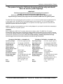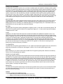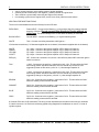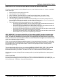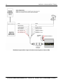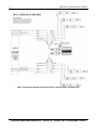
1
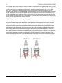
Installation Instructions
8 Channel Twin Fire Ignition System
PN 30-2820
4 Channel Twin Fire Ignition System
PN 30-2821
,!
WARNING:
This installation is not for the electrically challenged! Use this ignition
with EXTREME caution! If you are uncomfortable with anything about
this, please refer the installation to an AEM trained tuning shop or call
800-423-0046 for technical assistance. You should also visit the AEM
Performance Electronics Forum at http://forum.aempower.com
NOTE: AEM holds no responsibility for any engine damage that
results from the misuse of this product!
IMPORTANT:THE TWIN FIRE CDI MUST BE WIRED SO
EACH DISTINCT CHANNEL IS FIRING ONLY ONE COIL.
FIRING MORE THAN ONE COIL PER CHANNEL, PAIRING
OF INPUTS, OR PAIRING OF OUTPUTS WILL CAUSE
PERMANENT DAMAGE.
ADVANCED ENGINE MANAGEMENT INC.
th
2205 126 Street Unit A, Hawthorne, CA. 90250
Phone: (310) 484-2322 Fax: (310) 484-0152
http://www.aempower.com
Instruction Part Number: 10-2820 Rev F
© 2003-2006 Advanced Engine Management, Inc.
2
INSTALLATION INSTRUCTIONS
This product is legal in California for racing vehicles only and should
never be used on public highways.
IMPORTANT!
Read these instructions completely before attempting this installation!
You MUST ground all unused ignition trigger input wires!
Solid core spark plug wires cannot be used with an AEM Twin Fire ignition system!
Suppression type (resistor) spark plugs must be used with the AEM Twin Fire ignition system!
The AEM Twin Fire 8 Channel Ignition can be used on 3, 4, 5, 6, 8 and 10 cylinder engines equipped with four
or more ignition coils. The AEM Twin Fire 4 Channel Ignition can be used on 2, 4, 6 or 8 cylinder engines
equipped with up to 4 ignition coils. All AEM Twin Fire systems will accept trigger inputs from electronic DIS
type ignition systems as well as from igniters.
NOTE: It is strongly recommended that you have a wiring diagram for your specific vehicle before attempting to
install the AEM Twin Fire ignition system.
WARNING!
Before installing the AEM Twin Fire system, disconnect the battery cables. The AEM Twin Fire system
generates high voltage when power is supplied, this voltage is always present when the unit is on even if the engine
is not running. Improper handling may cause shock or death. The unit must be completely powered down when any
electrical work is performed on the vehicle. This is not a hollow warning, a modern CDI possesses enough
stored energy to cause serious harm to a person even after the key is turned off!
TECHNICAL FEATURES - 4 CHANNEL CDI
8-18 volts, negative ground
Operating Voltage:
7.0 Amps @ 10,000 RPM
Operating Current:
14,000 RPM, 4ch @ 14 volts
RPM Capability:
2, 3, 4 - rising or falling edge
Ignition Inputs:
4
Ignition Outputs:
Energy Storage Caps: 2
Ignition trigger
LED Indicator:
+12v square wave
Tach Output:
Multi-Strike Duration: ~20 degrees
175-189 milliJoules per spark
Energy Output Max:
Primary: 500-540 volts
Output Voltage:
Secondary (assume 100:1):
50,000 to 54,000 volts
5.5"L x 4.6"W x 1.4"H
Size:
1.7 Lbs
Weight:
TECHNICAL FEATURES - 8 CHANNEL CDI
8-18 volts, negative ground
Operating Voltage:
12.0 Amps @ 10,000 RPM
Operating Current:
14,000 RPM, 8ch @ 14 volts
RPM Capability:
5,6,7,8 - rising or falling edge
Ignition Inputs:
8
Ignition Outputs:
Energy Storage Caps: 2
Ignition trigger
LED Indicator:
+12v square wave
Tach Output:
Multi-Strike Duration: ~20 degrees
175-189 milliJoules per spark
Energy Output Max:
Primary: 500-540 volts
Output Voltage:
Secondary (assume 100:1):
50,000 to 54,000 volts
5.5"L x 4.6"W x 1.4"H
Size:
1.7 Lbs
Weight:
ADVANCED ENGINE MANAGEMENT INC. 2205 W. 126th STREET, UNIT A, HAWTHORNE, CA 90250
3
INSTALLATION INSTRUCTIONS
CAPACITIVE DISCHARGE
The AEM Twin Fire Ignition system is a 4 or 8 channel multiple-spark twin-capacitive discharge ignition system.
The Twin Fire ignition technology delivers full energy to the spark plug at engine speeds exceeding 10,000 rpm,
regardless of the time between ignition events, ensuring that pressurized fuel mixtures are thoroughly ignited.
The Twin Fire’s capacitive discharge ignition (CDI) produces a fast, high-energy pulse that is applied to the
ignition coil that is over 500 volts and up to 30 amps. A standard inductive ignition system typically produces
only about 250 volts on the coil primary. This higher voltage is what allows the coil to produce a much higher
spark voltage. A typical ignition coil (1:100 turns ratio) with an inductive ignition will produce about 25,000 volts
to the spark plug but using the CDI with the same coil will produce 50,000 volts or more at the spark plug.
MULTI-STRIKE
The AEM CDI Ignition system triggers multiple spark plug firings for each ignition event. The actual number of
sparks depends on the time available. This time will decrease as rpm increases and so does the number of
additional spark events. Generally, the additional sparks occur for approximately 20° of crankshaft rotation. At
high RPM there is only one spark due to the time limitations.
BATTERY
The AEM Twin Fire Ignition system is designed for negative ground, 12 volt and 16 volt electrical systems. The
AEM Twin Fire Ignition system will deliver full voltage with a supply of 8 - 18 volts and will operate with battery
voltages as low as 5 volts.
COILS
WARNING, THE AEM TWIN FIRE IGNITION CANNOT BE USED WITH MERCURY MARINE COILS! The
AEM Twin Fire Ignition system is designed to be used with most stock coils that do not have an integral igniter
(ignition amplifier). If your coil has only 2 electrical connections then it does not have an integral igniter. If it has
3 or more or is a DIS coil pack, it may have an igniter built in. If you have any questions concerning the
suitability of your coils with the AEM Twin Fire Ignition system, DO NOT hook up the AEM Twin Fire Ignition.
Contact the manufacturer of your car or a tuner knowledgeable with your application and confirm that the coils
do not have an internal ignitor. Hooking up the AEM Twin Fire Ignition to a coil with an internal ignitor will
destroy the coil as soon as the key is turned on.
TACHOMETERS
The AEM Twin Fire Ignition system features a 12 volt, square wave tachometer signal that can be used to drive
aftermarket tachometers, shift lights or data-loggers. It pulses 1 time for each ignition trigger signal.
WELDING
Before welding on your vehicle, disconnect the AEM Twin Fire Ignition system power cables from the battery.
Failure to do so may damage your ignition.
SPARK PLUGS AND WIRES
High quality resistor type spark plug and suppression wires are extremely important for the proper operation of
the AEM Twin Fire Ignition system. Solid core spark plug wires cannot be used with the AEM Twin Fire Ignition
system as they will cause excessive EMI which will interfere with the proper operation of the ignition system.
Attention should be paid to the routing of the spark plug wires. They should never be placed near sharp edges
or adjacent to each other in the firing order. Old, physically worn plug wires and boots should be discarded,
never reused. Any rub marks or pin-holes in the wire is a serious problem and will cause a misfire when the
ignition system is running at its highest energy.
MOUNTING
The AEM Twin Fire Ignition system may be mounted in any position as long as it is not in an enclosed location
nor near a large heat source. It may not be mounted directly to the engine nor should it be mounted near or
above the exhaust manifold(s).
WIRING
GENERAL WIRING RECOMMENDATIONS
• Solder wire joints for the most trouble-free connections.
• Always run wires away from direct heat and sharp edges.
ADVANCED ENGINE MANAGEMENT INC. 2205 W. 126th STREET, UNIT A, HAWTHORNE, CA 90250
4
INSTALLATION INSTRUCTIONS
•
•
•
•
A poor ground connection is the leading cause of ignition problems.
Connect ground wires directly to the negative (-) battery terminal or engine block.
There must be a ground strap connecting the engine to the chassis.
If connecting a ground to the engine block, ensure it is a clean, paint free metal surface.
AEM TWIN FIRE WIRE FUNCTIONS
There are 3 unterminated wires that exit directly from the CDI case:
RED HEAVY
Power INPUT - Connect to the Battery (+) or the positive side of the starter solenoid
through a 15A fuse. Do not connect this directly to 12volts without an
inline fuse. This should always have 12 volts when the battery is connected.
BLACK HEAVY
Ground INPUT - Connect to the Battery (-) or a good chassis ground.
WHITE
Tach - Connect to auxiliary tachometer, shift light etc…
I/O Harness connections (1 I/O harness supplied with the 4 channel, 2 harnesses supplied with the 8 channel)
WHITE
GREEN
YELLOW
VIOLET
Ign 1 input - Connect to the Ignition Amplifier or ECU Output of Channel 1.
Ign 2 input - Connect to the Ignition Amplifier or ECU Output of Channel 2.
Ign 3 input - Connect to the Ignition Amplifier or ECU Output of Channel 3.
Ign 4 input - Connect to the Ignition Amplifier or ECU Output of Channel 4.
RED (x2)
IGP - Connect to a switched +12v source. It should have power ONLY when the ignition
switch is turned on.
TAN
+ 540V - Connects to the positive (+) terminal on coils 1 & 3. This should be the ONLY
wire making contact with these terminals. This wire should only connect to coils
triggered by Brown or Blue wires ( coils 1 & 3 ). Uses storage capacitor #1
PINK
+ 540V - Connects to the positive (+) terminal on coils 2 & 4. This should be the ONLY
wire making contact with these terminals. This wire should only connect to to coils
triggered by Orange or Gray wires ( coils 2 & 4 ). Uses storage capacitor #2
BROWN
Coil 1 Out - Connects to the negative (-) terminal on Coil 1. This should be the ONLY
AEM wire making contact with this terminal.
ORANGE
Coil 2 Out - Connects to the negative (-) terminal on Coil 2. This should be the ONLY
AEM wire making contact with this terminal.
BLUE
Coil 3 Out - Connects to the negative (-) terminal on Coil 3. This should be the ONLY
AEM wire making contact with this terminal.
GRAY
Coil 4 Out - Connects to the negative (-) terminal on Coil 4. This should be the ONLY
AEM wire making contact with this terminal.
8 Channel CDI’s have 2 I/O Harnesses. The wiring on both harnesses are the same so the wiring for channels
5-8 are the same as 1-4. Refer to the following typical wiring diagrams for installations on most 4, 6, 8 and 10
cylinder engines.
ADVANCED ENGINE MANAGEMENT INC. 2205 W. 126th STREET, UNIT A, HAWTHORNE, CA 90250
5
INSTALLATION INSTRUCTIONS
WIRING INTO A FACTORY IGNITION SYSTEM WITH AN IGNITOR (IGNITION AMPLIFIER)
If you have a service manual or wiring diagram for your car, now is the time to refer to it. If one is not available,
follow these steps:
1.
2.
3.
4.
5.
6.
Disconnect all the wires leading to the coils.
Turn the ignition to the “ON” position.
Using a voltmeter, check each wire for 12 volts. Each coil should have 1 wire with 12 volts.
If none of the coils have 12 volts, have someone crank the engine while you test for 12 volts.
The wire that has 12 volts is the Coil positive (+).
Turn Off the ignition switch and connect the I/O Harness RED wire to the factory wiring and the I/O
Harness PINK or TAN wire to the positive (+) side of the coil. These two wires are not interchangeable,
they must go to their respective channels. Do this on each remaining coil.
7. The remaining wires on the factory wiring loom are the coil trigger wires.
o Connect the I/O Harness WHITE wire to the first factory trigger wire and then connect the I/O
Harness BROWN Coil (-) wire to the corresponding Coil terminal.
o Connect the I/O Harness GREEN wire to the second factory trigger wire and then connect the
I/O Harness ORANGE Coil (-) wire to the corresponding Coil terminal.
o Connect the I/O Harness YELLOW wire to the third factory trigger wire and then connect the I/O
Harness BLUE Coil (-) wire to the corresponding Coil terminal.
o Connect the I/O Harness VIOLET wire to the fourth factory trigger wire and then connect the I/O
Harness GRAY Coil (-) wire to the corresponding Coil terminal.
VERY IMPORTANT: If you are not using all the coil inputs then you MUST ground the unused trigger
input wires. The Tan coil +540v lead can out only power coils triggered by the Brown or Blue output
wires. The Pink coil +540v lead out can only power coils triggered by the Orange or Gray output wires.
Failure to follow these instructions WILL result in a misfire at idle and low engine load as well as erratic
spark events that may trigger randomly.
Check your wiring with the diagrams supplied on pages 6-13 and make changes if necessary. To confirm that
the wiring has been connected properly, plug in the supplied bypass plug (4 CH only) into the I/O Harness and
then start the engine. If the engine does not start or does not run properly then there is a wiring problem.
Recheck all of your wiring.
The only wires that should be going to your coils are the BROWN, ORANGE, BLUE, GREY, PINK and TAN
wires. Do not hook any other wires to the coil. The Red wires connect to a 12 volt battery source that
deactivates when the key is turned off. This turns the Twin Fire On and Off with the vehicles ignition switch.
Now it is safe to connect the large Red wire to battery positive (+) and the large Black wire to battery ground
negative.
WIRING DIAGRAMS
See the following wiring diagrams for installations on different vehicles and applications. If you experience
difficulties when installing your AEM Twin Fire system, call our Performance Electronics Help desk at (310) 4842322 x303 Monday - Friday, 8am - 5pm pacific standard time.
ADVANCED ENGINE MANAGEMENT INC. 2205 W. 126th STREET, UNIT A, HAWTHORNE, CA 90250
6
INSTALLATION INSTRUCTIONS
Typical 4 Cylinder COP (coil on plug) with an external ignitor (4 channel CDI)
ADVANCED ENGINE MANAGEMENT INC. 2205 W. 126th STREET, UNIT A, HAWTHORNE, CA 90250
7
INSTALLATION INSTRUCTIONS
Typical 4 Cylinder with 2 double ended coils and an external ignitor (4 channel CDI)
ADVANCED ENGINE MANAGEMENT INC. 2205 W. 126th STREET, UNIT A, HAWTHORNE, CA 90250
8
INSTALLATION INSTRUCTIONS
Typical 4 Cylinder with a coil pack and an external ignitor (4 channel CDI)
ADVANCED ENGINE MANAGEMENT INC. 2205 W. 126th STREET, UNIT A, HAWTHORNE, CA 90250
9
INSTALLATION INSTRUCTIONS
Typical 6 Cyl COP wired direct to an ECU without an external Ignitor (8 channel CDI)
ADVANCED ENGINE MANAGEMENT INC. 2205 W. 126th STREET, UNIT A, HAWTHORNE, CA 90250
10
INSTALLATION INSTRUCTIONS
8 Cylinder COP wired direct to an ECU without an external Ignitor (8 channel CDI)
ADVANCED ENGINE MANAGEMENT INC. 2205 W. 126th STREET, UNIT A, HAWTHORNE, CA 90250
11
INSTALLATION INSTRUCTIONS
8 Cylinder wasted spark without an external Ignitor (4 channel CDI)
ADVANCED ENGINE MANAGEMENT INC. 2205 W. 126th STREET, UNIT A, HAWTHORNE, CA 90250
12
INSTALLATION INSTRUCTIONS
10 Cylinder wasted spark without an external Ignitor (8 channel CDI)
ADVANCED ENGINE MANAGEMENT INC. 2205 W. 126th STREET, UNIT A, HAWTHORNE, CA 90250
13
INSTALLATION INSTRUCTIONS
Rotary engine with wasted spark lead, direct ignition trail with an external Ignitor (4 channel CDI)
ADVANCED ENGINE MANAGEMENT INC. 2205 W. 126th STREET, UNIT A, HAWTHORNE, CA 90250
14
INSTALLATION INSTRUCTIONS
Distributed engine with a single coil and an external Ignitor (4 channel CDI)
ADVANCED ENGINE MANAGEMENT INC. 2205 W. 126th STREET, UNIT A, HAWTHORNE, CA 90250
15
INSTALLATION INSTRUCTIONS
MK-IV Toyota Supra (wasted spark w/COP) and an external Ignitor (8 channel CDI)
ADVANCED ENGINE MANAGEMENT INC. 2205 W. 126th STREET, UNIT A, HAWTHORNE, CA 90250
16
INSTALLATION INSTRUCTIONS
Below is a list of the Twin Fire Ignition systems programmable features.
Switch 1
Multi-Strike Disable – S1 enables or disables multi-strike spark plug firings. Disabling Multistrike (S1 – On) makes engine timing much easier to check. Enabling Multi-strike (S1 – Off, Default) makes the
engine run smoother at low speeds.
Switch 2
Trigger Edge – S2 sets the input trigger edge that the Twin Fire uses to trigger the spark plug
firing. Rising edge (S2 - Off - Default) is used when the Twin Fire is wired in AFTER the ignitor (Ignition
Amplifier) or if the ignition did not have an external ignitor and there is not one inside the coils. Falling edge (S2
– On) is used when the Twin Fire is wired directly to the ECU and the Ignition trigger is a digital signal with high
signifying dwell time.
Switch 3
Wasted Spark – S3 programs the ignition for use on engines equipped with a single coil per
cylinder (720 firing S3 - On), or dual output coil feeding 2 cylinders (360 firing S3 - Off - Default).
PRESTART CHECK LIST
• The only wires that should be going to your coil (-) terminal are Brown, Orange, Blue and Grey.
• The only wires going to the coil positive (+) terminals are Pink or Tan.
• The only wires connected to the factory harness wires (inputs) are the White, Green, Yellow, Violet.
• The small Red wire of the Twin Fire is connected to a switched 12 volt source (factory harness).
• The AEM power leads are connected directly to the battery positive and negative terminals.
• The battery is connected and fully charged.
• The engine is equipped with a good ground strap to the chassis.
• CDI Switches properly set.
You can now remove the bypass plug and plug in the AEM Twin Fire Ignition system into the harness. Start the
engine to verify the engine timing is correct and that all functions are operating.
WARNING: The AEM Twin Fire system generates high voltage when power is supplied, this voltage is always
present when the unit is on even if the engine is not running. Improper handling may cause shock or even death.
This is NOT a hollow warning. Whenever the key is turned on, the primary coil (+) terminal is charged to 500+
volts! Do not touch the coil or connect test equipment to the terminals.
TROUBLESHOOTING
Every AEM Twin Fire Ignition system undergoes multiple quality checks including an 8 hour high power burn-in.
If you are having a problem with your Twin Fire, it is likely due to improper installation or wiring. Please refer to
the following while troubleshooting your installation before calling AEM’s Performance Electronics Help desk.
ENGINE MISFIRES
An engine misfire at higher rpm is not usually due to the ignition. Most of the time it is due to a coil or plug wire
problem allowing arcing to take place between the plug boot to ground:
• Check the positive and negative coil connections.
• Verify that all unused ignition trigger inputs are grounded.
• Ensure that the Tan coil +540v lead out only powers coils triggered by the Brown or Blue output wires.
• Ensure that the Pink coil +540v lead out only powers coils triggered by the Orange or Gray output wires.
• Check the condition of the plug wires with extra attention given to the ends. Check for a tight connection
and look for cuts, abrasions or obvious signs of burning.
• WARNING: There will be a very high voltage at the coil positive (+) terminal whenever the key is
turned on. Do not probe these terminals!
• WARNING: Do not touch the coil terminals during cranking or while the engine is running. A
severe shock will result.
CHECKING FOR SPARK
Use the following procedure to determine if the ignition is producing a spark.
1. Verify that the ignition switch is “Off”.
2. Set the “Trigger Edge – S2” switch to a rising edge trigger.
ADVANCED ENGINE MANAGEMENT INC. 2205 W. 126th STREET, UNIT A, HAWTHORNE, CA 90250
17
INSTALLATION INSTRUCTIONS
3. Remove the spark plugs and wires from the engine. With the plugs inserted in the end of the plug wires,
lay the spark plugs against a good ground.
4. Disconnect the trigger wire (White, Green, Yellow & Violet) from the factory harness.
5. Turn the ignition to the On position. Do not crank the engine.
6. Tap a trigger wire to a good ground. Each time you pull the wire from ground, a spark should jump cross
a spark plug. If a spark is present on all connected channels then the ignition is working properly.
7. If there is no spark:
A. Check all of the wiring.
B. Change coils, wires and spark plugs and repeat the test. If there is a spark now, one of those
components was at fault.
C. If there is still no spark, then verify that there is 12 volts on the small RED wire from the AEM
Twin Fire when the key is “On” or while the engine is cranking. If 12 volts is not present, then
you have to find a switched 12 volt source for this lead and do the test again.
D. If after following all of these troubleshooting procedures and verifying 100% of the wiring there
is still no spark, then the Ignition needs repair. See the AEM Twin Fire Warranty and component
Service section below for instructions.
FREQUENTLY ASKED IGNITION QUESTIONS
1. What’s the difference between a Twin Capacitive Discharge, regular Capacitive Discharge (CDI) and a
stock ignition system?
The majority of stock ignitions are inductive ignitions. CDI’s produce a fast, high-energy pulse that is applied to
the ignition coil that is over 500 volts and up to 30 amps. A standard inductive ignition system typically produces
250 volts on the coil primary. This higher voltage is what allows the coil to produce a much higher spark voltage.
A typical ignition coil (1:100 turns ratio) with an inductive ignition will produce about 25,000 volts to the spark
plug but using the AEM CDI with the same coil will produce 50,000 volts or more at the spark plug. A regular
CD ignition can produce full power sparks as long as the capacitor has time to recharge. Typically, this is more
than enough for most engines. However, if you attempt to trigger multiple sparks in quick succession, you will
reach it’s inherent time limitation. This is due to the fact that the typical CD ignition has a single storage
capacitor. While this cap is recharging or discharging, another full power spark is not possible. You must wait.
AEM’s patent pending multi-cap technology has been designed into the Twin Fire ignition system. It has 2
independent storage capacitors. They can charge, fire and recharge simultaneously. This means you can have
2 full power sparks in any relationship to each other, including at virtually the same time. This means more
ignition power at higher RPM on even fire engines, odd fire engines and even on twin plug combustion
chambers, allowing for leading and trailing ignition maps without limitation! This ability to generate full power
sparks regardless of engine RPM is why you will benefit with a Twin Fire ignition. With complete combustion
regardless of boost level, instantaneous throttle response, smoother idle, easier starts and reduced plug fouling
you can’t help but win. While all engines will realize this benefit, heavily modded engines will gain the most from
this type of ignition setup.
2. How do I know which wires come from each storage capacitor?
The +540v outputs from the 2 storage caps are the PINK and TAN wires. The TAN wire is for channels 1 & 3
and the PINK is for channels 2 & 4. These are not interchangeable. If these are hooked up wrong ( example:
PINK +540 to BROWN CH 1 trigger ) then misfires and extra sparks will occur. Do not do this!.
3. What is the best spark plug gap for my application?
Since there are so many engine combinations and manufacturers, AEM cannot recommend which gap is exactly
right for your application. Insufficient spark plug gap can cause pre-ignition, detonation, even engine damage.
Too much gap can result in a higher rate of misfires, noticeable loss of power, plug fouling, and poor economy.
When you raise the compression ratio or add forced induction (a turbo system, nitrous, or supercharger kit), you
must lower the gap (reduce gap about .004" for every 50 hp you add). However, when you add a high power
ignition system (such as the Spark1) you can open the gap back up about .002"-.005".
ADVANCED ENGINE MANAGEMENT INC. 2205 W. 126th STREET, UNIT A, HAWTHORNE, CA 90250
18
INSTALLATION INSTRUCTIONS
As an example, let's use a hypothetical `93 350 Chevrolet LT1 engine build-up...standard gap is .050" for an unmodified LT1. We'll add 150hp Nitrous, so we must lower the gap about .012" to .038". We then decide to add
the Spark1 and, using our guidelines as outlined above, we can now open the gap up .002"-.005" to about
.040"- .043".....following this basic guideline should get you very close. Further experimentation may be
necessary, but by starting with a larger gap than thought necessary to reduce the risk of detonation, you should
be safe. Other issues that may require a smaller gap are if the plug boot does not fit snug over the plug. If you
pull the plugs and see black streaks that will not wipe of where the plug boot sits then you have flashover. This
will also show up as misfires under high boost conditions. If you have this problem in addition to lowing the plug
gap you can use a silicon dielectric grease in the boot.
4. What heat range should I use for my spark plugs?
The heat range refers to how much heat a spark plug is capable of removing from the combustion chamber. When
compression is raised, along with the added power comes added heat. Since spark plugs must remove heat and a
modified engine makes more heat, the spark plug must remove more heat. A colder heat range spark plug must be
selected, and spark plug gaps should be adjusted smaller to ensure proper ignitability in this denser air/fuel mixture.
Selecting a spark plug with the proper heat range will ensure that the tip will maintain a temperature high enough to
prevent fouling, yet be cool enough to prevent pre-ignition. While there are many other things that can cause preignition, selecting the proper heat range spark plug will ensure that the spark plug itself is not a hot-spot source. As a
rule of thumb, every time you increase the compression ratio by one point, or for every 75-100 hp you add, go at least
one step colder. Remember, it is better to go colder than is thought necessary. The worst that can happen in this
scenario is that the plugs will foul out. If you inadvertently select a heat range that is too hot, the resulting pre-ignition
and detonation can cause serious engine damage.
ADVANCED ENGINE MANAGEMENT INC. 2205 W. 126th STREET, UNIT A, HAWTHORNE, CA 90250
19
INSTALLATION INSTRUCTIONS
AEM Electronics Warranty
Advanced Engine Management Inc. warrants to the consumer that all AEM Electronics
products will be free from defects in material and workmanship for a period of twelve months
from date of the original purchase. Products that fail within this 12-month warranty period will
be repaired or replaced when determined by AEM that the product failed due to defects in
material or workmanship. This warranty is limited to the repair or replacement of the AEM
part. In no event shall this warranty exceed the original purchase price of the AEM part nor
shall AEM be responsible for special, incidental or consequential damages or cost incurred
due to the failure of this product. Warranty claims to AEM must be transportation prepaid and
accompanied with dated proof of purchase. This warranty applies only to the original
purchaser of product and is non-transferable. All implied warranties shall be limited in
duration to the said 12-month warranty period. Improper use or installation, accident, abuse,
unauthorized repairs or alterations voids this warranty. AEM disclaims any liability for
consequential damages due to breach of any written or implied warranty on all products
manufactured by AEM. Warranty returns will only be accepted by AEM when accompanied
by a valid Return Merchandise Authorization (RMA) number. Product must be received by
AEM within 30 days of the date the RMA is issued.
Please note that before AEM can issue an RMA for any electronic product, it is first
necessary for the installer or end user to contact the tech line at 1-800-423-0046 to discuss
the problem. Most issues can be resolved over the phone. Under no circumstances should a
system be returned or a RMA requested before the above process transpires.
AEM will not be responsible for electronic products that are installed incorrectly, installed in a
non approved application, misused, or tampered with.
Any AEM electronics product can be returned for repair if it is out of the warranty period.
There is a minimum charge of $50.00 for inspection and diagnosis of AEM electronic parts.
Parts used in the repair of AEM electronic components will be extra. AEM will provide an
estimate of repairs and receive written or electronic authorization before repairs are made to
the product.
ADVANCED ENGINE MANAGEMENT INC. 2205 W. 126th STREET, UNIT A, HAWTHORNE, CA 90250