1
5
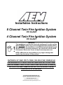
INSTALLATION INSTRUCTIONS
WIRING INTO A FACTORY IGNITION SYSTEM WITH AN IGNITOR (IGNITION AMPLIFIER)
If you have a service manual or wiring diagram for your car, now is the time to refer to it. If one is not available,
follow these steps:
1.
2.
3.
4.
5.
6.
Disconnect all the wires leading to the coils.
Turn the ignition to the “ON” position.
Using a voltmeter, check each wire for 12 volts. Each coil should have 1 wire with 12 volts.
If none of the coils have 12 volts, have someone crank the engine while you test for 12 volts.
The wire that has 12 volts is the Coil positive (+).
Turn Off the ignition switch and connect the I/O Harness RED wire to the factory wiring and the I/O
Harness PINK or TAN wire to the positive (+) side of the coil. These two wires are not interchangeable,
they must go to their respective channels. Do this on each remaining coil.
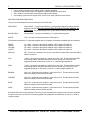
7. The remaining wires on the factory wiring loom are the coil trigger wires.
o Connect the I/O Harness WHITE wire to the first factory trigger wire and then connect the I/O
Harness BROWN Coil (-) wire to the corresponding Coil terminal.
o Connect the I/O Harness GREEN wire to the second factory trigger wire and then connect the
I/O Harness ORANGE Coil (-) wire to the corresponding Coil terminal.
o Connect the I/O Harness YELLOW wire to the third factory trigger wire and then connect the I/O
Harness BLUE Coil (-) wire to the corresponding Coil terminal.
o Connect the I/O Harness VIOLET wire to the fourth factory trigger wire and then connect the I/O
Harness GRAY Coil (-) wire to the corresponding Coil terminal.
VERY IMPORTANT: If you are not using all the coil inputs then you MUST ground the unused trigger
input wires. The Tan coil +540v lead can out only power coils triggered by the Brown or Blue output
wires. The Pink coil +540v lead out can only power coils triggered by the Orange or Gray output wires.
Failure to follow these instructions WILL result in a misfire at idle and low engine load as well as erratic
spark events that may trigger randomly.
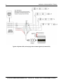
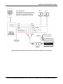
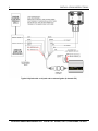
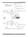
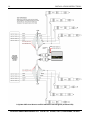
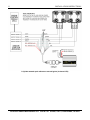
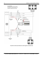
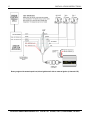
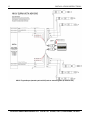
Check your wiring with the diagrams supplied on pages 6-13 and make changes if necessary. To confirm that
the wiring has been connected properly, plug in the supplied bypass plug (4 CH only) into the I/O Harness and
then start the engine. If the engine does not start or does not run properly then there is a wiring problem.
Recheck all of your wiring.
The only wires that should be going to your coils are the BROWN, ORANGE, BLUE, GREY, PINK and TAN
wires. Do not hook any other wires to the coil. The Red wires connect to a 12 volt battery source that
deactivates when the key is turned off. This turns the Twin Fire On and Off with the vehicles ignition switch.
Now it is safe to connect the large Red wire to battery positive (+) and the large Black wire to battery ground
negative.
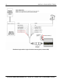
WIRING DIAGRAMS
See the following wiring diagrams for installations on different vehicles and applications. If you experience
difficulties when installing your AEM Twin Fire system, call our Performance Electronics Help desk at (310) 4842322 x303 Monday - Friday, 8am - 5pm pacific standard time.
ADVANCED ENGINE MANAGEMENT INC. 2205 W. 126th STREET, UNIT A, HAWTHORNE, CA 90250