1
Generator set status and control
Trending
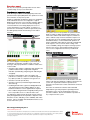
The genset status summary provides an analog and
graphical display of critical generator set operating
parameters for each generator set in the system. The
screen includes generator set state display (stopped, time
delay start, idle speed state, rated volts/hertz,
synchronizing, load share or load govern); analog AC
metering for generator set (3-phase, AC volts and current,
frequency, kW and power factor); and three-phase AC
bus voltage and frequency. The screen provides a
complete display of engine and alternator data present in
the generator set control. The screen also shows status of
the generator set breaker. Hot buttons are provided for
this data on all generator sets in the system, including
system equipment provided by third parties.
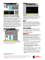
The touchscreen provides real-time trend charts for AC
output parameters and continuously monitors average
voltage, frequency, total kilowatts, and average
amperage. Scales of values displayed are fieldconfigurable.
Generator set manual control
Alarms
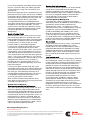
Any alarm on any generator set or in the system will
cause an alarm bar and warning condition display to
appear on the touchscreen. A click on the bar displays a
pop-up screen describing the equipment where the fault
has occurred, and the name of the fault. The screen
allows the operator to attempt to reset warning
conditions from the HMI.
Service information
System information and service information, including
the name, address and phone number for the local
service point for the equipment, is provided on the main
menu screen for the system.
Internal components
System PLC
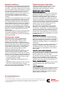
Manual control of the generator set paralleling function
and resetting of warning condition faults is available to
users via a password-protected access.
Paralleling control functions (synchronizing, load sharing,
etc.) are provided by the PowerCommand Generator
set paralleling controls. System control logic such
as load add and shed sequence is performed by a
programmable logic controller (PLC). The PLC is a rackmounted system of components with swappable cards
to allow easy servicing of components. Other features of
the PLC include:
• On-line changes. The PLC may be interconnected to a
personal computer and control sequences may be
modified without shutting down the system.
• EEPROM program storage. The PLC program is
stored in non-volatile EEPROM memory with
additional battery backup of the PLC RAM for storing
system configuration settings.
• LED status indicators. The PLC and input/output (I/O)
blocks include LED status indicators for use in viewing
system status and diagnosis of failures.
• I/O block surge suppressors. Inputs and outputs to
the PLC are connected via integral surge suppressors
to provide reliable protection against over-voltage
damage.
Our energy working for you.™
www.cumminspower.com
©2009 Cummins Power Generation Inc. All rights reserved. Cummins Power Generation and Cummins are registered trademarks of Cummins
Inc. PowerCommand, InPower and “Our energy working for you.” are trademarks of Cummins Power Generation. Other company, product,
or service names may be trademarks or service marks of others. Specifications are subject to change without notice.
S-1611 (9/09) Page 3 of 7