1
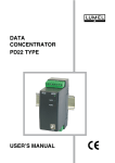
MODULE
WITH 8 LOGIC
INPUTS
SM5 TYPE
USER’S MANUAL
1
2
CONTENTS
1. APPLICATION..................................................................................5
2. MODULE SET ..................................................................................5
3. BASIC REQUIREMENTS AND OPERATIONAL SAFETY..............6
4. INSTALLATION ................................................................................8
4.1. Module fixing ............................................................................8
4.2. Electrical connections...............................................................8
5. SERVICE ........................................................................................ 11
5.1 Description of the MODBUS protocol implementation ........... 11
5.2 Description of the MODBUS protocol functions .....................12
5.3. Map of module registers .........................................................15
5.4. Set of module registers ..........................................................16
6. TECHNICAL DATA ........................................................................20
7. BEFORE A DAMAGE WILL BE DECLARED ...............................21
8. ORDERING CODES ......................................................................22
9. MAINTENANCE AND GUARANTEE ............................................23
3
4
1. APPLICATION
The SM5 module has 8 logic inputs and RS-485 and RS-232 interfaces with
MODBUS RTU and ASCII transmission protocols.
It is destined to readout logic states of logic inputs and enables their access in
industrial systems. Ports in RS-485 and RS-232 are galvanically isolated from
input signals and the supply. The module programming is possible by means of the
RS-485 or the RS-232 port. Configurable baud rate: 2400, 4800, 9600, 19200,
34800, 57600, 115200 bit/s. The SM5 module set includes a connecting cable to
connect with the PC computer (RS-232).
2. MODULE SET
The set consists of:
- SM5 module ................................................................... 1 pc.
- user’s manual ................................................................. 1 pc.
- guarantee card ............................................................... 1 pc.
- plug with BU1005 screw terminals ................................. 2 pcs
- plug with BU0204 screw terminals ................................. 2 pcs
- RS-232 socket hole plug ................................................ 1 pc
- RS-232 wire to connect with the computer (1.5 m.) ....... 1 pc
When unpacking the module, please check whether the type and version code
on the data plate correspond to the order.
5
3. BASIC REQUIREMENTS, SAFETY INFORMATION
Symbols located in this service manual mean:
WARNING!
Warning of potential, hazardous situations. Especially important, one
must acquaint with this before connecting the module. The non-observance of notices marked by these symbols can occasion severe injuries
of the personnel and the damage of the module.
CAUTION!
Designates a general useful note. If you observe it, handling of the
module is made easier. One must take note of this, when the module
is working inconsistently to the expectations. Possible consequences
if disregarded !
In the security scope the module the requirements of the EEC. Low-Voltage Directive
(EN 61010 -1 issued by CENELEC).
Remarks concerning the operator safety:
1. General
l The SM5 module is destined to be installed in measuring systems,
on a 35 mm mounting rail
l Non-authorized removal of the required housing, inappropriate use, incorrect
installation or operation creates the risk of injury to personnel or damage to
equipment. For more detailed information please study the user’s manual.
l All operations concerning transport, installation, and commissioning as well
as maintenance must be carried out by qualified, skilled personnel and
national regulations for the prevention of accidents must be observed.
l According to this basic safety information, qualified, skilled personnel are
persons who are familiar with the installation, assembly, commissioning, and
operation of the product and who have qualifications necessary for their
occupation.
2. Transport, storage
Please observe the notes on transport, storage and appropriate handling.
Observe the climatic conditions given in technical data.
3. Installation
l The module must be installed according to the regulation and instructions
given in this user’s manual.
l Ensure proper handling and avoid mechanical stress.
l Do not bend any components and do not change any insulation distances.
6
l Do not touch any electronic components and contacts.
l Modules may contain electrostatically sensitive components, which can
easily be damaged by inappropriate handling.
l Do not damage or destroy any electrical components since this might
endanger your health!
4. Electrical connection
l Before switching the module on, one must check the correctness of
connection to the network.
l In case of the protection terminal connection with a separate lead, one must
remember to connect it before the connection of the module to the mains.
l When working on live modules, the applicable national regulations for the
prevention of accidents must be observed.
l The electrical installation must be carried out according to the appropriate
regulations (cable cross-sections, fuses, PE connection). Additional
information can be obtained from the user’s manual.
l The documentation contains information about installation in compliance with
EMC (shielding, grounding, filters and cables). These notes must be observed
for all CE-marked products.
l The manufacturer of the measuring system or installed devices is responsible
for the compliance with the required limit values demanded by the EMC
legislation.
5. Operation
l Measuring systems including SM5 modules must be equipped with protection
devices according to the corresponding standard and regulations for
prevention of accidents.
l After the instrument has been disconnected from the supply voltage, live
components and power connections must not be touched immediately
because capacitors can be charged.
l The housing must be closed during operation.
l The RS-232 socket serves only to connect the device (Fig. 2) working with
the MODBUS protocol. When the module is not used, place the hole plug in
the RS-232 socket of the module.
6. Maintenance and servicing
Please observe the manufacturer’s documentation.
Read all product-specific safety and application notes in this user’s manual.
l Before taking the module out, one must turn the supply off.
l The removal of the module housing during the guarantee period may cause
its cancellation.
7
4. INSTALLATION
4.1 Module fixing
The SM5 module is fixed on a 35 mm rail in accordance with EN 60715. The module
housing is made of a self-extinguishing plastic. Overall dimensions of the housing:
45 x 120 x 98 mm.
Overall dimensions and the fixing way are presented on the fig. 1.
Fig.1. Overall dimensions and way of the module fixing
4.2. Electrical connections
Following external wires can be connected to the module:
- up to 2.5 mm 2 cross-section (from supply and interface side),
- up to 1.5 mm 2 cross-section (from input signal side).
Caution:
One must pay special attention to the correct connection of external signals (see fig. 2)
8
Caution:
Regarding electromagnetic interference one must use shielded wires to
connect binary input signals and RS-485 interface signals. The shield must
be connected to the protective terminal in one point.
Fig 2. Electrical connections of SM5 logic input module
There are three diodes on the frontal plate:
l green
- signals switching the supply on
l green (RxD) - signals data reception through the module
l yellow (TxD) - signals data transmission through the module
9
The „+” signal (terminal 10) is the 5 V output with admissible overload 100 A. One
must connect binary signals to the mass and appropriate output terminal.
The way to connect interfaces are shown on fig. 3 and 4. To obtain a correct transmission through the RS-485 interface it is necessany to connect lines A and B lines
in parallel with their equivalents in other devices. The connection must be made
with a shielded wire. The shield must be connected to a shielded wire. The shield
must be connected to the protective terminal, in one point.
The GND line serves to equalize potentials of interface lines in the communicating
devices.
To obtain the communication with the computer of PC class throught the RS-485
port, it is essential to apply an RS-232/RS-485 converter (e.g. PD51 from Lumel
production) or an RS-485 interface card. Marking of transmission lines for the card
in the PC computer depends on the card producer.
To obtain the connection through the RS-232 port, the added wire in the module
set, is sufficent.
The module can be connected to a device of master type through one interface
port. In case of the simultaneous connection of both ports, the module will work
through the RS-232 interface
Fig. 3 Way of the RS-485 interface connection.
10
Fig. 4 Way of the RS-232 interface connection.
5. SERVICE
After connecting external signals and switching the supply on, the SM5 module is
ready to work.
The lighted green diode signals the module work. The green diode (RxD) signals
the module polling, however the yellow diode (TxD) signals the module response.
Diodes should ignite in cycles during the data transmission, through the RS-232 or
the RS-485 interface. Programmable parameters of the module can be programmed
by means of RS-232 or RS-485 ports.
The RS-232 port has constant transmission parameters acc. to technical data, what
enables the connection to the module even when programmed parameters of the
digital RS-485 output (address, mode, rate) are unknown
The RS-485 standard allows to the direct connection to 32 devices on a single serial
link up to 1200 m. To connect a greater number of devices it is necessary to use
additional intermediate-separating systems (e.g. the PD51 converter/repeater).
5.1. Description of MODBUS protocol implementation
The transmission protocol describes ways of the information exchange between
devices through serial links.
The MODBUS protocol has been implemented in the module in accordance with
the PI-MBUS-300 Rev G specification of the Modicon company.
Set of parameters of the module serial link in the MODBUS protocol:
l module address
- 1... 247
l baud rate
- 2400, 4800, 9600, 19200, 38400, 57600, 115200 bit/s
l working modes
- ASCII, RTU
11
l
information unit
l
maximal response time
- ASCII: 8N1, 7E1, 7O1
- RTU: 8N2, 8E1, 8O1, 8N1
- 300 ms.
The parameter configuration of the serial link is described in the further part of the
user’s manual. It consists on establishing the baud rate (baud parameter), device
address (Adr parameter) and the information unit type (Mode parameter).
In case of the module connection with the computer through the RS-232 wire, the
module set automatically following transmission parameters:
Baud rate:
9600 bps,
Working mode:
RTU 8N1,
Address:
1.
Notice: Each module connected to the communication network must:
l have a unique address, different from addresses of other devices
connected to the network,
l identical baud rate and information unit type,
l the message sent with the address „0” is identified as the data
transmission mode (transmission to many devices).
5.2. Description of the MODBUS protocol function
Following functions of the MODBUS protocol have been implemented in the SM5
module.
Description of MODBUS protocol functions
Table 2
Code
Signification
02 (02h)
03 (03h)
Readout of n-bit registers
Readout of n-register
04 (04h)
06 (06h)
16 (10h)
17 (11h)
Write of n-input registers
Write of a single register
Write of n-registers
Slave device identification
Readout of n-registers (code 02h)
The function is not accessible in the broadcast mode.
Example: Readout of 8 bit registers beginning by the register with the
07D0h (2000) address
Request:
Register address
Device
address
Function
01
02
12
Number of registers
Hi
Lo
Hi
Lo
Checksum
CRC
07
D0
00
08
7941
Answer:
Device
address
Function
Number
of bytes
Value from the register
2200 - 2207
Checksum
CRC
01
02
01
01
6048
Readout of n-registers (code 03h)
The function is not accessible in the broadcast mode.
Example: Readout of 2 registers with 1DBDh (7613) address:
Request:
Device
address
Function
01
03
Register
address
Hi
1D
Register
address
Lo
BD
Number of
registers
Hi
00
Number of
registers
Lo
02
Checksum
CRC
52 43
Answer:
Device
address
Function
Number
of bites
01
03
08
Value from the register
1DBD (7613)
3F
80
00
Value from the register
1DBE (7614)
00
40
00
00
00
Checksum
CRC
42 8B
Readout of n-input registers (code 04h)
The function is not accessible in the broadcast mode.
Example: readout of 1 register with the 0FA3h (4003) address
Request:
Device
address
Function
01
04
Register
address
Hi
0F
Register
address
Lo
A3
Number of
registers
Hi
00
Number of
registers
Lo
01
Checksum
CRC
C2 FC
Answer:
Device
address
Function
Number
of bytes
01
04
02
Value from the register
0FA3 (4003)
00
01
Checksum
CRC
78 F0
13
Write of values in the register (code 06h)
The function is accessible in broadcast mode.
Example: Write of the register with 1DBDh (7613) address
Request:
Device
address
Function
01
06
Register
address
Hi
1D
Register
address
Lo
BD
Register
address
Hi
1D
Register
address
Lo
BD
Checksum
CRC
Value from the register
1DBD (7613)
3F
80
00
00
85 AD
Answer:
Device
address
Function
01
06
Checksum
CRC
Value from the register
1DBD (7613)
3F
80
00
85 AD
00
Write into n-registers (code 10h)
The function is accessible in the data transmission mode.
Example: Write 2 registers beginning from the register with 1DBDh (7613) address.
Device
address
Function
Request:
01
10
Register
address
Lo
Hi
1D BD
Number of
registers
Hi
Lo
00
02
Number
of bytes
08
Value from the register
1DBD (7613)
Value from the
register
1DBE (7614)
3F 80 00 00 40 00 00 00
Checksum
CRC
03 09
Answer:
Device
address
Function
Register
address
Hi
Register
address
Lo
01
10
1D
BD
Number of Number of Checksum
registers
registers
(CRC)
Lo
Hi
00
02
D7 80
Report identifying the device (code 11h)
Request:
Device
address
Function
01
11
Checksum
(CRC)
C0 2C
Answer:
Device
address
Function
Number of
bytes
Device identifier
Device
state
Software version
number
01
11
06
8D
FF
XXXX
14
Checksum
Device address
- depends on the set value,
Function
- function number: 0x11,
Number of bytes
- 0x08
Device identifier
- 0x8F
Device state
- 0xFF
No of the software version - software version implemented in the module:1.00
software
XXXX - 4-byte variable of float type
Checsum
- 2 bytes, in case of work in the RTU mode
- 1 byte, in case of work in the ASCII mode
Example:
The work in RTU mode, e.g.: Mode = RTU 8N2 (value 0x02 in case of
readout/write through the interface).
Device address set on Adr=0x01,
For the SM5 module, the response frame has the following shape:
Device
address
Function
Number
of bytes
Device
identifier
Device
state
Nunber of
softwer wersion
Checksum
CRC
01
11
06
8E
FF
3F 80 00 00
AE 1B
Jest to moduł SM5, wersja oprogramowania 1.00
5.3. Register map of the module
Register map of SM5 module series
Table 2
Address
range
Value type
Description
2000-2007
bool (1 bit)
The value is located in 1-bit register. Registers can be read
out and written.
4000-4100
integer
(16 bitów)
The value is located in 16-bit registers. The register content
corresponds to the 32-bit register contents from the 7500
area. Registers are only for readout.
4200-4300
integer
(16 bitów)
The value is located in 16-bit registers. The register content
corresponds to the 32-bit register contents from the 7600
area. Registers can be read out and written.
7500-7600
float (32 bity)
The value is located in the 2-bit register. Registers are only
for readout.
7600-7700
float (32 bity)
The value is located in the 32-bit register. Registers can be
read out and written.
15
5.4. Set of module registers
4000
7500
Identifier
Unit
The value is placed in 32-bytes
registers.
Name
Table 3
Write (w)/Readout (r)
The value is placed in 16-bytes registers. These registers
content corresponds to the
content of 32-bit registers from
the area 7500.
The value is placed in 1-bytes
registers. These registers content corresponds to the content
of 32-bit registers from the
area 7500.
Set of registers for readout the SM5 module
o
–
Constant identifying the device
Quantity name
4001
7501
Status 1
o
–
Status 1 is a register describing
current states of binary inputs.
4002
7502
Status 2
o
–
Status 2is a register describing
current transmission parameters.
2000
4003
7503
W1
o
–
Value of read out state of input 1
2001
4004
7504
W2
o
–
Value of read out state of input 2
2002
4005
7505
W3
o
–
Value of read out state of input 3
2003
4006
7506
W4
o
–
Value of read out state of input 4
2004
4007
7507
W5
o
–
Value of read out state of input 5
2005
4008
7508
W6
o
–
Value of read out state of input 6
2006
4009
7509
W7
o
–
Value of read out state of input 7
2007
4010
7510
W8
o
–
Value of read out state of input 8
State IN8
State IN7
State IN6
State IN5
State IN4
State IN3
State IN2
State IN1
Description of the Status1 register
X
X
X
X
X
X
X
X
X
X
X
X
X
X
X
X
bits 15
14
13
12
11
10
9
8
7
6
5
4
3
2
1
MSB
16
0
LSB
Bit-15...8 not used
State 0
Bit- 0 State of IN 1 input
0 - open
1 - shorting
Bit- 1 State of IN 2 input
0 - open
1 - shorting
Bit- 2 State of IN 3 input
0 - open
1 - shorting
Bit- 3 State of IN 4 input
0 - open
1 - shorting
Bit- 4 State of IN 5 input
0 - open
1 - shorting
Bit- 5 State of IN 6 input
0 - open
1 - shorting
Bit- 6 State of IN 7 input
0 - open
1 - shorting
Bit- 7 State of IN 8 input
0 - open
1 - shorting
17
Description of the Status 2 register
Operating
mode and information unit
Baud rate
X
X
X
X
X
X
X
X
X
X
X
X
X
X
X
bits 15
14
13
12
11
10
9
8
7
6
5
4
3
2
1
MSB
0
LSB
Bit-15...6 Not used
Their States are free
Bit-5...3 Operating mode and information unit
000 - interface switched off
001 - 8N1 - ASCII
010 - 7E1 - ASCII
011 - 7O1 - ASCII
100 - 8N2 - RTU
101 - 8E1 - RTU
110 - 8O1 - RTU
111 - 8N1 - RTU
Bit-2...0 Baud rate
000 - 2400 bit/s
001 - 4800 bit/s
010 - 9600 bit/s
011 - 19200 bit/s
100 - 38400 bit/s
101 - 57600 bit/s
110 - 115200 bit/s
18
X
4200
7600
Identifier
r
8D
Device identifier
4201
7601
Rate
w/r
0... 6
Baud rate of the RS-485
interface (bit/s)
Symbol
Write (w)/Readout (r)
The value is placed in 32-bit
registers.
Table 4
The value is placed in 16-bytes registers. These registers
content corresponds to the
content of 32-bit registers
from the area 7600.
Set of registers for SM5 module readout and write
Range
Description
Value
0
1
2
3
4
5
6
4202
7602
Mode
w/r
0... 7
2400
4800
9600
19200
38400
57600
115200
Kind of transmission via the RS-485
interface
Value
0
1
2
3
4
5
6
7
Interface switched off
ASCII 8N1
ASCII 7E1
ASCII 7O1
RTU 8N2
RTU 8E1
RTU 8O1
RTU 8N1
4203
7603
Address
w/r
1... 247
Device address
4204
7604
Apply
w/r
0... 1
Register confirming changes
of transmission parameters
19
6. TECHNICAL DATA
Logic levels
Transmission data:
a) RS-485 interface:
- transmission protocol
- ASCII:
- RTU:
- baud rate:
- address:
b) RS-232 interface:
- transmission protocol
- RTU:
- baud rate:
- address:
1 logic: shorted input
0 logic: open input
shorting resistance of the contact without
potential ³ 10 kW
opening resistance of the contact without
potential ³ 150 kW
MODBUS
8N1, 7E1, 7O1
8N2, 8E1, 8O1, 8N1
2400, 4800, 9600, 19200,
38400, 57600, 115200 bit/s
1... 247
MODBUS
8N1
9600 bit/s
1
Power consumption by the module £ 1.5 VA
Rated operation conditions:
- supply voltage
10...24...50 V a.c./d.c.
or 85...230...253 V a.c./d.c.
- Supply voltage frequency
40...50/60...440 Hz
- ambient temperature
-20...23...55°C
- relative humidity
< 95% (inadmissible condensation)
- external magnetic field
< 400 A/m
- work position
any
Storage and transport conditions:
- ambient temperature
- relative humidity
- 20... 70°C
< 95% (inadmissible condensation)
Ensured protection grade:
- from the housing
- from terminal side
IP 40
IP 20
20
Dimensions
45 x 120 x 100 mm
Weight
< 0.25 kg
SM5 housing
adapted to be mounted on a 35 mm rail
acc. to EN 60715
Electromagnetic compatibility:
- Immunity
- emission
acc. to EN 61000-6-2
acc. to EN 61000-6-4
Safety requirements acc.to EN 61010-1:
- installation category
III
- pollution grade
2
maximal phase-to-earth work voltage:
- for the supply circuit
300 V
- for other circuits
50 V
7. BEFORE A FAILURE WILL BE DECLARED
In case of incorrect symptoms please to acquaint with the table below.
SYMPTOMS
PROCEDURE
1. The green diode
is off.
Check the connection of the network cable
2. The module does not
communicate with
the device master via
the RS-232 port.
Lack of transmission
signalling on RxD
and TxD diodes.
Check if the wire is connected to the appropriate
module socket.
Check if the device master is set on 9600 baud
rate, 8N1 mode and address 1.
3. The module does not
communicate with
the device master
via the RS-485 port.
Lack of transmission
signalling on RxD
and TxD diodes.
Check if the wire is connected to the appropriate
module terminal. Check if the device master is set
on the same transmission parameters as the module (baud rate, mode, address). In case of necessity
to change transmission parameters when we cannot communicate through RS-485 one can use the
RS-232 port which has constant transmission
parameters (in case of further problems, see the
section 2). After changing e RS-485 parameters
into the required one, one can switch over on
RS-485 port.
REMARKS
(RS-232 has
constant transmission parameters)
21
8. ORDERING CODES
Table 5
Module of 8 binary inputs - SM5
X
XX
X
Supply voltage:
85...230...253 V a.c./d.c....................................................... 1
20...24...50 V a.c./d.c........................................................... 2
on order * ............................................................................. X
Kind of version:
catalogue ....................................................................................00
custom -made * ......................................................................... XX
Acceptance tests:
without extra requirements .................................................................8
with an extra quality inspection certificate ..........................................7
other requirements agreed with the manufacturer* ............................X
* code numbering is settled by the manufacturer.
Example of order
SM5 1 00 7 code means:
SM5
1
00
7
22
- Module of 8 binary inputs
- supply: 85...230...253 V a.c/d.c.
- catalogue version
- with an extra quality inspection certificate
9. MAINTENANCE AND GUARANTEE
The SM5 module does not require any periodical maintenance.
In case of some incorrect operations:
1. After the dispatch date and within the period stated in the guarantee card
One should return the instrument to the Manufacturer’s Quality Inspection Dept. If
the module has been used in compliance with the instructions, the Manufacturer
guarantees to repair it free of charge. The disassembling of the housing causes
the cancellation of the granted guarantee.
2. After the guarantee period:
One should send the instrument to repair it in an authorised service workshop.
Spare parts are available for the period of five years from the date of purchase.
Our policy is one of continuous improvement and we reserve the
right to make changes in design and specifications of any products
as engineering advances or necessity requires and revise the above
specifications without notice.
23
24
25
26
27
SM5-07.C