1
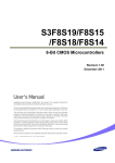
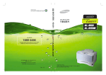
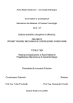
DH-300 Service Manuai
DH-300
SERVICE MANUAL
DH-300 Service Manuai
Table of Contents
Points for Attention
Warning
Caution
ClassI
Please disconnect the unit under these conditions
Important Safety Instructions
Software Upgrade
Circuit Diagram , component layout and exploded view
MPEG IC Block Diagram
Power board Circuit Diagram
MPEG board Circuit Diagram
Front Panel board Circuit Diagram
Exploded view
Symptom and Solution
Parts List
Power board Parts List
MPEG board Parts List
Front Panel board Parts List
DH-300 Service Manuai
1.Points for Attention
WARNING:
To reduce the risk of fire or electric shock, do not expose this appliance to rain or moisture.
The apparatus shall not be exposed to dripping or splashing and that no objects filled with liquid,
such as vases, shall be placed on the apparatus.
CAUTION
RISK OF ELECTRIC SHOCK
DO NOT OPEN
CLASS 1
LASER PRODUCT
The lightning flash with arrowhead symbol, within an equilateral triangle, is
intended to alert the user to the presence of uninsulated “dangerous voltage”
within the product’s enclosure that may be of sufficient magnitude to constitute
a risk of electric shock to persons.
The exclamation point within an equilateral triangle is intended to alert the user
to the presence of important operating and maintenance (servicing) instructions
in the literature accompanying the appliance.
CAUTION:
To reduce the risk of fire and electrical shock, do not remove the cover of this unit. Please refer all
servicing difficulties to qualified technicians .
Use of controls or adjustments or performance of procedures other than those specified may result
in hazardous radiation exposure.
Where the MAINS plug or an appliance coupler is used as the disconnect device, the disconnect
device shall remain readily operable.
CLASSI:
LASER PRODUCT - This marking indicates the presence of laser beams used in this unit, and CLASS
I refers to laser beams of the weaker class. There is no danger of hazardous radiation outside this
unit.
Double insulation
This is class II apparatus
Please disconnect the unit under these conditions:
Do not overload wall outlets, extension cords or convenience receptacles beyond their capacity,
since this can result in fire or electric shock.
Do not use suitable outlet, it might be dangerous.
Check the connection regularly. If any rupture or failure in insulation, call for a maintenance man
to replace them.
To ensure reliable operation, and to protect it from overheating, the unit must be put in somewhere
well ventilated.
Do not use power-line operated sets near water *for example, near a bathtub, washbowl, kitchen
sink, or laundry tub, in a wet basement, or near a swimming pool, etc.
Do not place the unit on an unstable object. The set may fall, causing serious injury to a child or
an adult, and serious damage to the unit.
Never let any liquid spattered on the unit. It might cause electric shock or fire hazard.
Never place the unit near or over such objects: for example, radiator, heat register, stove or other
heat sources. (including amplifier)
Unplug the unit from the wall outlet before cleaning or polishing it. Do not use liquid cleaners or
aerosol cleaners. Use a cloth lightly dampened with water for cleaning the exterior of the unit.
Never place heavy object on the unit.
DH-300 Service Manuai
Important Safety Instructions:
Read these instructions.
Keep these instructions.
Heed all warning.
Follow all instructions.
Do not use this apparatus near water.
Clean only with dry cloth.
Do not block any ventilation openings, Install in accordance with the manufacturer’s instructions.
Do not install near any heat sources such as radiators, heat registers, stoves, or other apparatus
(including amplifiers) that produce heat.
Do not defeat the safety purpose of the polarized or grounding-type plug. A polarized plug has
two blades with one wider than the other, A grounding type plug has two blades and a third grounding
prong. The wide blade or the third prong are provided for your safety. If the provided plug does
not fit into your outlet, consult an electrician for replacement of the obsolete outlet.
Protect the power cord from being walked on or pinched particularly at plugs, convenience
receptacles, and the point where they exit from the apparatus.
Only use attachments/accessories specified by the manufacturer.
Use only with the cart, stand, tripod, bracket, or table specified by the manufacturer, or sold with
the apparatus. When a cart is used, use caution when moving the cart/apparatus combination to
avoid injury from tip-over.
Unplug this apparatus during lightning storms or when unused for long periods of time.
Refer all servicing to qualified service personnel. Servicing is required when the apparatus has
been damaged in any way, such as power-supply cord or plug is damaged, liquid has been spilled
or objects have fallen into the apparatus, the apparatus has been exposed to rain or moisture, does
not operate normally, or has been dropped.
Read through this instruction manual before installation and use.
To disconnect the power cord, hold the plug instead of pulling on the cord.
Switch off the main power when the unit is not in use. (Disconnect the power plug from the
power outlet when you do not intend to use the unit for a prolonged period of time.) Before moving
the unit, remove the disc from the unit`s tray first.
Do not open the cover or touch any of the components inside the unit.
Do not operate or install the unit under direct sunlight or near objects that radiate heat. This
may lead to overheating of the unit.
Do not operate or install the unit in moist or humid conditions. This may affect the pick-up of
the unit.
Install the unit on a flat surface with good air circulation. Please ensure the ventilation holes
are not covered otherwise the unit will overheat and malfunction.
Wipe the panel and case with soft dry cloth only. Do not apply any kind of thinner, alcohol or
sprays when cleaning the unit.
Our products will be updated at times. Any difference between unit
and manual in that occasion will not be noticed.
is a trademark of DVD Format/Logo Licensing Corporation.
DH-300 Service Manuai
Software Upgrade
1. Creat a software upgrade disc.
2. Put the upgrade disc into the DVD player, and the unit will
read it automatically.
3. There will be indication on the screen:
*Upgrade File DETECTED
Upgrade?
Press Play To Start*
4. Press ENTER or PLAY button to confirm upgrading, then on
screen it indicates: * File Coping-> Upgrading*.
5. The disc tray will open automatically in a few seconds.
Please take out the disc.
6. The DVD player is Upgrading automatically. please make sure
not to shut it off during uploading, or the unit may get hanged.
7. The disc tray will turn back and the unit will restart
automatically when the upgrading is finished.
Displaying the Software Version Number
1. Turn the DVD to the mode of OPEN/NO DISC or press STOP
button twice.
2. Press SETUP button
3. Input 1389
4. The software Version Number will display on the screen.
DH-300 Service Manuai
2.Circuit Diagram , component layout and exploded view
2.1MPEG IC Block Diagram
Pin Assignment
DH-300 Service Manuai
Table1:Pin Definitions
DH-300 Service Manuai
DH-300 Service Manuai
DH-300 Service Manuai
DH-300 Service Manuai
DH-300 Service Manuai
DH-300 Service Manuai
DH-300 Service Manuai
DH-300 Service Manuai
2.2 Power board Circuit Diagram and component layout
5
4
3
!
2
T1
D1
1N4007
D8
FR107
KBEE25-612030
5
1
7
-12V
+12V
GND
+5V
D
D6
C2
D2
1N4007
FR107
R1
10 K 1/2W
+
4
R3
47K/1W
2 uF/40 V
C14
+
D3
1N40 7
220uF/25V
6
C3
+5V
GND
D7
8
4.7nF/1KV
FR107
C16
3
6
7
5
C5
104/50V
FSDH321
Ip k
V fb
V cc
G N D
10R1/4W
CN2
L1
10
D5
1N4148
C12
1000uF/10V
C
GND 1
2
10UH/2A
+
C11
1000uF/16V
!
4
3
2
C10
102/50V
D9
1N5822
1
LF2
1
C13
2 0uF/25V
R11
6R8
C6
47uF/25V
R2
+
R10
1K
R12
3 K/10K
ZJUU9.8
D
2
V s tr
D R A IN
U1
D R A IN
D R A IN
!
+
8
C17
102/40 V/NC
102/40 V/NC
1
2
3
4
5
6
7
9
B2
C
+
B1
D4
1N40 7
CN1
C7
47nF/50V
C1
!
R4
2.2K
0.1uF/275V
R5
560 1/4W
U2
B
4
2
FUSE1
T630mAL250V
C4
47nF/50V
3
Z1
9.1V
B
1
R6
1K1/4W
2
R8
10K1/4W
M1
PC817B
C8
102/400V
P12
M2
R7
1
CON1
C9
104
1K 1/4W
!
!
C15
+
U3
TL431
10uF/16V
R9
9.31K1/4W
CON2
AM008
A
A
Title
Size
Document Number
Rev
DVD-POWER-19 VER2.1
Date:
5
4
3
Power Board Circuit Diagram
2
Friday, September 14, 2007
Sheet
1
1
of
1
DH-300 Service Manuai
2.3 MPEG board Circuit Diagram
5
4
3
2
1
GPIO List
V18
J2
DV3
CB3
0.1uF
R6
LOADLOAD+
TROU
10k
R7
10k
L1
DV3
5
4
3
2
1
TRIN
89L_3V
DV3
RFVD3
RFV18-
CB2
0.1uF
V18
RFV18-2
CB4
0.1uF
DACV3
I=10mA
C2
C3
L3
50MA-7R63
L4
50MA-7R63
ADCV3
GPIO4
GPO_B
GPIO6
+
0.1uF
+
V18
50MA-7R63
CB5
+ CE5
0.1uF
10uF/6V
LIMT
IOA
servo
10uF/V
UP1_6
UP1_7
GPIO13
GPIO10
5x1W/HOUSING
CB6
SP+
LIMT
0.1uF
SLSL+
panel
SERVO RF DeCAP.
L6
6
5
4
3
2
1
RFV3
ADVCM
50MA-7R63
C4
I=60mA
APL VD 3
+
J3
SP-A
D
L7
50MA-7R63
10uF/6V
TROU
TROPEN
TRCLOSE
CE4
4.7uF
CE18
2.uF/10V
89L_3V
L8
50MA-7R63
VSCK
VSDA
VSTB
I/O-1
ADV3
+ C5
D
+
CB7
0.1uF
47uF/16V
0.1uF
CB8
+ CE7
10uF/6V
CB9
6x1W/HOUSING
CE6
C6
680pF
10uF/6V
GPIO19
GPIO1
0.1uF
FS 1
VSYNC
HSYNC
RGB_SWITCH
GPIO12
0.1uF
D2
BAT54C
2
20uF/16V
CB10
CB27
0.1uF
0.1uF
C13
1uF
OP+
R1
O P O P +
SP-A
R F V 1 8 -1
3
10K
ADVCM
GPIO21
4 .7 u F
C1
20pF
C8
AKIN1
C10
10uF/6V
GPIO9
GPIO10
RxD
TxD
150pF
ASUBW
ARS
ALS
ACENTR
R10
GAME_LOD
GAME_CLK
GAME_D1
GAME_D2
2K
F S
DV3
R9
1R
CE 8
A D A C V D D 3
A C E N T E R
A L S
A L
A V C M
A R
A R S
A S U B W
+
C 9
I=190mA
ASPDIF
GPIO20
C 7
R F O
50MA-7R63
1
+
OPC12
V R
V B
V G
D A C V D D 3
D A C V D D 3
C V B S
89L_3V
DV389L_
10K
A P L L V D D 3
A A D V D D 3
G P IO 2 1
G P IO 2 0
G P IO 1 9
L9
0 .1 u F
V3
R8
SP-
8
7
6
5
4
3
2
1
0
9
8
7
6
5
4
3
2
1
0
9
8
7
6
5
4
3
2
1
0
GAME
2
2
2
2
2
2
2
2
2
1
1
1
1
1
1
1
1
1
1
0
0
0
0
0
0
0
0
0
0
9
8
7
10k
VSYNC
1
1
1
1
1
1
1
1
1
1
1
1
1
1
1
1
1
1
1
1
1
1
1
1
1
1
1
1
1
9
9
9
R12
2
R15
C14
27pF
27MHz
C15
27pF
C
B
A
D
F
E
R160k
E
_1 1
3
3
Q2
2
2
_ 2
3 2SK3018
1
_4
1
2
3
4
5
6
7
8
9
RFV18-2
RFVD3
XI
XO
Q32SK018
R17
R18
0R
0R
C17
0.1uF
2 6
V20
15k
+ CE9
CE10
0.1uF
47uF/16V
L1
50MA-7R63
+
CB12
0.1uF
AVC1
MDI1
LD-C
V1P4
V er y I m p o r t an t o
r ed u ce N o i se
89L_3V
CB13
0.1uF
C19
CB14
+ CE1
0.1uF
47uF/16V
L12
4.7uF/63v
50MA-7R63
L13
150MA-6R3
E
AVC1
V20
GND
F
B
A
RFO
IOA
D
C
R20
5.1k
L14
V18
USB_V18
50MA-7R63
CB15
GPIO9
GPIO8
GPIO7/CKE
RA3
RA2
DV3
RA1
RA0
RA10
BA1
DVS18
BA0
V1.0
RAS#
CAS#
RWE#
RA4
RA5
RA6
RA7
RA8
RA9
DV3
RA1
RCLK
DQM1
96
95
94
93
92
91
90
89
8
87
86
85
84
83
82
81
80
79
78
7
76
75
74
73
72
71
70
69
68
67
6
65
VREF
DACV3
GPIO13
GPIO12
GPIO1
GPIO10
0.1uF
MA 3
MA 2
FS 1
MA 1
MA 0
MA10
BA1
FS 1
RGB_SWITCH
[4]
RGB_SWITCH[4]
SCART/D
BA0
RAS#
CAS#
W E#
MA 4
MA 5
MA 6
MA 7
MA 8
MA 9
SF_CK
SF_C
SF_DI
SF_DO
SF_CK
SF_C
SF_DI
SF_DO
[3]
[3]
[3]
[3]
S-FLASH
MA[0.1]
DQ[0.15]
BA[0.1]
MA 1
DCLK
DQM1
MA[0.1]
_
CAS#
RAS#
W E#
MT1389L/KSD
LQFP128/SMD39_A
[3]
DQ[0.15]
DQM[0.1]
DCLK
P IO 3
P IO 4
P IO 6
F _ C S
F _ D O
F _ D I
F _ C K
P 1 _ 6
P 1 _ 7
C E
R S T #
R
D 0
D 1
D 2
D 3
D 4
V D D 3
D 5
D 6
D 7
V D D 1
Q M 0
D 1 5
D 1 4
D 1 3
D 1 2
V S S 3
D 1 1
D 1 0
D 9
D 8
3
3
3
3
3
3
3
4
4
4
4
4
4
4
4
4
4
5
5
5
5
5
5
5
5
5
5
6
6
6
6
6
C
POWER
BA[0.1]
[3]
[3]
DQM[0.1]
DCLK
[3]
[3]
CAS#
RAS#
W E#
[3]
[3]
[3]
B
MEMORY
IR
HEADR24SM0.5TOP
4.7R/063
C21
C2
30pF
30pF
C23
IR
I/O-1
VSCK
VSDA
VSTB
I/O-1
VSCK
VSDA
VSTB
D Q 1 1
D Q 1 0
D Q 9
D Q 8
FO
TRO
FM O
DMO
D Q M 0
D Q 1 5
D Q 1 4
D Q 1 3
D Q 1 2
27k
27k
15k
10k
D Q 5
D Q 6
D Q 7
R2
R23
R24
R25
K
FOS
TRSO
FMSO
DMSO
O
RFV3
L15
150MA-6R3
R26
[1]
[1]
[1,34]
[1,34]
[1,34]
V18
GPIO9
CE12
47uF/10V
4.7R/063
S
R21
[4]
URST#
AVC
DV3
GND
+P5V
+P5V
G
G
G
S
S
S
S
U
U
I
P
I
R
R
R
R
R
D
R
R
R
D
D
R
R
R
R
D
R
R
R
R
LDO2
3
4
5
6
7
8
9
0
1
2
3
4
5
6
7
8
9
0
1
2
3
4
5
6
7
8
9
0
1
2
3
4
2
[4]
HSYNC
URST#
AVC
DV3
GND
C16
3
0.1uF
850D-IP
1
2 5
DV18
Desktop
C20
4.7uF/63v
GPIO1
GPIO10
LQFP 128
Q4
3
GPIO13
MT1389L/K
4
6
B
C18
4.7uF
GND
LD-V
+
T O P
10uF/25V
24
23
2
21
20
19
18
17
16
15
14
13
12
1
10
9
8
7
6
5
4
3
2
1
MDI1
MDI2
LDO1
LDO2
AVD3
DMO
FM O
STBY
GPO_B
TRO
FO
TRIN
USB_DP
USB_DM
USB_V3
89L_3V
CB1
VSYNC
HSYNC
VGA
VREF
DACV
SPDIF/GO12
G P IO
G P IO
S F _ C
S F _ D
S F _ D
S F _ C
U P 1 _
U P 1 _
HA1
10
1
12
13
14
15
16
17
18
19
20
21
2
23
24
25
26
27
28
29
30
31
32
V20
V1P4
R19
AVC
L10
50MA-7R63
RFA
RFB
RFC
RFD
RFE
RF
AVD18
AVD3
XTALI
XTALO
AGND
V20
V14
REXT
MDI1
MDI2
LDO1
LDO2
AVD3
DMO
FM O
TRAY_OPEN
TRAY_CLOSE
TRO
FO
FG/PIO2
USB_DP
USB_DM
USB_V3
USB_GND
PAD_VRT
USB_V18
6
7
2N3904
IOA
Q1
2N3904
_ 3
B
10k
3
C
8
S
2SK3018
1
XO
I
3
XI
U R S T #
IR
D Q 0
D Q 1
D Q 2
D Q 3
D Q 4
1
1
C
10k
10k
/ IN T #
G
R13
Y3
3
R14
2
R F H / O P IN N
R F G / O P IN P
R F IN / O P O U T
R F IP
A G N D 1 8
A V D D 1 8
A D A C V D D 2
A D A C V D D 1
A L F / G P IO
A L S / G P IO
A L / G P IO 1
A V C M
A R / G P IO 0
A R S / G P IO
A R F / G P IO
A D A C V S S 1
A D A C V S S 2
A P L L C A P
A P L L V D D
A A D V D D
A K I N 1 / G P I O 2 1 / A u d io _ M u t e
A D V C M / G P IO 2 0
A K I N 2 / G P I O 1 9 / A u d io _ M u t e
A A D V S S
R
B
G
D A C V D D A
D A C V D D B
C V B S
D A C V S S C
F S
U1
AVC
/ S C L
/ S D A
D
C24
[1]
[1]
[1]
[1]
[1]
PANEL
+
Q5
1
850D-IP
CE13
0.1uF
0.15uF
47uF/10V
89L_3V
2
LDO1
V18
AKIN1
AL
AR
ASPDIF
V1P4
3
+P5V
AKIN1
[4]
[4]
[4]
AL
AR
ASPDIF
[4]
1
AUDIO
D3
CVBS
VR
VG
VB
1N407
D4
TT+
SL+
SL-
,
15
16
17
18
19
20
21
VOTK+
VOTKVOLD+
VOLDVC 2
NC
VCTL
30
CB17
TR_B2
TRSO
V1P4
STBY
14
13
12
1
10
9
8
VOFC+
VOFCVOSLVO
VOTR+
VOTRVC 1
VINSL
REGO2
TR_B1
VINFC
Q6
MO_VC
MO_V
USB_DM
USB_DP
TR_B1
1
2
1
3CA850D-1.
3
2
3CA850D-1.
7
6
5
4
3
2
1
TR_B2
V18
DV3
V3
V18
CE14
+
R27
R28
20k
5.1k
I=250mA
DMSO
REGO2
TR_B1
FOS
10uF/V
CB18
0.1uF
[3]
[3]
GAME_LOD
GAME_CLK
GAME_D1
GAME_D2
+ CE15
CB16
CB26
20uF/16V
0.1uF
0.1uF
TxD
[3]
[3]
[3]
[3]
GAME
A
4x1W/HOUSING
REGO1
0.1uF
10k
4
3
2
1
RxD
10k
REGO2
RS-23
AM58S
R32
J4
50MA-7R63
R29
GAME_LOD
GAME_CLK
GAME_D1
GAME_D2
3
L17
TRCLOSE
TROPEN
REGO1
[4]
[4]
[4]
[4]
USB_DM
USB_DP
USB
Q7
L16
RT085-1/WJ
REV
FWD
REGO1
VIDEO
2
1N407
29
GND
GND
VINLD
NC
TR_B2
VINTK
BIAS
MUTE
F+
FSPSP+
LOADLOAD+
+P5V
GND
2
23
24
25
26
27
28
FM S O
A
1
2
U2
MO_VC
CVBS
VR
VG
VB
R30
R31
12k
10k
Title
RF&MEPG
S iz e
DocumentNbr
Date:
Wednsay,Sptmber19207
Rev
D V - M P E G 9 2 R 1 .0
5
4
3
RF&MPEG
2
Shet
1
2
of
4
DH-300 Service Manuai
5
4
3
2
1
SDRAM
+P5V
U3
D
MA0
MA1
MA2
MA3
MA4
MA5
MA6
MA7
MA8
MA9
MA10
MA11
DBA0
DBA1
23
24
25
26
29
30
31
32
33
34
22
35
20
21
SDCLK
SDCKE
38
37
DCS#
DRAS#
DCAS#
DWE#
19
18
17
16
DQM0
DQM1
15
39
C
36
40
54
41
28
A0
A1
A2
A3
A4
A5
A6
A7
A8
A9
A10/AP
A11
BA0/A13
BA1/A12
CLK
CKE
U4
DQ0
DQ1
DQ2
DQ3
DQ4
DQ5
DQ6
DQ7
DQ8
DQ9
DQ10
DQ11
DQ12
DQ13
DQ14
DQ15
2
4
5
7
8
10
11
13
42
44
45
47
48
50
51
53
DQ0
DQ1
DQ2
DQ3
DQ4
DQ5
DQ6
DQ7
DQ8
DQ9
DQ10
DQ11
DQ12
DQ13
DQ14
DQ15
MA0
MA1
MA2
MA3
MA4
MA5
MA6
MA7
MA8
MA9
MA10
DBA0
21
22
23
24
27
28
29
30
31
32
20
19
SDCLK
SDCKE
35
34
SD33
CS
RAS
CAS
WE
1
14
27
VCC
VCC
VCC
SD33
3
9
43
49
VCCQ
VCCQ
VCCQ
VCCQ
DQML
DQMH
NC
NC
18
17
16
15
DQM0
DQM1
14
36
33
37
6
12
46
52
VSSQ
VSSQ
VSSQ
VSSQ
VSS
VSS
VSS
DCS#
DRAS#
DCAS#
DWE#
26
50
A0
A1
A2
A3
A4
A5
A6
A7
A8
A9
A10
BA/A11
CLK
CKE
CS
RAS
CAS
WE
DQ0
DQ1
DQ2
DQ3
DQ4
DQ5
DQ6
DQ7
DQ8
DQ9
DQ10
DQ11
DQ12
DQ13
DQ14
DQ15
VCC
VCC
VCCQ
VCCQ
VCCQ
VCCQ
DQML
DQMH
NC
NC
VSSQ
VSSQ
VSSQ
VSSQ
VSS
VSS
2
3
5
6
8
9
11
12
39
40
42
43
45
46
48
49
DQ0
DQ1
DQ2
DQ3
DQ4
DQ5
DQ6
DQ7
DQ8
DQ9
DQ10
DQ11
DQ12
DQ13
DQ14
DQ15
SD33
R33
10K
MA[0..11]
BA[0..1]
DQM[0..1]
DCLK
MA[0..11]
BA[0..1]
DQM[0..1]
DCLK
DCS#
R34
10K
[2]
[2]
[2]
CAS#
RAS#
WE#
[2]
DQ[0..15]
D
DV33
SD33
L18
SD33
I=20mA
DWE#
DCAS#
DRAS#
SD33
CB19
CB20
0.1uF
0.1uF
WE#
CAS#
RAS#
DBA0
4
10
41
47
R35
33R
BA1
[2]
[2]
[2]
[2]
GAME
GAME
GND
GAME_LOAD
GAME_DA1
GAME_CLK
GAME_DA2
GND
+12V +12V
DV33
U5
1
2
3
4
L19
CE#
SO
WP#
VSS
VDD
HOLD#
SCK
SI
DCLK
FLASH
S-FLASH
R36 10K
C
BA0
DBA1
ESMT M12L16161A-7
B
SF_CS
SF_DO
10k SF_WP#
DQ[0..15]
500MA-70R-0603
SDRAM (Dual Layout)
R38
CAS#
RAS#
WE#
SDCLK
K4S641632H-TC60/NC
TSOP54
FVCC
[ 1,2,4,5]
DV33
GND
[2]
[2]
[2]
[2]
1
25
7
13
38
44
+P5V
[1,2,4,5] DV33
[1,2,4,5] GND
SD33
SDCKE
7
6
5
4
3
2
1
SF_CS
SF_DO
SF_DI
SF_CK
SF_CS
SF_DO
SF_DI
SF_CK
GAME_LOAD
GAME_CLK
GAME_DA1
GAME_DA2
GAME_LOAD
GAME_CLK
GAME_DA1
GAME_DA2
[2]
[2]
[2]
[2]
B
J9
7x1 W/HOUSING
FVCC
8
7
6
5
SF_H#
SF_CK
SF_DI
R37
10k
500MA-70R-0603
POWER
CB21
0.1uF
DV33
USB
W25D40
SO8SS
+12V
DV33
[1,2,4,5]
+12V
[1,4,5]
J5
U6
SF_CS
SF_DO
SF_WP#
A
1
2
3
4
CE#
SO
WP#
VSS
+P5V
VDD
HOLD#
SCK
SI
8
7
6
5
USB_VBUS
USB_DM
USB_DP
FVCC
SF_H#
SF_CK
SF_DI
4
3
2
1
CB22
0.1uF
USB
4x1 W/HOUSING
USB_DP
USB_DM
USB_DP
[2]
USB_DM
[2]
A
W25D40
SOIC150
Title
3. SDRAM & FLASH&USB&3IN1&GAME
Size
Document Number
Date:
Wednesday, September 19, 2007
Rev
DVD-MPEG-92 VER1.0
5
4
3
Sheet
2
3
of
4
1
SDRAM&FLASH
5
4
3
2
1
R39
30k
Note:Video is the high resistance output
OK-L
+5VV
+5VV
R40
D5
AL
1
3
1
2
2
10k
2
VAREF
200MA-80R-0402
3
C27
D6
C29
1N4148-NC
100P
C43
1
R44
1K
10uF/16V
1000pF
+P5V
+P5V
[1,3,5]
+12V
+12V
[1,2,3,5]
DV33
DV33
[2]
[2]
[2]
[2]
CVBS
VR
VG
VB
CVBS
VR
VG
VB
[2]
[2]
[2]
ASPDIF
AL
AR
ASPDIF
AL
AR
[2]
RGB_SWITCH
[2]
HSYNC
100MA-600R-0402
LCH
R46
NJM4558 OPA
8550M-D
R48
37.5,1%
U7A
A_MUTE
2
C28
1
Q9
2N3904
SOT23/SMD
3
8
CVBS
R41
CVBSO
+
Q8
D
10u F/16V
+
FB1
4
C26
0R-NC
FB2
-
1N4148-NC
R43
R42
5.1k
+
75,1%-0603
[1,2,3,5]
100pF
2
C25
1k
22P
D
RGB_SWITCH
1
+12V
R49
30k
[2]
OK-R
C30
VSYNC
VSYNC
[2]
+5VV
HSYNC
FS1
FS1
100pF
AKIN1
[2]
2
AKIN1
D7
6
VAREF
200MA-80R-0402
5
C32
D8
FB4
U7B
C44
7
1N4148-NC
R52
1K
NJM4558 OPA
GND
GND
RCH
A_MUTE
8
1
+12V
100P
[1,2,3,5]
100MA-600R-0402
R55
C34
1000pF
10u F/16V
+
4
+
10k
2
R54
75,1%
R51
5.1k
R50
G/Y
1
VG
AR
+
C31 10u F/16V
FB3
-
1N4148-NC
1k
2
Q10
3 2N3904
SOT23/SMD
C33
22P
R76
0
HSYNC
RGB/CVBS#
VSYNC
SCART_P11
1
CB23
0.1uF
+5VV
C
C
2
MIC
D9
+P5V
+12V
1N4148-NC
FB5
2
R60
160,1%
R57
B/U
1
VB
10k
200MA-80R-0402
D11
C36
1N4148-NC
100P
R & C closed to MT1389L
C35
2
1
R58
100R-DIP
MIC-IN
AKIN1
J7
R61
R62
100R
R59
Q11
8550C-DIP
470R-0603
0.33uF
C37
10K
0.33uF
1
3x1W/HOUSING
2
CON2.0-2
2
D13
5V1
D14
1
1N4148
COAXIAL
1
+5VV
A_MUTE
2
COAXIAL
D15
R64
Q12
8550C-DIP
FB7
1
C40
1N4148-NC
100P
100k
CCE1
47uF/25V
FB6
C38
100R
R65
100R
0.1uF
C39
COAXIAL
1
2
100MA-600R-0402
330p
3
4
5
2
R67
150,1%
P1
COAXIAL
B
1
B
R63
+
R66
R/V
200MA-80R-0402
D16
ASPDIF
10k
1N4148-NC
VR
C
MUTE_Circuit
B
E
3906
C
B E
3904/3906
8550/8050
SCART CONTROL
R69
ASPECT
LCH
3
R/V
1
RCH
6
B/U
4
CVBSO
9
G/Y
7
+5VV
2
R70
FS1
1
Q13
3
2.2k
B/U SC
G/Y
R/V SY
CVBSO
2N3904
RGB/CVBS#
SCART_P11
+P5V
500MA-70R-0603
J6
RCH
LCH
ASPECT
1K 1/4W
L20
+5VV
P2
SCART/VGA
CONNECTOR
2
+12V
C41
C42
0.1uF
1uF
10
1
2
3
4
5
6
7
8
9
10
11
12
5
11
+12V
R71
1K
VAREF
R72
8
1K
+
CE16
47uF/16V
12
SCART-OUTPUT/12PIN,2.0mm
AV&YUV-OUTPUT
A
A
DV33
R73
33R
2N3906
3
2
RGB/CVBS#
Q14
1
R74
4.7K
R75
[2]
CB24
0.1uf
2.2k
RGB_SWITCH
Title
VIDEO/AUDIO OUT PORT
Size
Document Number
Date:
Wednesday, September 19, 2007
Rev
DVD-MPEG-92 VER1.0
5
4
3
VIDEO/AWDIO OUT PORT
2
1
Sheet
4
of
4
DH-300 Service Manuai
2.4 Front Panel Circuit Diagram
2.5 Exploded View
DH-300 Service Manuai
Symptom
Reason(s)
No power
Do not connect power cord to the wall outlet Connect them well
No picture
No sound
Distorted picture
Solution(s)
Do not set up TV in correct setting
Set up TV in correct mode
Do not connect video cable securely
Connect them well
Do not connect audio cable securely
Connect them well
Do not power the audio connection system on
Power it on
The audio output setting is not correct.
Set it in correct mode
Disc is dirty.
Clean the disc or try another one.
In fastforward or fastbackward mode
Sometimes, the tiny distortion appears, itis normal
condition.
Luminance unsteady
or picture with noise
Unable to play
Key no function
Circuitry influence
Connect DVD video player to TV directly
Do not load disc in
Place disc in
The disc loaded in can not play
Place readable disc in(check the disc type)
The disc is loaded upside down
Replace the disc with the label side up
Do not load disc in guide slot
Load the disc correctly
Disc dirty
Clean the disc
TV screen has menu
Press Setup turning off the menu.
Parental lock function
Unlock it or change the rating
Power wave or other abnormal
Switch on/off power or unplug/replug the power
phenomeno (such as static) disturbs
cord.
the normal condition.
Remote control
does not work
Do not point remote control at the remote
Point remote control at the remote
sensor directly.
sensor directly.
Remote control is too far from DVD unit.
Operate remote control within 7 meters
Batteries are exhausted.
Replace the batteries and insert in correct polarities.
DH-300 Service Manuai
DH-300 Service Manuai
DH-300 Service Manuai
DH-300 Service Manuai
4.3 Front Panel Board Parts List