1
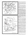
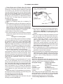
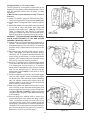
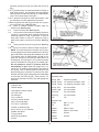
The linkage lever adjustment screw has limited adjustment capability. (See Fig. 9.) If it is not possible to adjust
the TV linkage using this screw, the length of the TV
control rod assembly must be readjusted using the following procedure. This procedure must also be followed
whenever a new TV control rod assembly is installed.
This procedure requires raising the vehicle to give
access to the linkage components at the transmission TV
control lever.
3.1Set carburetor at its minimum idle stop as described in
steps 1-3. Place shift lever in NEUTRAL and set
parking brake. Turn engine off.
3.2 Set the carburetor linkage lever adjustment screw at
approximately half-travel.
3.3 If a new TV control rod assembly is being installed,
connect the rod to the linkage lever at the carburetor.
CAUTION: The following steps involve working in
close proximity to the exhaust system. Allow the
exhaust system to cool before proceeding.
3.4Raise vehicle so there is at least 2 feet ground clearance for ease of access. MAKE SURE THE VEHICLE
IS RIGIDLY SUPPORTED ON JACK STANDS OR
WHEEL RAMPS IF A HOIST IS NOT AVAILABLE.
DO NOT USE JACKS ALONE TO SUPPORT VEHICLE.
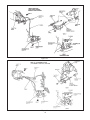
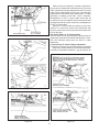
3.5Loosen the bolt on the sliding trunnion block on the TV
control rod assembly. Remove corrosion and road
grime from the control rod and free-up the trunnion
block so that it slides freely on the control rod.
3.6Push up on the lower end of the control rod to ensure
that the linkage lever at carburetor is touching firmly
against the throttle lever. Release force on rod. Rod
must stay up.
3.7Push the TV control lever on the transmission up
against its internal stop with a firm force, approximately 22 N (5 lbs). Tighten the bolt on the trunnion
block. Do not relax force on lever until bolt is tightened.
3.8Lower the vehicle and verify that the throttle lever is
still against the minimum idle stop or throttle solenoid
positioner stop. If not, repeat Steps 14 and 15.
4 Rod type Linkage Adjustment Using TV Control
Pressure
Note: This procedure requires the use of TV Pressure
Gauge with Hose (0-60 psi) T86L-70002-A or equivalent.
The results of the adjustment procedure depends on the
accuracy of the pressure gauge.
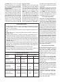
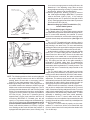
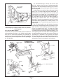
The following procedure may be used to check and/or
adjust the throttle valve (TV) control linkage using the TV
control pressure. (See Fig. 10.)
4.1Check/adjust the engine curb idle speed to specification required. Refer to the Engine/Emissions Diagnosis manual for appropriate procedure. Ensure the curb
idle speed is set to specification with and without the
throttle solenoid positioner (anti-diesel solenoid) energized, if so equipped.
4.2Attach Pressure Gauge (0-60 psi) with Hose T86L70002-A and Adapter Fitting D80L-77001-A or equivalent, to the TV port on the transmission. The pressure
Figure 10
gauge should have 2.4m (8 feet) of flexible hose to
make the gauge accessible while operating the engine.
4.3Obtain TV Control Pressure Gauge Block D84P-70332A or fabricate a block .394" ± 0.007") thick. The
following drill bit shanks may also be used in order of
preference: Letter X (.397 inch), 10mm (.3937 inch) or
25/64 (.3906 inch).
4.4Operate the engine until normal operating temperature is reached and the throttle lever is off fast idle. The
transmission fluid temperature should be approximately 38o - 72o C (100o - 150o F). Do not make
pressure check if transmission fluid is cold or too hot
to touch.
4.5Set parking brake, place shift selector in NEUTRAL,
remove air cleaner and shut off air conditioner. If
equipped with a vacuum operated throttle modulator,
disconnect and plug the vacuum line to this unit. If
equipped with a throttle solenoid positioner or an idle
speed control, do not disconnect either of these components.
11