1
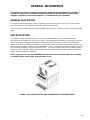
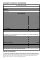
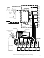
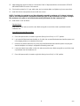
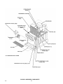
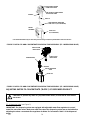
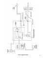
IMI CORNELIUS INC g One Cornelius Place g Anoka, MN 55303-6234
Telephone (800) 238-3600
Facsimile (612) 422-3246
Installation/Service Manual
VENTURE POST-MIX DISPENSER
(Non-Carbonated)
IMPORTANT:
TO THE INSTALLER.
It is the responsibility of
the Installer to ensure that
the water supply to the
dispensing equipment is
provided with protection
against backflow by an air
gap as defined in
ANSI/ASME A112.1.2-1979;
or an approved vacuum
breaker or other such
method as proved effective
by test.
Water pipe connections
and fixtures directly
connected to a potable
water supply shall be
sized, installed, and
maintained according to
Federal, State, and Local
Codes.
Part No. 2095
June 12, 1992
Revised: August 4, 1998
Control Code A-D
THIS DOCUMENT CONTAINS IMPORTANT INFORMATION
This Manual must be read and understood before installing or operating this equipment
Ó IMI CORNELIUS INC; 1992--98
PRINTED IN U.S.A
TABLE OF CONTENTS
Page
SAFETY INFORMATION . . . . . . . . . . . . . . . . . . . . . . . . . . . . . . . . . . . . . . . . . . . . . . . . . . . .
1
RECOGNIZE SAFETY INFORMATION . . . . . . . . . . . . . . . . . . . . . . . . . . . . . . .
UNDERSTAND SIGNAL WORDS . . . . . . . . . . . . . . . . . . . . . . . . . . . . . . . . . . . .
1
1
FOLLOW SAFETY INSTRUCTIONS . . . . . . . . . . . . . . . . . . . . . . . . . . . . . . . . .
CO2 (CARBON DIOXIDE) WARNING . . . . . . . . . . . . . . . . . . . . . . . . . . . . . . . .
SHIPPING, STORING, OR RELOCATING UNIT . . . . . . . . . . . . . . . . . . . . . . .
GENERAL INFORMATION . . . . . . . . . . . . . . . . . . . . . . . . . . . . . . . . . . . . . . . . . . . . . . . . . .
1
1
1
3
GENERAL DESCRIPTION . . . . . . . . . . . . . . . . . . . . . . . . . . . . . . . . . . . . . . . . . . . . . .
UNIT DESCRIPTION . . . . . . . . . . . . . . . . . . . . . . . . . . . . . . . . . . . . . . . . . . . . . . . . . . .
WARRANTY REFERENCE INFORMATION . . . . . . . . . . . . . . . . . . . . . . . . . . . . . . .
3
3
4
THEORY OF OPERATION . . . . . . . . . . . . . . . . . . . . . . . . . . . . . . . . . . . . . . . . . . . . . .
INSTALLATION . . . . . . . . . . . . . . . . . . . . . . . . . . . . . . . . . . . . . . . . . . . . . . . . . . . . . . . . . . . .
4
7
UNPACKING AND INSPECTION . . . . . . . . . . . . . . . . . . . . . . . . . . . . . . . . . . . . . . . .
SELECTING LOCATION . . . . . . . . . . . . . . . . . . . . . . . . . . . . . . . . . . . . . . . . . . .
INSTALLING UNIT . . . . . . . . . . . . . . . . . . . . . . . . . . . . . . . . . . . . . . . . . . . . . . . . . . . . .
INSTALLING UNIT ON COUNTERTOP . . . . . . . . . . . . . . . . . . . . . . . . . . . . . . .
FILL WATER TANK AND START REFRIGERATION SYSTEM . . . . . . . . . . .
7
7
8
8
9
CONNECTING DRIP TRAY DRAIN HOSE TO PERMANENT DRAIN . . . . .
CONNECTING PLAIN WATER INLET SUPPLY LINE TO UNIT . . . . . . . . . .
CONNECTING CONCENTRATE SOURCE LINES TO UNIT . . . . . . . . . . . .
PREPARING FOR OPERATION . . . . . . . . . . . . . . . . . . . . . . . . . . . . . . . . . . . . .
OPERATORS INSTRUCTIONS . . . . . . . . . . . . . . . . . . . . . . . . . . . . . . . . . . . . . . . . . . . . . .
9
9
10
10
13
DISPENSING VALVE LEVER . . . . . . . . . . . . . . . . . . . . . . . . . . . . . . . . . . . . . . .
DISPENSING VALVE WITH WATER LEVER . . . . . . . . . . . . . . . . . . . . . . . . . .
DISPENSING VALVES KEYED LOCK-OUT SWITCH . . . . . . . . . . . . . . . . . .
13
13
13
UNIT POWER SWITCH . . . . . . . . . . . . . . . . . . . . . . . . . . . . . . . . . . . . . . . . . . . .
DAILY PRE--OPERATION CHECK . . . . . . . . . . . . . . . . . . . . . . . . . . . . . . . . . . .
UNIT OPERATION . . . . . . . . . . . . . . . . . . . . . . . . . . . . . . . . . . . . . . . . . . . . . . . . .
ADJUSTMENTS . . . . . . . . . . . . . . . . . . . . . . . . . . . . . . . . . . . . . . . . . . . . . . . . . . . . . . .
ADJUSTING DISPENSING VALVE WATER FLOW RATE . . . . . . . . . . . . . . .
ADJUSTING WATER-TO-CONCENTRATE ‘‘RATIO’’OF DISPENSED
PRODUCT . . . . . . . . . . . . . . . . . . . . . . . . . . . . . . . . . . . . . . . . . . . . . . . . . . . . . . . .
ADJUSTING BAG-IN-BOX CONCENTRATE PUMPS OR CONCENTRATE
TANKS SYSTEM PRIMARY CO2 REGULATOR . . . . . . . . . . . . . . . . . . . . . . .
REPLENISHING CO2 SUPPLY . . . . . . . . . . . . . . . . . . . . . . . . . . . . . . . . . . . . . .
REPLENISHING CONCENTRATE SUPPLY . . . . . . . . . . . . . . . . . . . . . . . . . . .
CHANGING DISPENSED PRODUCT FLAVOR . . . . . . . . . . . . . . . . . . . . . . . .
CLEANING AND SANITIZING . . . . . . . . . . . . . . . . . . . . . . . . . . . . . . . . . . . . . . . . . . .
13
13
14
14
14
DAILY CLEANING OF UNIT . . . . . . . . . . . . . . . . . . . . . . . . . . . . . . . . . . . . . . . .
WEEKLY CLEANING OF DISPENSING VALVES . . . . . . . . . . . . . . . . . . . . . .
SANITIZING SYRUP SYSTEMS . . . . . . . . . . . . . . . . . . . . . . . . . . . . . . . . . . . . .
CLEANING DROP-IN REFRIGERATION ASSEMBLY CONDENSER COIL
CHECKING ICE WATER BATH . . . . . . . . . . . . . . . . . . . . . . . . . . . . . . . . . . . . . .
15
15
15
15
15
i
14
14
14
14
14
15
2095
TABLE OF CONTENTS (cont’d)
Page
SERVICE AND MAINTENANCE . . . . . . . . . . . . . . . . . . . . . . . . . . . . . . . . . . . . . . . . . . . . .
17
PREPARING UNIT FOR SHIPPING, STORING, OR RELOCATING . . . . . . . . . .
17
HOOD AND FRONT PANEL REMOVAL . . . . . . . . . . . . . . . . . . . . . . . . . . . . . . . . . .
HOOD REMOVAL. . . . . . . . . . . . . . . . . . . . . . . . . . . . . . . . . . . . . . . . . . . . . . . . . .
FRONT ACCESS PANEL REMOVAL . . . . . . . . . . . . . . . . . . . . . . . . . . . . . . . . .
PERIODIC INSPECTION . . . . . . . . . . . . . . . . . . . . . . . . . . . . . . . . . . . . . . . . . . . . . . .
ADJUSTMENTS . . . . . . . . . . . . . . . . . . . . . . . . . . . . . . . . . . . . . . . . . . . . . . . . . . . . . . .
ADJUSTING PRIMARY CO2 REGULATOR . . . . . . . . . . . . . . . . . . . . . . . . . . .
ADJUSTING DISPENSING VALVES WATER FLOW RATE . . . . . . . . . . . . .
17
17
17
17
19
19
19
ADJUSTING WATER-TO-CONCENTRATE (”RATIO”) OF DISPENSED
PRODUCT . . . . . . . . . . . . . . . . . . . . . . . . . . . . . . . . . . . . . . . . . . . . . . . . . . . . . . . .
CLEANING AND SANITIZING . . . . . . . . . . . . . . . . . . . . . . . . . . . . . . . . . . . . . . . . . . .
DAILY CLEANING OF UNIT . . . . . . . . . . . . . . . . . . . . . . . . . . . . . . . . . . . . . . . .
SANITIZING POST-MIX SYRUP SYSTEMS . . . . . . . . . . . . . . . . . . . . . . . . . .
CLEANING DROP-IN REFRIGERATION ASSEMBLY CONDENSER COIL . . . .
20
22
22
22
25
CHECKING ICE WATER BATH . . . . . . . . . . . . . . . . . . . . . . . . . . . . . . . . . . . . . . . . . .
CLEANING WATER TANK . . . . . . . . . . . . . . . . . . . . . . . . . . . . . . . . . . . . . . . . . .
REPLENISHING CO2 SUPPLY . . . . . . . . . . . . . . . . . . . . . . . . . . . . . . . . . . . . . .
REPLENISHING CONCENTRATE SUPPLY . . . . . . . . . . . . . . . . . . . . . . . . . . . . . . .
BAG-IN-BOX CONCENTRATE SUPPLY . . . . . . . . . . . . . . . . . . . . . . . . . . . . .
CONCENTRATE TANK CONCENTRATE SUPPLY . . . . . . . . . . . . . . . . . . . .
CONCENTRATE FLAVOR CHANGE . . . . . . . . . . . . . . . . . . . . . . . . . . . . . . . . .
25
26
27
27
27
28
28
CLEANING CO2 SYSTEM CO2 GAS CHECK VALVES . . . . . . . . . . . . . . . . . . . . .
TROUBLESHOOTING . . . . . . . . . . . . . . . . . . . . . . . . . . . . . . . . . . . . . . . . . . . . . . . . . . . . . .
28
31
TROUBLESHOOTING DISPENSING SYSTEM . . . . . . . . . . . . . . . . . . . . . . . . . . . .
31
WATER-TO-CONCENTRATE ‘‘RATIO’’TOO LOW OR TOO HIGH. . . . . . .
31
ADJUSTMENT OF DISPENSING VALVE CONCENTRATE FLOW REGULATOR
DOES NOT INCREASE TO DESIRED WATER-TO-CONCENTRATE
‘‘RATIO’’. . . . . . . . . . . . . . . . . . . . . . . . . . . . . . . . . . . . . . . . . . . . . . . . . . . . . . . . . .
31
ADJUSTMENT OF DISPENSING VALVE CONCENTRATE REGULATOR DOES
NOT DECREASE TO DESIRED WATER-TO-CONCENTRATE ‘‘RATIO’’. .
32
NO PRODUCT DISPENSED. . . . . . . . . . . . . . . . . . . . . . . . . . . . . . . . . . . . . . . .
32
ONLY CONCENTRATE DISPENSED. . . . . . . . . . . . . . . . . . . . . . . . . . . . . . . . .
32
TROUBLESHOOTING REFRIGERATION SYSTEM . . . . . . . . . . . . . . . . . . . . . . . .
32
COMPRESSOR DOES NOT OPERATE . . . . . . . . . . . . . . . . . . . . . . . . . . . . . .
32
COMPRESSOR WILL NOT STOP AFTER SUFFICIENT ICE BANK IS
PRODUCED. . . . . . . . . . . . . . . . . . . . . . . . . . . . . . . . . . . . . . . . . . . . . . . . . . . . . .
33
COMPRESSOR OPERATES CONTINUOUSLY BUT DOES NOT FORM
SUFFICIENT ICE BANK. . . . . . . . . . . . . . . . . . . . . . . . . . . . . . . . . . . . . . . . . . . .
33
AGITATOR MOTOR NOT OPERATING. . . . . . . . . . . . . . . . . . . . . . . . . . . . . . .
33
WARRANTY . . . . . . . . . . . . . . . . . . . . . . . . . . . . . . . . . . . . . . . . . . . . . . . . . . . . . . . . . . . . . .
34
LIST OF FIGURES
FIGURE 1. SIX-FLAVOR VENTURE NON-CARBONATED POST-MIX
DISPENSER . . . . . . . . . . . . . . . . . . . . . . . . . . . . . . . . . . . . . . . . . . . . . . . . . . . . . . . . . .
2095
ii
3
TABLE OF CONTENTS (cont’d)
Page
LIST OF FIGURES (CONT’D)
FIGURE 2. FLOW DIAGRAM (SIX-FLAVOR UNIT SHOWN) . . . . . . . . . . . . . . . .
FIGURE 3. INLET SUPPLY LINE CONNECTIONS (SIX-FLAVOR UNIT
SHOWN) . . . . . . . . . . . . . . . . . . . . . . . . . . . . . . . . . . . . . . . . . . . . . . . . . . . . . . . . . . . . .
FIGURE 4. DISPENSER COMPONENTS . . . . . . . . . . . . . . . . . . . . . . . . . . . . . . . . .
FIGURE 5. RATIO CUP AND CONCENTRATE DIVERSION TUBE ASSEMBLY
(SF-1 DISPENSING VALVE) . . . . . . . . . . . . . . . . . . . . . . . . . . . . . . . . . . . . . . . . . . . .
FIGURE 6. RATIO CUP AND CONCENTRATE DIVERSION TUBE ASSEMBLY
(UF-1 DISPENSING VALVE) . . . . . . . . . . . . . . . . . . . . . . . . . . . . . . . . . . . . . . . . . . . .
FIGURE 7. CO2 GAS CHECK VALVE ASSEMBLY . . . . . . . . . . . . . . . . . . . . . . . . .
FIGURE 8. WIRING DIAGRAM . . . . . . . . . . . . . . . . . . . . . . . . . . . . . . . . . . . . . . . . . .
5
12
18
20
20
28
29
LIST OF TABLES
TABLE 1. DESIGN DATA . . . . . . . . . . . . . . . . . . . . . . . . . . . . . . . . . . . . . . . . . . . . . . .
TABLE 2. LOOSE-SHIPPED PARTS . . . . . . . . . . . . . . . . . . . . . . . . . . . . . . . . . . . . .
iii
4
7
2095
SAFETY INFORMATION
Recognize Safety Information
This is the safety-alert symbol. When you see this
symbol on our machine or in this manual, be alert to
the potentially of personal injury.
Follow recommended precautions and safe operating
practices.
Understand Signal Words
A signal word - DANGER, WARNING, OR CAUTION
is used with the safety-alert symbol. DANGER identifies the most serious hazards.
Safety signs with signal word DANGER or WARNING
are typically near specific hazards.
General precautions are listed on CAUTION safety
signs. CAUTION also calls attention to safety messages in this manual.
DANGER
WARNING
CAUTION
Follow Safety Instructions
Carefully read all safety messages in this manual and on your machine safety signs. Keep safety signs in
good condition. Replace missing or damaged safety signs. Learn how to operate the machine and how to
use the controls properly. Do not let anyone operate the machine without instructions. Keep your machine in
proper working condition. Unauthorized modifications to the machine may impair function and/or safety and
affect the machine life.
CO2 (Carbon Dioxide) Warning
CO2 Displaces Oxygen. Strict Attention must be observed in the prevention of CO2 (carbon dioxide)
gas leaks in the entire CO2 and soft drink system. If a CO2 gas leak is suspected, particularly in a
small area, immediately ventilate the contaminated area before attempting to repair the leak. Personnel exposed to high concentration of CO2 gas will experience tremors which are followed rapidly by
loss of consciousness and suffocation.
Shipping, Storing, Or Relocating Unit
CAUTION: Before shipping, storing, or relocating the Unit, syrup systems must be sanitized and all
sanitizing solution must be purged from the syrup systems. All water must also be purged from the
plain and carbonated water systems. A freezing ambient environment will cause residual sanitizing
solution or water remaining inside the Unit to freeze resulting in damage to the internal components.
1
2095
THIS PAGE LEFT BLANK INTENTIONALLY
2095
2
GENERAL INFORMATION
This manual is a guide for installing, operating, and maintaining this equipment. Refer to Table of
Contents for page location of detailed information pertaining to questions that may arise during
installation, operation, service and maintenance, or troubleshooting this equipment.
GENERAL DESCRIPTION
This section gives the description, theory of operation, and design data for the Five and Six-Flavor Venture
Non-Carbonated Post-Mix Dispensers (hereafter referred to as the Units).
This Unit must be installed and serviced by a qualified Service Person. This Unit contains no User serviceable
parts.
UNIT DESCRIPTION
The Units are compact with high-impact and corrosion resistant moulded lower housings and may be
island-mounted or installed on a front or rear counter. Their refrigeration assemblies are the drop-in type which
can be removed for service and maintenance. Adjustable syrup flow regulators, located on the dispensing
valves, are easily accessible to control Water-To-Concentrate ‘‘Ratio’’of the dispensed product. All Units have
electric dispensing valves. These Unit are equipped with a 1/3-H.P. refrigeration assembly. Installation of Unit on
the countertop, installation of LOOSE-SHIPPED PARTS, connection of plain water and concentrate supplies,
adjustment of CO2 regulator, filling water tank with water, and plugging the Unit power cord into an electrical
outlet is all that is required for operation.
NOTE: Optional 4-inch Legs (P/N 314744000) that will elevate the Unit 4-inches above the countertop
are available. When ordering legs, order a quantity of four.
FIGURE 1. SIX-FLAVOR VENTURE NON-CARBONATED POST-MIX DISPENSER
3
2095
WARRANTY REFERENCE INFORMATION
Warranty Registration Date
(to be filled out by customer)
Unit Part Number:
Serial Number:
Install Date:
Local Authorized
Service Center:
Table 1. Design Data
Unit Part No.
Five-Flavor Unit
Five-Flavor Unit W/illuminated Merchandiser
Six-Flavor Unit
Six-Flavor Unit W/illuminated Merchandiser
Overall Dimensions:
Width
Height
Depth
Weights: (approximate)
Shipping (Cartoned Weight)
Dry Weight (Approx.)
Ice Bank Weight
Drop in Refrigeration Assembly
Dispensing Rate:
412155
412165
412156
412166
16 inches
27-5/8 inches
24-1/2 inches
110 lbs.
100 lbs.
31 lbs
58 lbs
650 Drinks (see NOTE)
NOTE: Number of 12-oz. drinks dispensed at 40°F or below when syrup and water inlet temperature
and ambient temperature are at 75°F.
Water Tank Capacity (no ice bank) approximate:
Refrigerant Requirement
Ambient Operating Temperature
Water Inlet Pressure Range
Electrical Requirements:
Legs
9-3/4 gallons
See Unit Nameplate
40°F to 100°F
25-45 PSI
See Unit Nameplate
(Optional) see NOTE below
NOTE: Optional 4-inch Legs (P/N 314744000) that will elevate the Unit 4-inches above the countertop
are available. When ordering the legs, order a quantity of four.
THEORY OF OPERATION
The Unit was set up at the factory to dispense all non-carbonated drinks. A CO2 cylinder delivers carbon dioxide
(CO2) gas through an adjustable CO2 regulator to the Bag-in-Box syrup pumps. When a dispensing valve is
opened, the syrup pump starts and pumps syrup through the syrup lines to the dispensing valve. Plain water is
pushed through the Unit cooling coils to to dispensing valve. Syrup and water meet simultaneously at the
dispensing valve resulting in a non-carbonated drink being dispensed.
2095
4
WATER
SOURCE
WATER FILTER INSTALLATION
FOR FILTERS WITHOUT
BUILT-IN WATER SHUTOFF VALVE
1
WATER MANIFOLD
2
SHUTOFF
VALVE
3
FILTER
4
LINE LEGEND
CO2
PLAIN WATER
SYRUP
5
PLAIN WATER
COOLING COILS
6
DISPENSER
CO2 MANIFOLD
CHECK VALVE
PRIMARY REGULATOR
(70-80 PSI)
SYRUP PUMPS
CO2 CYLINDER
BAG-IN-BOX SYRUP CONTAINERS
FIGURE 2. FLOW DIAGRAM (SIX-FLAVOR UNIT SHOWN)
5
2095
THIS PAGE LEFT BLANK INTENTIONALLY
2095
6
INSTALLATION
This section covers unpacking and inspection, selecting location, installing Unit, preparing for operation, and
Unit operation.
UNPACKING AND INSPECTION
(see Figure 4).
Note: The Unit was thoroughly inspected before leaving the factory and the carrier has accepted and
signed for it. Any damage or irregularities should be noted at the time of delivery (or not later than 15
days from date of delivery) and immediately reported to the delivering carrier. Request a written
inspection report from Claims Inspector to substantiate any necessary claim. File claim with the
delivering carrier, not with IMI Cornelius Inc.
1. After Unit has been unpacked, remove shipping tape and other packing material.
2. Remove four shipping nuts that secure drop-in refrigeration assembly in Unit.
3. Remove two screws securing Unit front access panel, then pull out on bottom of panel to remove.
4. Unpack LOOSE-SHIPPED PARTS. Make sure all items are present and in good condition.
Table 2. Loose-Shipped Parts
Item
No.
Part No.
Name
Qty.
1
317659039
Drip Tray
1
2
317660000
Cup Rest
1
3
3573
Cover, Back Access Hole
1
4
187254000
Screw, Sheet Metal, Phil Truss Hd; Type A, No. 6 by 3/8-inch. Long
2
5
318523-088
Baffle & O-Ring (see NOTE)
1
NOTE: BAFFLE & O-RING (item 5) is LOOSE-SHIPPED with Units equipped with Cornelius SF-1
dispensing valves. The baffle & O-ring is to be used only when dispensing concentrate that does not
contain pulp.
SELECTING LOCATION
WARNING: To avoid possible fatal electrical shock or serious injury to the operator, it is
highly recommended that a GFI (ground fault circuit interrupt) be installed in the electrical
circuit for the domestic Units. It is required that an ELCB (earth leakage circuit breaker) be
installed in the electrical circuit for the export Units.
This Unit may be island-mounted or installed on a front or rear counter. Locate the Unit so the following
requirements are satisfied.
1. The Unit must be installed near a properly grounded electrical outlet with proper electrical requirements.
The electrical circuit must be properly fused (‘‘slow-blow’’type fuse) or the circuit must be connected
through an equivalent HACR circuit breaker. The electrical outlet must be accessible for ease of connecting
and disconnecting the Unit power cord. No other electrical equipment should be connected to this circuit.
ALL ELECTRICAL WIRING MUST CONFORM TO NATIONAL AND LOCAL ELECTRICAL CODES.
CAUTION: Do not place or store anything on top of the Unit.
7
2095
2. Clearance above top of the Unit must be open to the ceiling. A minimum clearance of 12-inches must be
maintained on the back side of the Unit and a minimum of 6-inches clearance to the nearest obstruction
must be maintained on both sides of the Unit. These clearances must be provided to allow for proper air
flow through the Unit to cool the refrigeration system. The Unit must be located close to a permanent drain
to route the Unit drip tray and water tank drain hoses to the drain.
INSTALLING UNIT
CAUTION: This Unit is intended for indoor installation only. Do not install this Unit in an
outdoor environment which would expose it to the outside elements.
INSTALLING UNIT ON COUNTERTOP
The drip tray drain hose, water tank drain hose, and the Unit power cord may either be routed out through access
hole on back of the Unit or they may be routed down through hole cut in the countertop under front of the Unit. The
concentrate source inlet lines and the plain water source inlet line that are to be connected to the Unit behind the front
access panel may either be routed through back access hole or they may be routed up through hole cut in the
countertop up to the Unit.
1. Out Unit base back access hole -- Route drip tray drain hose, water tank drain hose, and the Unit power
cord out Unit base back access hole. The concentrate and plain water source inlet lines that are to be
connected to the Unit will be routed in through the back access hole up up to front of the Unit for
connection to the Unit.
Through Hole Cut in Countertop -- Place Unit in operating location on the countertop flush with the
countertop edge. Cut hole in the countertop directly below the front bulkhead of the Unit to allow routing the
drip tray drain hose, water tank drain hose, and the Unit power cord down through the hole and for routing
the concentrate and plain water source inlet lines up through hole to connections on front of the Unit. Install
COVER, BACK ACCESS HOLE (item 3) over Unit back access hole.
2. To comply with NSF International (NSF) requirements within the United States, the Unit must be sealed to
the countertop and all access holes to the Unit base must be closed and sealed. Proceed as follows to seal
the Unit base.
A.
Tilt Unit up to expose bottom of base.
B.
Liberally apply silastic sealant such as Dow Corning RTV 731 or equivalent on base bottom edges.
NOTE: Do not move Unit after positioning or seal from base to countertop will be broken.
C.
Lower Unit into operating position on the countertop to complete seal from base to countertop.
D.
Apply additional sealant around bottom of base. Seal must have a minimum radius of 1/2--inch to
prevent crevices and to insure a complete seal.
E.
All access holes to the Unit base must be closed and sealed.
3. BAFFLE & O-RING (item 5) is LOOSE-SHIPPED only with Units equipped with Cornelius SF-1 dispensing
valves. The baffle & O-ring is only to be used when dispensing concentrate that does not contain pulp.
A.
Remove dispensing valve nozzle
B.
Install baffle on the dispensing valve.
C.
Replace nozzle on dispensing valve.
2095
8
FILL WATER TANK AND START REFRIGERATION SYSTEM
(see Figure 4)
1. Make sure plug in water tank drain hose is secure.
NOTE: Use low-mineral-content water where a local water problem exists.
2. Remove plug from drop-in refrigeration assembly platform water fill hole. Fill water tank with clean water to
top off stainless steel coils in the coil basket. USE LOW-MINERAL-CONTENT WATER WHERE A LOCAL
WATER PROBLEM EXISTS.
3. Install plug in water fill hole.
4. Place dispensing valves keyed lock-out switch, located on right side (facing front of Unit) in “OFF”position.
5. Place Unit power switch, located on right side (facing front of Unit), in ‘‘OFF’’position.
WARNING: The Unit must be electrically grounded to avoid possible fatal electrical shock
or serious injury to the operator. The Unit power cord is equipped with a three-prong plug.
If a three--hole (grounded) electrical outlet is not available, use an approved method to
ground the Unit.
6. Plug Unit power cord into a grounded electrical outlet with proper electrical requirements.
7. Place Unit power switch in ‘‘ON’’position. The compressor, condenser fan motor, and agitator motor will
start and begin forming an ice bank. When a full ice bank has been formed, the compressor and condenser
fan motor will stop but the agitator motor will continue to operate circulating ice water bath in the water
tank.
CONNECTING DRIP TRAY DRAIN HOSE TO PERMANENT DRAIN
NOTE: Drip tray drain hose routed to a waste container is not recommended due to sanitation and
cleaning problems. Connection of drain hose to a permanent drain is recommended.
1. Preferably, route lower end of drip tray drain hose and the water tank drain hose to a permanent drain.
2. Place DRIP TRAY (item 1) in position on Unit, then install CUP REST (item 2).
CONNECTING PLAIN WATER INLET SUPPLY LINE TO UNIT
(see Figures 2 and 4)
NOTE: IMI Cornelius Inc. recommends that a water shutoff valve and water filter be installed in the
plain water source inlet line to be connected to the Unit. The plain water source water pressure must
not exceed 45-psi. If water pressure exceeds 45-psi, a water pressure regulator must be used to
regulate the water pressure.
The plain water source to the equipment shall be installed with adequate back flow protection to
comply with applicable Federal, State, and local laws.
1. Make sure plain water source inlet line meets specifications stated in the previous NOTE, then route plain
water source line to location behind the Unit front access panel.
2. Connect plain water source inlet line to barbed tee fitting located in the plain water line behind the front
access panel.
9
2095
CONNECTING CONCENTRATE SOURCE LINES TO UNIT
(see Figures 2 and 3)
Proceed as follows to connect concentrate source lines to the Unit barbed stainless-steel concentrate inlet
tubes.
NOTE: The barbed stainless-steel concentrate inlet tubes, located on front of the Unit, are labeled to
identify the dispensing valves they serve. For example, the barbed concentrate inlet stainless-steel
tube labeled “1” provides concentrate to be dispensed from No. 1 dispensing valve.
1. Route concentrate source lines (to be numbered for identification) from the concentrate source location up
to the Unit.
2. Connect the numbered concentrate source lines to the corresponding labeled Unit barbed stainless-steel
concentrate inlet tubes.
PREPARING FOR OPERATION
1. Make sure DRIP TRAY (item 1) and CUP REST (item 2) are in place on Unit.
2. Open plain water inlet supply line shutoff valve.
3. Make sure the electric dispensing valve keyed lock-out switch (left-side facing front of Unit) is in the ‘‘ON’’
(vertical) position
4. Dispense from all dispensing valves to purge all air from plain water systems.
5. Check entire plain water system for leaks and tighten any loose connections.
6. The dispensing valves adjustable water flow regulators have been factory adjusted and should require no
further adjustment. If re-adjustment should be necessary, adjust dispensing valves water flow rates as
instructed in SERVICE AND MAINTENANCE section of this manual.
WARNING: CO2 displaces oxygen. Strict attention must be observed in the prevention of
CO2 (carbon dioxide) gas leaks in the entire CO2 and soft drink system. If a CO2 gas leak is
suspected, particularly in a small area, immediately ventilate the contaminated area before
attempting to repair the leak. Personnel exposed to high concentration of CO2 gas will experience
tremors which are followed rapidly by loss of consciousness and suffocation.
CAUTION: Make sure the concentrate pumps primary CO2 regulator adjusting screw is
turned to the left (counterclockwise) until all tension is relieved from the adjusting screw
spring before opening the CO2 cylinder shutoff valve.
7. Open (counterclockwise) CO2 cylinder shutoff valve slightly to allow lines to slowly fill with gas, then open
valve fully to back-seat valve. (Back-seating valve prevents leakage around valve shaft).
8. Adjust concentrate pumps primary CO2 regulator to between 40 and 60 psi. DO NOT EXCEED MAXIMUM
PRESSURE SPECIFIED ON THE CONCENTRATE PUMPS.
9. Check all CO2 connections for leaks. Tighten any loose connections.
IMPORTANT: All concentrate systems must be sanitized before Unit is put into operation.
10. Sanitize all concentrate systems as instructed in SERVICE AND MAINTENANCE section of this manual.
11. Install full concentrate bag-in-boxes into concentrate systems.
12. Dispense from all dispensing valves to purge all air from the concentrate systems.
2095
10
13. Adjust dispensing valves for water-to-concentrate ‘‘Ratio’’of dispensed drinks as instructed in SERVICE
AND MAINTENANCE section of this manual.
14. Check entire system for CO2 gas, plain water, and concentrate leaks and tighten any loose connections.
15. Install Unit front access panel and secure with two screws.
NOTE: Circulating air, required to cool the refrigeration assembly condenser coil, is drawn in through
grille on end of the hood and is exhausted out through grille on top of the hood. For proper cooling of
the condenser coil, grille on end of the hood must be positioned over the condenser coil.
16. Install hood on Unit as follows:
Standard Hood.
Install hood on Unit and secure with screw. Make sure grille on end of the hood is positioned over the
condenser coil.
Hood With IIluminated Merchandiser.
A.
Place Unit power switch, located on right side (facing front of Unit), in ‘‘OFF’’position.
B.
Lay hood with illuminated merchandiser on it’s side, then remove illuminated merchandiser power cord
from shipping holders on underside of the hood.
C.
Hold hood in position above the Unit, then plug hood illuminated merchandiser power cord plug into
electrical adapter on the drop-in refrigeration assembly power cord.
D.
Lower hood down into position on the Unit and secure with screw. Make sure grille on end of the hood
is positioned over the condenser coil.
E.
Place Unit power switch, located on right side (facing front of Unit), in ‘‘ON’’position.
11
2095
SAFETY LATCH
BARBED
CONCENTRATE
INLET TUBES (6)
PLAIN WATER
INLET CONNECTION
2095
FIGURE 3. INLET SUPPLY LINE CONNECTIONS (SIX-FLAVOR UNIT SHOWN)
12
OPERATORS INSTRUCTIONS
This section covers operating controls, daily pre-operation check, Unit operation, adjustments, replenishing CO2
and concentrate supplies, cleaning and sanitizing, checking drop-in refrigeration assembly condenser coil for
restrictions, checking ice water bath, and periodic cleaning of CO2 gas check valves.
WARNING: Disconnect electrical power to unit to prevent personal injury before
attempting any internal maintenance. Only qualified personnel should service internal
components or electrical wiring.
CAUTION: Do not place or store anything on top of the Unit.
DISPENSING VALVE LEVER
Dispensing lever, located on bottom of the dispensing valve, need only to be pressed with cup or glass to
dispense product.
DISPENSING VALVE WITH WATER LEVER
Water lever, located on side of the dispensing valve cover, will dispense only plain water when actuated.
DISPENSING VALVES KEYED LOCK-OUT SWITCH
Dispensing valves keyed lock-out switch, located on left side of the Unit, must be in ‘‘ON’’(vertical) position to
operate electric dispensing valves. Keyed lock-out switch in ‘‘OFF’’(horizontal) position turns off electrical power
to the dispensing valves which prevents dispensing of product.
UNIT POWER SWITCH
Unit power switch, (located on right side of the Unit), must be in the ‘‘ON’’position before the Unit will operate.
DAILY PRE-- OPERATION CHECK
WARNING: CO2 displaces oxygen. Strict attention must be observed in the prevention of
CO2 (carbon dioxide) gas leaks in the entire CO2 and soft drink system. If a CO2 gas leak is
suspected, particularly in a small area, immediately ventilate the contaminated area before
attempting to repair the leak. Personnel exposed to high concentration of CO2 gas will experience
tremors which are followed rapidly by loss of consciousness and suffocation.
1. Check CO2 cylinder regulator assembly 1800-psi gage and if gage indicator is in shaded (‘‘change CO2
cylinder’’) portion of dial, CO2 cylinder is almost empty and must be replaced.
2. Make sure there is a sufficient concentrate supply. If not, replenish concentrate supply as instructed.
3. Make sure drip tray is clean and clean cup rest is in place in drip tray.
13
2095
UNIT OPERATION
1. Make sure dispensing valves keyed lock-out switch on left side of the Unit is in the ‘‘ON’’(vertical) position.
2. Press cup or glass against the dispensing valve lever and dispense until cup or glass is full of product, then
release the lever. If plain water only is desired, hold cup or glass under the dispensing valve with water
lever on its side, then actuate the lever to dispense plain water.
ADJUSTMENTS
ADJUSTING DISPENSING VALVE WATER FLOW RATE
NOTE: The dispensing valves adjustable water flow regulators are factory adjusted and should require
no futher adjustment.
Dispensing valve(s) water flow regulator(s) may be re-adjusted as instructed in SERVICE AND MAINTENANCE
section of this manual to vary amount of water dispensed.
ADJUSTING WATER-TO-CONCENTRATE ‘‘RATIO’’OF DISPENSED PRODUCT
Water-to-Syrup ‘‘Concentrate’’of the dispensed product should be checked periodically and if necessary,
adjusted as instructed in SERVICE AND MAINTENANCE section of this manual.
ADJUSTING BAG-IN-BOX CONCENTRATE PUMPS OR CONCENTRATE TANKS
SYSTEM PRIMARY CO2 REGULATOR
The bag-in-box concentrate pumps or the concentrate tanks system primary CO2 regulator should be checked
for proper pressure settings periodically and if necessary, adjusted as instructed in SERVICE AND
MAINTENANCE section of this manual.
REPLENISHING CO2 SUPPLY
WARNING: CO2 displaces oxygen. Strict attention must be observed in the prevention of
CO2 (carbon dioxide) gas leaks in the entire CO2 and soft drink system. If a CO2 gas leak is
suspected, particularly in a small area, immediately ventilate the contaminated area before
attempting to repair the leak. Personnel exposed to high concentration of CO2 gas will experience
tremors which are followed rapidly by loss of consciousness and suffocation.
The CO2 supply should be checked daily and if necessary, replenished as instructed in SERVICE AND
MAINTENANCE section of this manual.
REPLENISHING CONCENTRATE SUPPLY
The concentrate supply should be checked daily and if necessary, replenished as instructed in SERVICE AND
MAINTENANCE section of this manual. .
CHANGING DISPENSED PRODUCT FLAVOR
1. The concentrate system must first be sanitized, then a new product flavor may be connected to the
concentrate system. Refer to SERVICE AND MAINTENANCE section of this manual for instructions.
2095
14
CLEANING AND SANITIZING
DAILY CLEANING OF UNIT
Daily cleaning procedure for the Unit should be performed at end of the daily operation. Refer to SERVICE AND
MAINTENANCE Section of this manual for cleaning instructions.
WEEKLY CLEANING OF DISPENSING VALVES
The dispensing valves should be cleaned at least once a week. Refer to SERVICE AND MAINTENANCE
section of this manual for cleaning instructions.
SANITIZING SYRUP SYSTEMS
The concentrate systems should be sanitized as instructed every 90-days, or when there is a concentrate flavor
change. Refer to SERVICE AND MAINTENANCE section of this manual for instructions.
CLEANING DROP-IN REFRIGERATION ASSEMBLY CONDENSER COIL
Circulating air required to cool the refrigeration assembly condenser coil is drawn in through grille on end of the
hood and is exhausted out through grille on top of hood. Restricting air in and out of unit will decrease its cooling
efficiency. Area on top of hood must be kept free of obstructions at all times. Make sure nothing is stored on top
of the hood. The refrigeration assembly condenser coil should be periodically cleaned as instructed in SERVICE
AND MAINTENANCE section of this manual to maintain cooling efficiency.
CHECKING ICE WATER BATH
A ‘‘gurgle’’heard from the Unit indicates water level in the water tank is low and more water should be added for
maximum product cooling. Refer to SERVICE AND MAINTENANCE section of this manual for instructions.
15
2095
THIS PAGE LEFT BLANK INTENTIONALLY
2095
16
SERVICE AND MAINTENANCE
This section describes service and maintenance procedures to be performed on the Unit.
IMPORTANT: Only qualified personnel should service internal components or electrical wiring.
WARNING: Disconnect electrical power to Unit to prevent personal injury before attempting
any internal maintenance. Only qualified personnel should service internal components or
electrical wiring.
PREPARING UNIT FOR SHIPPING, STORING, OR RELOCATING
CAUTION: Before shipping, storing, or relocating this Unit, the syrup systems must be
sanitized and all sanitizing solution must be purged from the syrup systems. All water must
also be purged from the plain and carbonated water systems. A freezing ambient
environment will cause residual water in the Unit to freeze resulting in damage to internal
components.
HOOD AND FRONT PANEL REMOVAL
HOOD REMOVAL.
NOTE: Circulating air, required to cool the refrigeration assembly condenser coil, is drawn in through
grille on end of the hood and is exhausted out through grille on top of the hood. For proper cooling of
the condenser coil, grille on end of the hood must be positioned over the condenser coil.
Standard Hood.
Loosen one screw securing hood on the Unit, then lift hood straight up and off the Unit.
Hood With Illuminated Merchandiser.
IMPORTANT: Care must be exercised when removing hood with illuminated merchandiser from the
Unit. The illuminated merchandiser’s power cord must be unplugged from an electrical adaptor located
on the drop-in refrigeration assembly power cord before the hood can be completely removed from the
Unit.
1. Place power switch, located on right side (facing front of Unit), in “OFF”position.
2. Loosen one screw securing hood on the Unit. Lift hood up off the Unit far enough to be be able to disconnect the illuminated merchandiser power cord from electrical adaptor on the drop-in refrigeration assembly
power cord, then remove hood from the Unit.
FRONT ACCESS PANEL REMOVAL
Remove two screw securing Unit front access panel, then pull out on bottom of panel to remove.
PERIODIC INSPECTION
CAUTION: Do not place or store anything on top of the hood.
17
2095
DISPENSING VALVE
KEYED LOCK-OUT
SWITCH
*
FRONT ACCESS
PANEL
POWER SWITCH
* SF-1 DISPENSING VALVE SHOWN
FIGURE 4. DISPENSER COMPONENTS
2095
18
1. Check refrigeration condenser coil for obstructions and dirt. DO NOT place objects in front of the hood air
intake grille or on top of the hood. Restricting circulating air in and out of Unit will decrease its cooling
efficiency.
2. Check dispensing valves for dripping that indicates leaking and repair as necessary.
ADJUSTMENTS
ADJUSTING PRIMARY CO2 REGULATOR
Adjusting Concentrate Pumps Primary CO2 Regulator.
(see Figure 2)
NOTE: To readjust the concentrate pumps primary CO2 regulator to a lower setting, loosen adjusting
screw lock nut, then turn screw to the left (counterclockwise) until pressure gage reads 5-psi lower
than the new setting will be. Turn adjusting screw to the right (clockwise) until the gage registers new
setting, then tighten the lock nut.
Adjust concentrate pumps primary CO2 regulator to between 40 and 60 psi. DO NOT EXCEED MAXIMUM
PRESSURE SPECIFIED ON THE CONCENTRATE PUMPS.
Adjusting Concentrate Tanks Primary CO2 Regulator.
Adjust concentrate tanks system CO2 regulator to a minimum of 45-psi.
ADJUSTING DISPENSING VALVES WATER FLOW RATE
SF-1 Dispensing Valve (see Figure 5)
1. Remove dispensing valve acorn nut, then remove cover.
2. Test dispensing valve for water flow rate in accordance to the system it will be connected to.
3. Turn dispensing valve water flow regulator labeled ‘‘WATER’’adjusting screw to the left (counterclockwise)
no more than 1/4-turn at a time for less water or to the right (clockwise) no more than 1/4-turn at a time for
more water.
4. Test dispense water flow rate and adjust the water flow regulator as many times as necessary until desired
water flow rate is achieved.
UF-1 Dispensing Valve (see Figure 6)
1. Remove cover from dispensing valve by lifting front cover up 1/4-inch and pulling forward.
2. Test dispensing valve for water flow rate in accordance to the system it will be connected to.
3. Turn dispensing valve water flow regulator adjusting screw to the left (counterclockwise) for less water or to
the right (clockwise) for more water.
4. Test dispense water flow rate and adjust the water flow regulator as many times as necessary until desired
water flow rate is achieved.
19
2095
ADJUSTABLE WATER
FLOW REGULATOR
*NOZZLE
ADJUSTABLE CONCENTRATE
FLOW REGULATOR
BAFFLE
CONCENTRATE DIVERSION
TUBE ASS’Y (P/N 319540-000)
WATER
CHAMBER
RATIO CUP
(P/N 311100-000)
*Concentrate distributor may be removed by first removing nozzle, then pull distributor down and off valve.
FIGURE 5. RATIO CUP AND CONCENTRATE DIVERSION TUBE ASSEMBLY (SF-1 DISPENSING VALVE)
WATER FLOW
REGULATOR
SYRUP FLOW
REGULATOR
INNER NOZZLE
NOZZLE
SYRUP DIVERSION
TUBE
RATIO CUP
FIGURE 6. RATIO CUP AND CONCENTRATE DIVERSION TUBE ASSEMBLY (UF-1 DISPENSING VALVE)
ADJUSTING WATER-TO-CONCENTRATE (”RATIO”) OF DISPENSED PRODUCT
CAUTION: To prevent any water or syrup leaks at the valves, be sure that all valve latches
are secure.
SF-1 Dispensing Valve (see Figure 5)
IMPORTANT: The dispensing valves are equipped with adjustable water flow regulators to control
water flow rate of the valves. Make sure water flow rate of the dispensing valves are as desired before
adjusting the valves concentrate flow regulators for Water-To-Concentrate ‘‘Ratio’’of the dispensed
drinks.
2095
20
Adjust Water-to-Concentrate ‘‘Ratio’’of dispensed drink by using Syrup By-Pass Assembly (P/N 319540000),
Baffle (P/N 318754011) and Ratio Cup (P/N 311100000) as follows:.
1. Remove acorn nut securing dispensing valve cover, then remove the cover.
2. Remove nozzle from the dispensing valve.
3. Install Baffle (P/N 318754-011) on the dispensing valve, then replace the Nozzle.
4. Install concentrate diversion tube assembly on the dispensing valve by pushing rubber end of the diversion
tube upon the baffle inside the nozzle.
NOTE: Refer to concentrate manufacturer’s recommendations on the concentrate package for
Water--to-Concentrate ‘‘Ratio’’of the dispensed product.
5. Hold container under dispensing valve. Open dispensing valve and dispense just enough concentrate to fill
the concentrate diversion tube.
6. Hold large chamber of ratio cup under the dispensing valve nozzle. Place free end of the concentrate
diversion tube into concentrate chamber marked for the proper ratio. Open the dispensing valve and
dispense approximately five ounces of water into the ratio cup. Water and concentrate levels should be
even in the ratio cup.
7. If water and syrup concentrate levels are not even in the ratio cup, turn the dispensing valve concentrate
flow regulator labeled ‘‘SYRUP’’adjusting screw to the left (counterclockwise) no more than 1/4-turn at a
time for less contrate or to the right (clockwise) no more than 1/4-turn at a time for more concentrate.
8. Repeat Water-to-Concentrate ‘‘Ratio’’test and adjust the concentrate flow regulator as many times as
necessary until proper ratio of dispensed drink is achieved.
9. Remove the concentrate diversion tube assembly, Nozzle, and the Baffle from the dispensing valve.
10. Replace nozzle on the dispensing valve.
11. Replace dispensing valve cover and secure with acorn nut.
UF-1 Dispensing Valve (see Figure 6)
IMPORTANT: The dispensing valves are equipped with adjustable water flow regulators to control
water flow rate of the valves. Make sure water flow rate of the dispensing valves are as desired before
adjusting the valves concentrate flow regulators for Water-To-Concentrate ‘‘Ratio’’of the dispensed
drinks.
Adjust Water-To-Concentrate (”Ratio”) of dispensed product by using ratio cup (P/N 311100000) and Syrup
Diversion Tube Assembly (P/N 319540000) as follows:
1. Remove cover from the dispensing valve by lifting cover up 1/4-inch and pulling cover forward.
2. Install syrup diversion tube assembly on the dispensing valve by pushing rubber end of the syrup diversion
tube up on syrup outlet of the inner nozzle.
NOTE: Refer to syrup Manufacturer’s recommendations on the concentrate package for
Water-To-Concentrate (“Ratio”) of the dispensed product.
3. Dispense just enough to fill the concentrate diversion tube with concentrate.
4. Hold large chamber of the ratio cup under the dispensing valve nozzle. Place free end of the syrup
diversion tube into syrup chamber marked for proper ratio. Dispense approximately six ounces of water into
the ratio cup. Water and concentrate levels should be even in the ratio cup.
NOTE: Adjusting screws stops are built into the dispensing valve to prevent leakage when the screws
are adjusted clockwise too far. Stop adjusting clockwise when turning resistance increases. Turn
screw counterclockwise 1-1/2 turns after the stop is contacted.
21
2095
5. If water and concentrate levels are not even in the ratio cup, turn the dispensing valve concentrate flow
regulator labeled ‘‘SYRUP’’adjusting screw to the left (counterclockwise) no more than 1/4-turn at a time
for less concentrate or to the right (clockwise) no more than 1/4-turn at a time for more concentrate.
6. Repeat Water-To-Concentrate (“Ratio”) test and adjust concentrate flow regulator as many times as
necessary until proper ratio of dispensed drink is achieved.
7. Remove syrup diversion tube assembly from the dispensing valve.
8. Install dispensing valve front cover.
CLEANING AND SANITIZING
DAILY CLEANING OF UNIT
1. Remove cup rest from the drip tray.
2. Wash drip tray in place on the Unit, then rinse drip tray with hot water allowing water to drain out through
the drain hose.
3. Wash cup rest, then rinse the cup rest with clean water. Install cup rest in the drip tray.
4. Clean all external surfaces of the Unit with a sponge. Rinse out the sponge with clean water, then wring
excess water out of the sponge and wipe off all external surfaces on the Unit. Wipe Unit dry with a clean
soft cloth. DO NOT USE ABRASIVE CLEANERS.
5. Remove nozzle and syrup diffusers from the dispensing valves. Place nozzles and syrup diffusers in
sanitizing solution.
6. Wash the nozzles and syrup diffusers in sanitizing solution, then rinse them with potable water.
7. Re-install nozzles and syrup diffusers back on the dispensing valves.
SANITIZING POST-MIX SYRUP SYSTEMS
IMPORTANT: Only qualified Service Personnel should perform sanitizing procedure on the post-mix
syrup systems.
The post-mix syrup systems should be sanitized every 90-days using a non-scented household liquid bleach
containing a 5.25 % sodium hypochlorite concentration. Proceed as follows to sanitize the post-mix syrup
systems.
1. Disconnect syrup supplies from syrup systems.
2. Rinse quick disconnects (syrup tanks systems) or bag-in-box connectors (syrup bag-in-box systems) in
warm potable water.
STEP 1. WASH SYRUP SYSTEMS
3. Using a clean syrup tank (syrup tank system) or a five-gallon container (bag-in-box system), prepare a full
tank or container of liquid dishwasher detergent by using 70_F (21_C) to 100_F (38_C) potable water
and 0.5 oz. (15 ml) of liquid dishwasher detergent to one gallon of potable water. Stir detergent solution to
thoroughly mix the solution.
4. Syrup Tank Systems.
A.
Observe and note CO2 pressure setting on the syrup tanks CO2 regulator, then re-adjust CO2
regulator to 60 to 80-psi. Pressurize syrup tank containing detergent solution to 60 to 80-psi.
B.
Connect detergent solution tank, pressurized at 60 to 80-psi, into one of the syrup systems.
22
2095
Bag-in Box Syrup Systems.
C.
Install bag valves, cut from empty bag-in-box syrup containers, on ends of syrup containers syrup
outlet tubes connectors.
D.
Place all syrup outlet tubes, with bag valves on their ends, in container containing detergent solution.
5. Flush the syrup system and dispensing valve as follows:
A.
Place waste container under applicable dispensing valve.
B.
Activate the dispensing valve for one minute to purge all syrup and flush out the syrup system.
C.
Continue to activate the dispensing valve in cycles (“ON”for 15-seconds, “OFF”, then “ON”for
15-seconds). Repeat “ON”and “OFF”cycles for 15-cycles.
6. Connect detergent solution to the remaining syrup systems and flush syrup out of the syrup systems as
instructed in step 5 preceding.
7. Remove detergent solution source from the syrup system.
STEP 2. FLUSH SYRUP SYSTEMS
8. Syrup Tank Systems.
Connect syrup tank containing potable water, pressurized at 60 to 80-psi, into one of the syrup systems.
Bag-in-Box Syrup System.
Fill five-gallon container with potable water, then place all bag-in-box syrup containers syrup outlet tubes in
container containing potable water.
9. Flush detergent solution out of the syrup system and dispensing valve as follows:
A.
Place waste container under applicable dispensing valve.
B.
Activate the dispensing valve for one minute to purge all detergent solution and flush out the syrup
system.
C.
Continue to activate the dispensing valve in cycles (“ON”for 15-seconds, “OFF”, then “ON”for
15-seconds). Repeat “ON”and “OFF”cycles for 15-cycles.
10. Connect potable water source to the remaining syrup systems and flush detergent solution out of the syrup
systems as instructed in step 9 preceding.
11. Remove potable water source from the syrup system.
STEP 3. SANITIZE SYRUP SYSTEMS
12. Using a clean syrup tank (syrup tanks system) or a five-gallon container (bag-in-box system), prepare
sanitizing solution using 70_F (21_C) to100_F (38_C) potable water and 0.5 oz. (15 ml) of non-scented
household liquid bleach that contains a 5.25 % sodium hypochlorite concentration to one gallon of potable
water. This mixture must not exceed 200 PPM of chlorine. Stir sanitizing solution to thoroughly mix.
13. Syrup Tank Systems.
Connect sanitizing solution tank, pressurized at 60 to 80-psi, into one of the syrup systems.
Bag-in-Box Syrup System.
Place all bag-in-box syrup containers syrup outlet tubes in container containing sanitizing solution.
14. Sanitize the syrup system and dispensing valve as follows:
A.
Place waste container under applicable dispensing valve.
23
2095
B.
Activate the dispensing valve for one minute to purge all water from and install sanitizing solution in
the syrup system and dispensing valve.
C.
Continue to activate the dispensing valve in cycles (“ON”for 15-seconds, “OFF”, then “ON”for
15-seconds). Repeat “ON”and “OFF”cycles for 15-cycles.
15. Repeat steps13 and 14 to flush water out of and install sanitizing solution in the remaining syrup systems
and dispensing valves.
16. Remove sanitizing solution source from the syrup system.
17. Allow sanitizing solution to remain in the syrup systems for not less than 10 or no more than 15-minutes
(max.) contact time.
STEP 4. WATER FLUSH SYRUP SYSTEMS
WARNING: Flush sanitizing solution from the syrup systems as instructed. Residual
sanitizing solution left in the syrup systems could create a health hazard.
18. Fill syrup tank (syrup tank system) or a five-gallon container (bag-in-box system) with potable water.
19. Syrup Tank Systems.
Connect syrup tank containing potable water, pressurized at 60 to 80-psi, into one of the syrup systems.
Bag-in-Box Syrup System.
Place all bag-in-box syrup containers syrup outlet tubes in container containing potable water.
20. Flush sanitizing solution from the syrup system and the dispensing valve as follows:
A.
Place waste container under applicable dispensing valve.
B.
Activate the dispensing valve for one minute to purge all sanitizing solution out of the syrup system
and the dispensing valve.
C.
Continue to activate the dispensing valve in cycles (“ON”for 15-seconds, “OFF”, then “ON”for
15-seconds). Repeat “ON”and “OFF”cycles for 15-cycles.
21. Repeat steps 19 and 20 preceding to purge sanitizing solution out of the remaining syrup systems and
dispensing valves.
22. Remove potable water source from the syrup system.
STEP 5. PURGE WATER OUT OF SYRUP SYSTEMS (RESTORE OPERATION)
23. Syrup Tank Systems.
A.
Noting syrup tanks CO2 regulator pressure setting observed in step 4 preceding, readjust CO2
regulator to the observed pressure setting,
B.
Connect tanks containing syrup into syrup systems.
Bag-in-Box Syrup System.
C.
Remove all bag valves from bag-in-box syrup containers outlet tubes connectors.
D.
Connect bag-in-box syrup containers into the syrup systems.
24. Place waste container under dispensing valves. Dispense from all dispensing valves to permit syrup to
purge all potable water from the syrup systems and the dispensing valves. Continue to dispense from the
dispensing valves until only syrup is dispensed from the syrup systems and valves.
WARNING: To avoid possible personal injury or property damage, do not attempt to
remove the syrup tank cover until CO2 pressure has been released from the tank.
2095
24
25. Dispose of waste sanitizing solution in a sanitary sewer, not in a storm drain, then thoroughly rinse the
inside and the outside of the container that was used for sanitizing solution to remove all sanitizing solution
residue.
CLEANING DROP-IN REFRIGERATION ASSEMBLY CONDENSER COIL
(see Figure 4)
Excessive accumulation of dust, lint, and grease on drop-in refrigeration assembly condenser coil will restrict air
flow through the coil and cause a loss of cooling. Perform the following procedure to clean the condenser coil.
1. Unplug Unit power cord from electrical outlet.
2.
Remove hood from Unit as follows:
Standard Hood-Loosen one screw securing the hood, then lift hood straight up and off the Unit
Hood With Illuminated Merchandiser--
IMPORTANT: Care must be exercised when removing hood with illuminated merchandiser from the
Unit. The illuminated merchandiser’s power cord must be unplugged from an electrical adaptor located
on the drop-in refrigeration assembly power cord before the hood can be completely removed from the
Unit.
A.
Loosen one screw securing hood on the Unit.
B.
Lift hood up off Unit far enough to be able to disconnect the illuminated merchandiser power cord from
electrical adaptor on the drop-in refrigeration assembly power cord, then remove hood from the Unit.
3. Vacuum or use a soft brush to clean the condenser coil. If available, use low-pressure compressed air.
4. Clean dust and dirt from around top of the refrigeration assembly.
NOTE: Circulating air, required to cool the refrigeration assembly condenser coil, is drawn in through
grille on end of the hood and is exhausted out through grille on top of the hood. For proper cooling of
the condenser coil, grille on end of the hood must be positioned over the condenser coil.
5. Install Hood on Unit as follows:
Standard Hood
Install hood on Unit and secure with screw. Make sure grille on end of the hood is positioned over the
condenser coil.
Hood With Illuminated Merchandise
A.
Hold hood in position above the Unit, then plug hood illuminated merchandiser power cord into
electrical adaptor on the drop-in refrigeration assembly power cord.
B.
Lower hood down into position on the Unit and secure with screw. Make sure grille on end of the hood
is positioned over the condenser coil.
6. Plug Unit power cord into electrical outlet.
CHECKING ICE WATER BATH
A ‘‘gurgle’’heard from Unit indicates water level in water tank is low and more water should be added for
maximum cooling. Before adding more water, ice water bath and ice bank should be checked for cleanliness
and water tank coils check for excessive mineral deposit build-up.
25
2095
1. Unplug Unit power cord from electrical outlet.
2.
Remove hood from Unit as follows:
Standard Hood
Loosen one screw securing the hood, then lift hood straight up and off the Unit
Hood With Illuminated Merchandiser
IMPORTANT: Care must be exercised when removing hood with illuminated merchandiser from the
Unit. The illuminated merchandiser’s power cord must be unplugged from an electrical adaptor located
on the drop-in refrigeration assembly power cord before the hood can be completely removed from the
Unit.
A.
Loosen one screw securing hood on the Unit.
B.
Lift hood up off Unit far enough to be able to disconnect the illuminated merchandiser power cord from
electrical adaptor on the drop-in refrigeration assembly power cord, then remove hood from the Unit.
3. Remove plug from drop-in refrigeration assembly platform water fill hole.
4. Using a flashlight, inspect ice water bath and ice bank for cleanliness. Ice water bath should be clear and
ice bank free of foreign particles.
5. If cleaning of water tank is necessary, refer to CLEANING WATER TANK in this section.
6. Fill water tank with clean water to top of stainless steel coils located in coil basket. USE
LOW-MINERAL-CONTENT WATER WHERE A LOCAL WATER PROBLEM EXISTS.
7. Install plug in water fill hole.
8. Install Hood on Unit as follows:
Standard Hood
Install hood on Unit and secure with screw. Make sure grille on end of the hood is positioned over the
condenser coil.
Hood With Illuminated Merchandise
A.
Hold hood in position above the Unit, then plug hood illuminated merchandiser power cord into
electrical adaptor on the drop-in refrigeration assembly power cord.
B.
Lower hood down into position on the Unit and secure with screw. Make sure grille on end of the hood
is positioned over the condenser coil.
9. Plug Unit power cord into electrical outlet.
CLEANING WATER TANK
1. Unplug drop-in refrigeration assembly power cord, and disconnect electric dispensing valves power cord.
2. Lift drop-in refrigeration assembly up and out of Unit.
CAUTION: Never use an ice pick or other instrument to remove ice from drop--in
refrigeration assembly evaporator coils. Such practice can result in punctured refrigeration
circuit.
2095
26
3. Allow ice bank to melt. Hot water may be used to speed melting.
4. Use fiber brush and carefully clean mineral deposit build-up from agitator motor shaft and ice bank sensing
bulb.
5. Wash inside of water tank and drop-in refrigeration assembly evaporator coils, then rinse with clean water.
6. Install plug in end of water tank drain hose, then place drain hose inside of Unit.
7. Install drop-in refrigeration assembly in Unit by reversing removal procedure.
8. Return to step 6 of CHECKING ICE WATER BATH to fill water tank with water, install hood, and re-start
the Unit.
REPLENISHING CO2 SUPPLY
WARNING: CO2 displaces oxygen. Strict attention must be observed in the prevention of
CO2 (carbon dioxide) gas leaks in the entire CO2 and soft drink system. If a CO2 gas leak is
suspected, particularly in a small area, immediately ventilate the contaminated area before
attempting to repair the leak. Personnel exposed to high concentration of CO2 gas will experience
tremors which are followed rapidly by loss of consciousness and suffocation.
NOTE: When indicator on CO2 cylinder regulator assembly 1800-psi gage is in shaded (‘‘change CO2
cylinder’’) portion of dial, CO2 cylinder is almost empty and should be changed.
1. Fully close (clockwise) CO2 cylinder valve.
2. Slowly loosen CO2 regulator assembly coupling nut allowing CO2 pressure to escape, then remove
regulator assembly from empty CO2 cylinder.
3. Unfasten safety chain and remove empty CO2 cylinder.
WARNING: o avoid personal injury and/or property damage, always secure CO2 cylinder in
upright position with safety chain to prevent it from falling over. Should the valve become
accidentally damaged or broken off, CO2 cylinder can cause serious personal injury.
4. Position CO2 cylinder in upright position and secure with safety chain.
5. Make sure gasket is in place inside CO2 regulator coupling nut, then install regulator on CO2 cylinder.
6. Open (counterclockwise) CO2 cylinder valve slightly to allow lines to slowly fill with gas, then open valve
fully to back-seat valve. (back-seating valve prevents leakage around the valve shaft.)
7. Check CO2 connections for leaks. Tighten loose connections.
REPLENISHING CONCENTRATE SUPPLY
BAG-IN-BOX CONCENTRATE SUPPLY
1. Disconnect concentrate outlet tube connector from empty bag-in-box container.
2. Rinse concentrate outlet tube connectior in warm water.
3. Connect concentrate outlet tube connector to a full bag-in-box container.
4. Dispense from dispensing valve to purge all air from concentrate system and until normal dispensing
resumes.
27
2095
CONCENTRATE TANK CONCENTRATE SUPPLY
1. Remove quick disconnects from empty concentrate tank.
2. Check quick disconnects for sticky or restricted operation. Wash quick disconnects in warm water.
3. Connect quick disconnects to a full concentrate tank.
4. Dispense from dispensing valve to purge all air from concentrate system and until normal dispensing
resumes.
CONCENTRATE FLAVOR CHANGE
NOTE: If a concentrate flavor change is made, the applicable concentrate system must be sanitized.
Only qualified personnel should perform the sanitizing procedure. Refer to SANITIZING
CONCENTRATE SYSTEM in this manual section for sanitizing procedure.
1. Sanitize system in which the concentrate flavor is going to be changed.
2. Connect full tank of new flavor concentrate into the concentrate system.
3. Dispense from dispensing valve and allow concentrate to purge all potable water from the concentrate
system.
CLEANING CO2 SYSTEM CO2 GAS CHECK VALVES
(see Figure 7)
The CO2 regulators CO2 gas check valves must be inspected and serviced at least once a year under normal
conditions and after any servicing or disruption of the CO2 system. ALWAYS REPLACE BALL SEAT (QUAD
RING SEAL) EACH TIME GAS CHECK VALVES ARE SERVICED.
NOTE: COMPLETE CO2 GAS
CHECK VALVE P/N 183310000
FIGURE 7. CO2 GAS CHECK VALVE ASSEMBLY
2095
28
FIGURE 8. WIRING DIAGRAM
29
2095
THIS PAGE LEFT BLANK INTENTIONALLY
2095
30
TROUBLESHOOTING
IMPORTANT: Only qualified personnel should service internal components or electrical wiring.
WARNING: If repairs are to be made to a product system, remove quick disconnects from
the applicable product tank, then relieve the system pressure before proceeding. If repairs
are to be made to the CO2 system, stop dispensing, shut off the CO2 supply, then relieve the
system pressure before proceeding. If repairs are to be made to the refrigeration system, make sure
electrical power is disconnected from the unit.
Trouble
Probable Cause
Remedy
TROUBLESHOOTING DISPENSING SYSTEM
WATER-TO-CONCENTRATE
‘‘RATIO’’TOO LOW OR TOO
HIGH.
A.
Dispensing valve concentrate
flow regulator not properly
adjusted.
A.
Adjust Water-to-Concentrate
‘‘Ratio’’as instructed.
B.
Concentrate Tanks System.
B.
Adjust concentrate tanks CO2
regulator as instructed.
CO2 gas pressure to
concentrate tanks insufficient
to push concentrate out of
tanks.
Bag-in-Box System.
Adjust concentrate pumps CO2
regulator as instructed.
CO2 gas pressure to
concentrate pumps insufficient
to operate pumps.
ADJUSTMENT OF
DISPENSING VALVE
CONCENTRATE FLOW
REGULATOR DOES NOT
INCREASE TO DESIRED
WATER-TO-CONCENTRATE
‘‘RATIO’’.
A.
No concentrate supply.
A.
Replenish concentrate supply as
instructed.
B.
Concentrate supply container
not securely connected into
concentrate system.
B.
Securely connect concentrate
supply container into concentrate
system.
C.
Concentrate Tanks System.
C.
Adjust concentrate tanks CO2
regulator as instructed.
Concentrate tanks CO2
regulator out of adjustment.
Concentrate Bag-in-Box
System.
Adjust concentrate pumps CO2
regulator as instructed.
Concentrate pumps CO2
regulator out of adjustment.
D.
Dispensing valve syrup flow
regulator, syrup tank quick
disconnect, or syrup line
restricted.
D.
Sanitize syrup system as
instructed.
E.
Improper Baume of
concentrate.
31
E.
Replace concentrate supply.
2095
Trouble
Probable Cause
Remedy
F.
Dirty or inoperative
concentrate flow regulator.
F.
Disassemble and clean
dispensing valve concentrate flow
regulator.
G.
Tapered plastic washer inside
tube swivel nut connection
distorted from being over
tightened restricting
concentrate flow.
G.
Replace plastic washer. Make
sure it seats properly.
ADJUSTMENT OF
DISPENSING VALVE
CONCENTRATE REGULATOR
DOES NOT DECREASE TO
DESIRED
WATER-TO-CONCENTRATE
‘‘RATIO’’.
A.
Dirty or inoperative
concentrate flow regulator.
A.
Disassemble and clean
dispensing valve concentrate flow
regulator.
NO PRODUCT DISPENSED.
A.
Dispensing valves keyed
lock-out switch in ‘‘OFF’’
position.
A.
Place keyed lock-out switch in
‘‘ON’’position.
B.
No electrical power to Unit.
B.
Plug in Unit power cord or check
for blown fuse or tripped circuit
breaker.
C.
Disconnected dispensing valve
power cord.
C.
Connect dispensing valves power
cord.
D.
Disconnected or broken wiring
to dispensing valves.
D.
Connect or replace wiring.
E.
Inoperative transformer or
dispensing valve solenoids.
E.
Replace inoperative part.
A.
Water inlet supply line shutoff
valve closed.
A.
Open water inlet supply line
shutoff valve.
ADJUSTMENT OF
DISPENSING VALVE
CONCENTRATE FLOW
REGULATOR DOES NOT
INCREASE TO DESIRED
WATER-TO-CONCENTRATE
‘‘RATIO’’ (CONT’D)
ONLY CONCENTRATE
DISPENSED.
TROUBLESHOOTING REFRIGERATION SYSTEM
COMPRESSOR DOES NOT
OPERATE
2095
A.
Ice bank sufficient
A.
Refrigeration not called for.
B.
Unit power cord unplugged,
power switch in ‘‘OFF’’
position, or drop-in
refrigeration assembly power
cord unplugged.
B.
Plug in power cord(s) or place
Unit power switch (located behind
front panel) in ‘‘ON’’position.
C.
No power source (blown fuse
or tripped circuit breaker).
C.
Replace fuse or reset circuit
breaker (Note: Fuse or circuit
breaker are not part of the Unit).
D.
Inoperative Unit power switch (
or power cord unplugged.
D.
Replace power switch or plug Unit
power cord into electrical outlet.
E.
Low voltage.
E.
Voltage must be at least 103 Volts
(115VAC Unit) at compressor
terminals when compressor is
trying to start.
32
Trouble
COMPRESSOR DOES NOT
OPERATE (CONT’D)
COMPRESSOR WILL NOT
STOP AFTER SUFFICIENT
ICE BANK IS PRODUCED
(NOTE: ICE BANK SHOULD
JUST COVER CONTROL
BULB).
COMPRESSOR OPERATES
CONTINUOUSLY BUT DOES
NOT FORM SUFFICIENT ICE
BANK.
Probable Cause
Remedy
F.
Loose, disconnected or broken
wiring.
F.
Tighten connection or replace
broken wiring.
G.
Overload protector cut out;
overheated compressor.
Condenser fan motor not
operating as required.
G.
Compressor will cool enough to
restart. Do not overdraw cooling
capacity of Unit. Refer to
CONDENSER FAN MOTOR NOT
OPERATING in this section.
H.
Inoperative overload protector
or start relay.
H.
Replace inoperative part.
I.
Inoperative ice bank control
probe.
I.
Replace inoperative ice bank
control.
J.
Inoperative compressor.
J.
Call Service Person.
A.
Ice bank control capillary tube
kinked or broken.
A.
Replace ice bank control.
B.
Ice bank control stuck in
closed position.
B.
Replace ice bank control.
A.
Cooling capacity is exceeded
by overdrawing.
A.
Reduce amount of drinks drawn
per given time.
B.
Unit located in excessively hot
area or air circulation through
condenser coil is restricted.
B.
Relocate unit or check and if
necessary, clean condenser coil
as instructed.
NOTE: Ice bank freezes from bottom of the evaporator upward. A refrigerant leak or insufficient charge
might show an ice bank at bottom and not at top the of evaporator.
AGITATOR MOTOR NOT
OPERATING.
A.
Power switch in ‘‘OFF’’
position.
A.
Place power switch in ‘‘ON’’
position.
B.
Unit power cord or
refrigeration assembly power
cord unplugged.
B.
Connect power cord(s).
C.
No power source (blown fuse
or tripped circuit breaker).
C.
Replace fuse or reset circuit
breaker. (Note: Fuse or circuit
breaker are not part of Unit).
D.
Agitator motor propeller
obstructed.
D.
Remove obstruction.
E.
Low voltage.
E.
Voltage must be at least 103 volts
(115 VAC Unit) at compressor
terminals when compressor is
trying to start.
F.
Loose, disconnected, or
broken wiring.
F.
Tighten connections or replace
broken wiring.
G.
Inoperative agitator motor.
G.
Replace agitator motor as
instructed.
33
2095
WARRANTY
IMI Cornelius Inc. warrants that all equipment and parts are free from defects in material and workmanship under normal use and service. For a copy of the warranty applicable to your Cornelius, Remcor or Wilshire product, in your country, please write, fax or telephone the IMI Cornelius office nearest you. Please provide the
equipment model number, serial number and the date of purchase.
IMI Cornelius Offices
AUSTRALIA D P.O. 210, D RIVERWOOD, D NSW 2210, AUSTRALIA D (61) 2 533 3122 D FAX (61) 2 534 2166
AUSTRIA D AM LANGEN FELDE 32 D A-1222 D VIENNA, AUSTRIA D (43) 1 233 520 D FAX (43) 1-2335-2930
BELGIUM D BOSKAPELLEI 122 D B-2930 BRAASCHAAT, BELGIUM D (32) 3 664 0552 D FAX (32) 3 665 2307
BRAZIL D RUA ITAOCARA 97 D TOMAS COELHO D RIO DE JANEIRO, BRAZIL D (55) 21 591 7150 D FAX (55) 21 593 1829
ENGLAND D TYTHING ROAD ALCESTER D WARWICKSHIRE, B49 6 EU, ENGLAND D (44) 789 763 101 D FAX (44) 789 763 644
FRANCE D 71 ROUTE DE ST. DENIS D F-95170 DEUIL LA BARRE D PARIS, FRANCE D (33) 1 34 28 6200 D FAX (33) 1 34 28 6201
GERMANY D CARL LEVERKUS STRASSE 15 D D-4018 LANGENFELD, GERMANY D (49) 2173 7930 D FAX (49) 2173 77 438
GREECE D 488 MESSOGION AVENUE D AGIA PARASKEVI D 153 42 D ATHENS, GREECE D (30) 1 600 1073 D FAX (30) 1 601 2491
HONG KONG D 1104 TAIKOTSUI CENTRE D 11-15 KOK CHEUNG ST D TAIKOKTSUE, HONG KONG D (852) 789 9882 D FAX (852) 391 6222
ITALY D VIA PELLIZZARI 11 D 1-20059 D VIMARCATE, ITALY D (39) 39 608 0817 D FAX (39) 39 608 0814
NEW ZEALAND D 20 LANSFORD CRES. D P.O. BOX 19-044 AVONDALE D AUCKLAND 7, NEW ZEALAND D (64) 9 8200 357 D FAX (64) 9 8200 361
SINGAPORE D 16 TUAS STREET D SINGAPORE 2263 D (65) 862 5542 D FAX (65) 862 5604
SPAIN D POLIGONO INDUSTRAIL D RIERA DEL FONOLLAR D E-08830 SANT BOI DE LLOBREGAT D BARCELONA, SPAIN D (34) 3 640 2839 D FAX (34) 3 654 3379
USA D ONE CORNELIUS PLACE D ANOKA, MINNESOTA D (612) 421-6120 D FAX (612) 422-3255
LD004
4/21/98
2095
34
THIS PAGE LEFT BLANK INTENTIONALLY
35
2095
IMI CORNELIUS INC.
CORPORATE HEADQUARTERS:
One Cornelius Place
Anoka, Minnesota 55303-6234
(612) 421-6120
(800) 238-3600


![Service Manual VA13 Carbonator [ 002818 ]](http://vs1.manualzilla.com/store/data/006013608_1-0f8f87056a0ab013b1dd01dac3912d47-150x150.png)