1
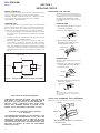
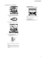
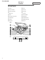
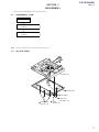
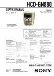
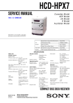
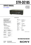
Deze download wordt u gratis aangeboden door Pick-upnaalden.nl Web : www.pickupnaalden.com Email : [email protected] Facebook : www.facebook.com/pickupnaalden Twitter : twitter.com/Pickupnaalden Google+ : https://plus.google.com/+FCaris_pickupnaalden PS-LX300USB SERVICE MANUAL US Model Canadian Model AEP Model UK Model Australian Model Ver. 1.2 2008.09 SPECIFICATIONS • IBM and PC/AT are registered trademarks of International Business Machines Corporation. • Microsoft, Windows and Windows Vista are either registered trademarks or trademarks of Microsoft Corporation in the United States and / or other countries. • Sound Forge is a trademark or registered trademark of Sony Creative Software Inc. in the United States and other countries. • All other names of systems and products are trademarks or registered trademarks of their respective owners. TM and ® marks are omitted in this manual. Motor and Platter Drive system: Belt-drive Motor: DC motor Platter: 295 mm dia. (aluminum die-cast) Speeds: 33 1/3 and 45 r/min, 2 speed Wow and flutter: Less than 0.25% (WRMS) Signal to noise ratio: More than 50 dB (DIN-B) Tone Arm Type: Dynamic balanced straight-shaped with soft damping control Effective arm length: 195 mm USB jack Power supply: USB bus power compliant (5 V, 100 mA) (The power is supplied by the PC which is connected with an attached USB cable) Output jack: Plug-in-power system (Dedicated USB jack) USB series B connector USB (full-speed) General Power requirements: North American model: 120 V AC, 60 Hz Other models: 230 – 240 V AC, 50/60 Hz Power consumption: 2W Dimensions: Approx. 420 × 95 × 360 mm (16 1/2 × 3 5/8 × 14 1/4 in) (w/h/d) Mass: 3.3 kg (7 lb 5 oz) Supplied Accessories: 45 r/min adaptor (1) Platter (with drive belt) (1) Rubber mat (1) USB cable (1) CD-ROM (1) Operating Instructions The installation guide for “Sound Forge Audio Studio LE” Design and specifications are subject to change without notice. STEREO TURNTABLE SYSTEM 9-887-948-03 Sony Corporation 2008I05-1 © 2008.09 Audio&Video Business Gourp Published by Sony Techno Create Corporation PS-LX300USB Ver. 1.1 SECTION 1 SERVICING NOTES SAFETY CHECK-OUT After correcting the original service problem, perform the following safety check before releasing the set to the customer: Check the antenna terminals, metal trim, “metallized” knobs, screws, and all other exposed metal parts for AC leakage. Check leakage as described below. LEAKAGE TEST The AC leakage from any exposed metal part to earth ground and from all exposed metal parts to any exposed metal part having a return to chassis, must not exceed 0.5 mA (500 microamperes.). Leakage current can be measured by any one of three methods. 1. A commercial leakage tester, such as the Simpson 229 or RCA WT-540A. Follow the manufacturers’ instructions to use these instruments. 2. A battery-operated AC milliammeter. The Data Precision 245 digital multimeter is suitable for this job. 3. Measuring the voltage drop across a resistor by means of a VOM or battery-operated AC voltmeter. The “limit” indication is 0.75 V, so analog meters must have an accurate low-voltage scale. The Simpson 250 and Sanwa SH-63Trd are examples of a passive VOM that is suitable. Nearly all battery operated digital multimeters that have a 2 V AC range are suitable. (See Fig. A) REPLACING THE STYLUS The life expectancy of the stylus tip is about 500 hours. To preserve good sound quality and avoid damage to your records, we recommend replacing the stylus within this time limit. For a replacement stylus, consult your nearest Sony dealer. To remove the stylus 1 Turn off and unplug the AC power cords of the turntable and amplifier. 2 Protect the stylus with the stylus cover. Stylus cover 3 Grasp the stylus holder and pull it downward away from the body of the cartridge/headshell as shown. Cartridge/headshell Stylus holder To Exposed Metal Parts on Set To install the stylus Do this procedure with the stylus protected by the stylus cover. 0.15 μF 1.5 kΩ AC voltmeter (0.75 V) 1 Grasp both sides of the stylus holder, then insert the stylus grip into the cartridge/ headshell receptacle. Stylus holder Earth Ground Fig. A. Stylus cover Stylus grip Using an AC voltmeter to check AC leakage. 2 Push up the stylus holder until it clicks so that it locks completely. Do not leave any space. Note SAFETY-RELATED COMPONET WARNING! COMPONENTS IDENTIFIED BY MARK 0 OR DOTTED LINE WITH MARK 0 ON THE SCHEMATIC DIAGRAMS AND IN THE PARTS LIST ARE CRITICAL TO SAFE OPERATION. REPLACE THESE COMPONENTS WITH SONY PARTS WHOSE PART NUMBERS APPEAR AS SHOWN IN THIS MANUAL OR IN SUPPLEMENTS PUBLISHED BY SONY. ATTENTION AU COMPOSANT AYANT RAPPORT À LA SÉCURITÉ! LES COMPOSANTS IDENTIFIÉS PAR UNE MARQUE 0 SUR LES DIAGRAMMES SCHÉMATIQUES ET LA LISTE DES PIÈCES SONT CRITIQUES POUR LA SÉCURITÉ DE FONCTIONNEMENT. NE REMPLACER CES COM- POSANTS QUE PAR DES PIÈCES SONY DONT LES NUMÉROS SONT DONNÉS DANS CE MANUEL OU DANS LES SUPPLÉMENTS PUBLIÉS PAR SONY. 2 Do not push the stylus cover forcefully. Otherwise, the exposed stylus from the cover may cause injury, or damage the stylus. NOTE FOR CHANGING THE CARTRIDGE Note: When changing the cartridge, be sure to fix by a bond. cartridge tonearm assy SONY BOND SC608LV (Part No. 7-600-000-48) or equivalent bond. - bottom view - PS-LX300USB ASSEMBLING THE TURNTABLE To remove the dust cover With the dust cover fully opened, grasp both sides of the cover, then remove it carefully. Hinge pocket Hinge 1 Move the metallic parts inside the larger gear in the direction of the arrow. Tip You can use the turntable leaving the dust cover removed. In that case, store the cover correctly. To install the dust cover Insert the hinge pockets on the dust cover into the hinges on the rear of the cabinet. 2 Carefully place the platter on the spindle. 3 Using the ribbon, loop the drive belt around the motor pully. After looping the belt, do not forget to remove the ribbon. 4 Place the rubber mat on the platter. Note When the AC power cord is plugged after assembling or moving the turntable, the turntable sometimes rotates and the torn arm descends to the platter even if START is not pressed. If this occurs, press STOP to return the tone arm to the arm stand. 3 PS-LX300USB SECTION 2 GENERAL Parts and Controls Spindle Hinge 45 r/min adaptor Tone arm Speed select button Arm stand Rubber mat Finger lift Platter SIZE SELECTOR Cartridge and headshell STOP button START button UP/DOWN button Insulator PHONO/LINE switch Dust cover USB jack Front Rear 4 This section is extracted from instruction manual. PS-LX300USB Ver. 1.1 SECTION 3 DISASSEMBLY • This set can be disassembled in the order shown below. 3-1. DISASSEMBLY FLOW SET 3-2. BOTTOM PANEL (Page 5) 3-3. USB BOARD (Page 6) Note: Follow the disassembly procedure in the numerical order given. 3-2. BOTTOM PANEL panel block bottom panel two rubbers two screws (PTPWH3 × 12) three screws (BVTP3 × 8) screw (BVTP3 × 8) 5 PS-LX300USB Ver. 1.1 3-3. USB BOARD Note: This illustration is seeing panel block from the base side. screw (PTPWH3 × 8) screw (PTPWH3 × 8) screw (PTPWH3 × 8) segregate sheet harness USB board screw (PTPWH3 × 8) harness USB board red GND white black four solders panel block 6 connector (CN602) PS-LX300USB Ver. 1.1 SECTION 4 EXPLODED VIEWS AND ACCESSORIES Note: • -XX and -X mean standardized parts, so they may have some difference from the original one. • Items marked “*” are not stocked since they are seldom required for routine service. Some delay should be anticipated when ordering these items. 4-1 • The mechanical parts with no reference number in the exploded views are not supplied. • Color Indication of Appearance Parts Example: KNOB, BALANCE (WHITE) . . . (RED) R R Parts Color Cabinet’s Color The components identified by mark 0 or dotted line with mark 0 are critical for safety. Replace only with part number specified. Les composants identifiés par une marque 0 sont critiques pour la sécurité. Ne les remplacer que par une pièce portant le numéro spécifié. OVERALL SECTION 9 8 7 10 13 11 6 USB board section 12 3 5 4 3 3 not supplied not supplied 14 2 not supplied not supplied not supplied not supplied #1 1 #1 #1 #1 1 Note: When POWER board failed, please change the board entirely. Ref. No. Part No. Description Remark 1 2 3 04 4-215-536-01 9-885-117-64 4-215-531-01 9-885-117-02 04 9-885-117-66 SCREW=PTPWH 3X12 W10 STEP POWER BOARD, COMPLETE SCREW=PTPWH 3X8 W8 TRANSFORMER (CEL), POWER (AEP, UK, Australian) TRANSFORMER (US), POWER (US, Canadian) 5 6 7 8 9 9-885-117-69 9-885-117-87 9-885-117-85 9-885-117-86 9-885-117-71 CENTER & PINION ASSY BELT (Drive belt) TURN TABLE (Platter) PAD, RUBBER (Rubber mat) DUSTCOVER Ref. No. Part No. Description 10 11 0 12 0 12 0 12 9-885-117-82 9-885-117-84 9-885-117-93 9-885-117-96 9-885-117-97 RUBBER FOOT FOR DUSTCOVER 45 RPM ADAPTER (45 r/min adaptor) CORD, POWER (US) (US, Canadian) CORD, POWER (CEL) (AEP) CORD, POWER (CEK) (UK) 0 12 13 14 #1 9-885-117-98 9-885-117-92 4-215-534-01 7-685-646-79 CORD, POWER (AU) (Australian) CORD, CONNECTION SCREW=PTPWH 3X16 W8 SCREW +BVTP 3X8 TYPE2 IT-3 Remark 7 PS-LX300USB Ver. 1.1 4-2 USB BOARD SECTION 59 61 not supplied 56 62 not supplied 58 55 57 55 knob section not supplied not supplied 52 not supplied 64 not supplied 60 62 not supplied 63 54 51 not supplied 53 53 not supplied 53 not supplied 53 Note: When USB board failed, please change the board entirely. Ref. No. 8 Part No. Description 51 52 53 54 55 4-215-538-01 4-215-530-01 4-215-532-01 9-885-117-63 4-215-523-01 SCREW PS 3X12 NUT M9 HEX 11 SCREW=PTPWH 3X8 W10 USB BOARD, COMPLETE COLLAR (D6D8X1.5) 56 57 9-885-117-68 9-885-117-75 GEAR ASSY, CAM STYLUS (N-6516) Remark Ref. No. Part No. Description 58 59 60 9-885-117-76 9-885-117-72 4-215-520-01 CARTRIDGE TONEARM ASSY SCREW BVTT 3X20 61 62 63 64 4-215-539-01 4-215-540-01 4-215-562-01 4-215-576-01 SCREW=PTPWH 3X7 W10 SCREW=BVTPW 3X10 W13 WASHER D3.2 W13 SCREW=PTPWH 3X10 W10 Remark PS-LX300USB Ver. 1.2 4-3 KNOB SECTION 119 115 121 120 107 122 not supplied M1 106 not supplied 117 118 S1 108 116 not supplied 103 109 S3 116 not supplied not supplied not supplied S2 113 104 116 103 102 not supplied not supplied not supplied 112 111 not supplied 105 not supplied 113 109 104 110 not supplied 102 101 not supplied not supplied Ref. No. Part No. Description 101 102 103 104 105 9-885-117-78 4-215-533-01 4-215-526-01 9-885-117-67 9-885-117-74 PENDULUM (L) SCREW=PTPWH 3X12 W8 SPRING SET ASSY, KNOB SHAFT (&) KNOB, PLAY STOP 106 107 108 109 110 9-885-117-81 4-215-535-01 9-885-117-77 4-215-537-01 9-885-117-70 LIFTER SCREW=PTP 3X8 FIXING SWITCH SET SCREW=PTPWH 3X10 W8 SHAFT ASSY 111 112 113 114 9-885-117-83 9-885-117-79 9-885-117-80 4-215-540-01 CONTROL PLATE PENDULUM (M) KNOB SET SCREW=BVTPW 3X10 W13 Remark Ref. No. Part No. Description Remark 115 4-215-541-01 SCREW (F 3X6.5) STEP 116 117 118 119 120 4-215-542-01 9-885-117-03 4-215-532-01 4-216-509-01 4-216-534-01 SCREW=PTP 2.6X8 ADAPTOR BOARD, COMPLETE SCREW=PTPWH 3X8 W10 HINGE HINGE PIN 121 122 M1 S1 S2 4-216-510-01 4-216-536-01 9-885-117-73 9-885-117-88 9-885-117-88 HINGE SLIDE HINGE SPRING MOTOR ASSY (TURN TABLE) SWITCH, LEAF (SPEED SETTING) SWITCH, LEAF (TONE ARM UP/DOWN DETECT) S3 9-885-117-89 SWITCH, LEAF (TONE ARM TURN DETECT) 9 PS-LX300USB Ver. 1.1 4-4 ACCESSORIES Ref. No. Part No. Description 3-198-123-13 3-198-123-22 MANUAL, INSTRUCTION (ENGLISH) MANUAL, INSTRUCTION (FRENCH, SPANISH) (Canadian, AEP) MANUAL, INSTRUCTION (GERMAN, DUTCH, ITALIAN) (AEP) MANUAL, INSTRUCTION (SWEDISH, POLISH) (AEP) APPLICATION SOFTWARE (SFAS) (CD-ROM: Sound Forge Audio Studio LE) 3-198-123-32 3-198-123-42 3-296-918-01 3-878-582-11 3-878-582-21 3-878-582-31 3-878-582-41 3-878-582-51 10 Remark MANUAL, INSTRUCTION (DANISH, FINNISH) (AEP) MANUAL, INSTRUCTION (PORTUGUESE) (AEP) MANUAL, INSTRUCTION (RUSSIAN) (AEP) MANUAL, INSTRUCTION (GREEK) (AEP) MANUAL, INSTRUCTION (CZECH, HUNGARIAN) (AEP) 3-878-582-61 3-878-582-71 9-885-117-84 9-885-117-85 9-885-117-86 MANUAL, INSTRUCTION (TURKISH) (AEP) MANUAL, INSTRUCTION (SLOVAKIAN) (AEP) 45 RPM ADAPTER (45 r/min adaptor) TURN TABLE (Platter) PAD, RUBBER (Rubber mat) 9-885-117-87 9-885-117-95 BELT (Drive belt) CABLE, USB PS-LX300USB MEMO 11 PS-LX300USB REVISION HISTORY Checking the version allows you to jump to the revised page. Also, clicking the version at the top of the revised page allows you to jump to the next revised page. Ver. Date Description of Revision 1.0 2008.02 New 1.1 2008.06 Addition of Canadian, AEP, UK and Australian models 1.2 2008.09 Addition of Ref. No. 119, 120, 121 and 122 on EXPLODED VIEWS (SMR-08139)