1
service manual
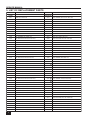
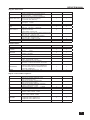
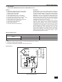
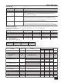
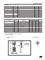
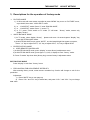
Thermal Impedance
(TA= 25°C, unless otherwise specied)
Symbol
Parameter
Junction to Case Thermal Impedance
θJC
FSCQ0765RT
Value
Unit
2.60
°C/W
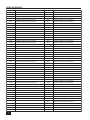
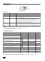
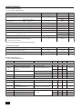
Electrical Characteristics (SenseFET Part)
(TA= 25°C, unless otherwise specified)
Parameter
Condition
Min.
Typ.
Max.
Unit
VGS= 0V, ID= 250μA
650
-
-
V
VDS= 650V,VGS= 0V
-
-
250
μA
VGS= 10V, ID=1A
-
1.4
1.6
Ω
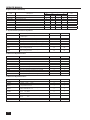
FSCQ0765RT
VGS= 0V, VDS= 25V,
-
1415
-
pF
FSCQ0765RT
VGS= 0V, VDS= 25V,
-
100
-
pF
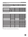
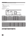
Condition
Min.
Typ.
Max.
Unit
18
20
22
KHz
Symbol
Drain-Source Breakdown Voltage
BVDSS
Zero Gate Voltage Drain Current
IDSS
Drain-Source ON-State Resistance
RDS(ON)
FSCQ0765RT
Input Capacitance
CISS
Output Capacitance
COSS
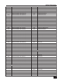
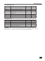
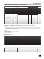
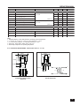
Electrical Characteristics (Continued)
(TA= 25°C unless otherwise specified)
Parameter
Symbol
Control Section
FOSC
Switching Frequency
Switching Frequency
Variation7
Feedback Source Current
∆FOSC
IFB
VFB= 5V, VCC= 18V
-25°C≤ TA≤ 85°C
0
±5
±10
%
VFB= 0.8V, VCC= 18V
0.5
0.65
0.8
mA
Maximum Duty Cycle
DMAX
VFB= 5V, VCC= 18V
92
95
98
%
Minimum Duty Cycle
DMIN
VFB= 0V, VCC= 18V
-
0
-
%
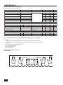
V
UVLO Threshold Voltage
Soft Start Time6
VSTART
VFB =1V
14
15
16
VSTOP
8
9
10
TSS
18
20
22
ms
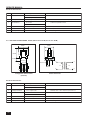
Burst Mode Section
Burst Mode Enable Feedback Voltage
VBEN
0.25
0.40
0.55
V
VBurst Mode Feedback Source Current
IBFB
VFB =0V
60
100
140
μA
Burst Mode Switching Time
TBS
VFB= 0.9V, Duty=50%
1.2
1.4
1.6
ms
Burst Mode Hold Time
TBH
VFB =0.9V → 0V
1.2
1.4
1.6
ms
VSD
VCC= 18V
70
7.5
8.0
V
4
5
6
μA
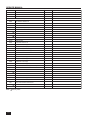
Protection Section
Shutdown Feedback Voltage
Shutdown Delay CurrentI
IDELAY
VFB= 5V, VCC= 18V
Over Voltage Protection
VOVP
VFB= 3V
11
12
1.3
V
Over Current Latch Voltage6
VOCL
VCC= 18V
0.9
1.0
1.1
V
140
-
-
°C
Thermal Shutdown
Temp7
TSD
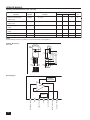
Notes:
6. These parameters, although guaranteed, are tested only in EDS (wafer test) process.
7. These parameters, although guaranteed at the design, are not tested in mass production.
21