1
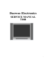
Daewoo Electronics
SERVICE MANUAL
T008
1
CONTENTS
1.
Safety Precautions………………………………………………………………………………… 3
2.
MCU and signal Processor for a PAL/NTSC TV…………………………………………………… 4
3.
Definition of A8891CPNG-**** Pin…………………………………………………………………5
4.
Remote Control Circuit Diagram and Function…………………………………………………… 6
1)User Remote……………………………………………………………………………………… 6
2)Service Remote…………………………………………………………………………………… 7
5.
Service Controlled Function………………………………………………………………………… 8
1)White balance adjustment………………………………………………………………………… 8
2)Pictureand AGC adjustment…………………………………………………………………… 8
3)Option set………………………………………………………………………………………… 9
6.
Service and Design Data…………………………………………………………………………… 13
7.
ICs Functional Description………………………………………………………………………… 14
8.
Test Point Waveforms……………………………………………………………………………… 14
9.
IC Voltages………………………………………………………………………………………… 14
10. Other……………………………………………………………………………………………
15
2
1. SAFETY PRECAUTIONS
1.
2.
3.
4.
5.
6.
7.
8.
The design of this product contains special hardware, many
circuits and components specially for safety purposes. For
continued protection, no changes should be made to the original
design unless authorized in writing by the manufacturer.
Replacement parts must be identical to those used in the original
circuits. Service should be performed by qualified personnel only.
Alterations of the design or circuitry of the products should not be
made. Any design alterations or additions will void the
manufacturer’s warranty and will further relieve the manufacturer
of responsibility for personal injury or property damage resulting
therefrom.
Many electrical and mechanical parts in the products have
special safety-related characteristics. These characteristics are
often not evident from visual inspection nor can the protection
afforded by them necessarily be obtained by using replacement
components rated for higher voltage, wattage, etc. Replacement
parts which have these special safety characteristics are identified
in the parts list of Service manual. Electrical components having
such features are identified by shading on the schematics and by
( ! ) on the parts list in Service manual. The use of a substitute
replacement which does not have the same safety characteristics
as the recommended replacement part shown in the parts list of
Service manual may cause shock, fire, or other hazards
Don’t short between the LIVE side ground and ISOLATED
(NEUTRAL) side ground or EARTH side ground when repairing.
Some model’s power circuit is partly different in the GND. The
difference of the GND is shown by the LIVE: ( ) side GND,
ISOLATED (NEUTRAL) : ( ) side GND and EARTH : (
)
side GND. Don’t short between the LIVE side GND and
ISOLATED (NEUTRAL) side GND or EARTH side GND and
never measure with a measuring apparatus (oscilloscope etc.) the
LIVE side GND and ISOLATED (NEUTRAL) side GND or
EARTH side GND at the same time. If above note will not be kept,
a fuse or any parts will be broken.
If any repair has been made to the chassis, it is recommended that
the B1 setting should be checked or adjusted (See ADJUSTMENT
OF B1 POWER SUPPLY).
The high voltage applied to the picture tube must conform with
that specified in Service manual. Excessive high voltage can
cause an increase in X-Ray emission, arcing and possible
component damage, therefore operation under excessive high
voltage conditions should be kept to a minimum, or should be
prevented. If severe arcing occurs, remove the AC power
immediately and determine the cause by visual inspection
(incorrect installation, cracked or melted high voltage harness,
poor soldering, etc.). To maintain the proper minimum level of
soft X-Ray emission, components in the high voltage circuitry
including the picture tube must be the exact replacements or
alternatives approved by the manufacturer of the complete
product.
Do not check high voltage by drawing an arc. Use a high voltage
meter or a high voltage probe with a VTVM. Discharge the
picture tube before attempting meter connection, by connecting a
clip lead to the ground frame and connecting the other end of the
lead through a 10kΩ 2W resitor to the anode button.
When service is required, observe the original lead dress. Extra
precaution should be given to assure correct lead dress in the high
voltage circuit area. Where a short circuit has occurred, those
components that indicate evidence of overheating should be
replaced. Always use the
9. manufacturer’s replacement components.
10. Isolation Check
(Safety for Electrical Shock Hazard)
After re-assembling the product, always perform an isolation
check on the exposed metal parts of the cabinet (antenna terminals,
video/audio input and output terminals, Control knobs, metal
cabinet, screwheads, earphone jack, control shafts, etc.) to be sure
the product is safe to operate without danger of electrical shock.
11. The surface of the TV screen is coated with a thin film which can
easily be damaged. Be very careful with it when handle the TV.
Should the TV screen become soiled, wipe it with a soft dry cloth.
Never rub it forcefully. Never use any cleaner or detergent on it.
(1) Dielectric Strength Test
The isolation between the AC primary circuit and all metal parts
exposed to the user, particularly any exposed metal part having a
return path to the chassis should withstand a voltage of 3000V AC
(r.m.s.) for a period of one second.
(…Withstand a voltage of 1100V AC (r.m.s.) to an appliance rated
up to 120V, and 3000V AC (r.m.s.) to an appliance rated 200V or
more, for a periode of one second.)
This method of test requires a test equipment not generally found
in the service trade.
(2) Leakage Current Check
Plug the AC line cord directly into the AC outlet (do not use a line
isolation transformer during this check.). Using a “Leakage
Current Tester”, measure the leakage current from each exposed
metal part of the cabinet, particularly any exposed metal part
having a return path to the chassis, to a known good earth ground
(water pipe, etc.). Any leakage current must not exceed 0.5mA AC
(r.m.s.).
However, in tropical area, this must not exceed 0.2mA AC
(r.m.s.).
●Alternate Check Method
Plug the AC line cord directly into the AC outlet ( do not use a
line isolation transformer during this check.). Use an AC
voltmeter having 1000 ohms per volt or more sensitivity in the
following manner. Connect a 1500Ω 10W resistor paralleled by a
0.15µF AC-type capacitor between an exposed metal part and a
known good earth ground (water pipe, etc.). Measure the AC
voltage across the resistor with the AC voltmeter. Move the
resistor connection to each exposed metal part, particularly any
exposed metal part having a return path to the chassis, and
measure the AC voltage across the resistor. Now, reverse the plug
in the AC outlet and repeat each measurement. Any voltage
measured must not exceed 0.75V AC (r.m.s.). This corresponds to
0.5mA AC (r.m.s.).
However, in tropical area, this must not exceed 0.3V AC (r.m.s.).
This corresponds to 0.2mA AC (r.m.s.)
3
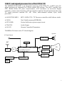
2.MCU and signal processor for a PAL/NTSC TV
The TMP8893CPNG-6RE1 is an integrated circuit for a PAL/NTSC TV. A MCU and a TV
signal processor are integrated in a 64-pin shrink DIP package. The MCU contains 8-bit
CPU, ROM, RAM, I/O ports, timer/counters, A/D converters, an on-screen display
controller, remote control interfaces, IIC bus interfaces and the Closed Caption decoder. The
TV signal processor contains PIF, SIF, Video, multi-standard chroma, Sync, RGB
processors.
◆ A8893CPNG-6RE1
MCU+OSD+CCD+ TV Processor controller with Software inside.
◆ 24C08
Non Volatile memory(EEPROM)
◆ STV9302B
Vertical deflection system output circuit.
◆ TDA7263
Audio Output
◆ SC6122
Remote Controlled Transmitter.
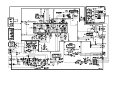
TOSHIBA G8 chassis color TV block diagram
Speaker
AV Input/Output
Audio Out
ANT
Tuner
MEMORY
SA
MCU , PIF/SIF, Video ,Chroma,
Sync, RGB processors,
H./V. driving pulse
CRT Drive
CR
V.OUT
H.OUT
IR transmit
IR receive
Power
Supply
4
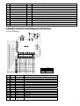
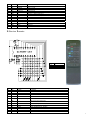
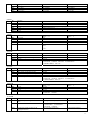
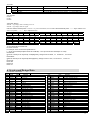
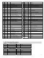
3. Definition of A8891CPNG-6RE1 Pin
NO.
Function
EyeCare or X-ray
Thermal resistance
3
4
5
6
7
8
9
10
11
12
13
14
15
16
17
18
19
20
21
22
23
24
25
26
27
28
29
30
31
32
33
34
Thermal resistance(FS)
KEY
VSS
RESET
XOUT
XIN
TEST
VDD
VSS
TV DEF AGND
FBP in
H out
HAFC 1
V saw
V out
AVcc(8V)
TV A GND
Cb in
Y in
Cr in
Ext AU1 in
C/V3 in
V2 in
ALC Filter
V1 in
ABCL
AU out1
AU out2
TV out/FM radio
SIF out
Ext AU2 in
H correct/SIF in
DC NF
I/O
I/O
Out
I/O
I/O
In
Out
In
In
Out
Out
In
In
In
In
In
In
In
In
In
Out
Out
Out
Out
In
In
Out
Key input
GND connection
Reset signal input
8 MHz oscillator connecting
8 MHz oscillator connecting
GND connection
5V power supply
GND connection
GND yerminal for TV DEF block
Input terminal for FBP
Output terminal for Horizontal driving pulse
Terminal to be connected capacitor for H AFC filter
Terminal to be connected capacitor to generate Vsaw signal
Output terminal for Vertical driving pulse
Vcc terminal for DEF,RGB,Audio out and PIF out circuit
GND terminal for TV block
Input terminal for Cb signal
Input terminal for Y signal
Input terminal for Cr signal
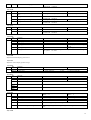
35
PIF PLL
-
36
37
38
IF Vcc 5V
Reg Fil
AU monitor out1
-
39
40
41
42
43
44
45
IF AGC
IF GND
IF in
IF in
RF AGC
Black Det
SVM/Monitor
In
In
46
47
48
49
50
51
APC Filter
YC Vcc 5V
H/L out
DVCC
R out
G out
1
2
Pin name
EyeCare or X-ray
-
Out
Out
Input terminal for Audio1 signal 1
Input terminal for Chroma or Video signal
Input terminal for Video signal
Terminal to be connected capacitor for ALC(Audio Level Control)
Input terminal for Video signal.(Input leave = 1 Vp-p)
Input terminal for ABL/ACL control
Output terminal 1 for Audio signal
Output terminal 2 for Audio signal
Output terminal for detected PIF signal or FM radio
Output terminal for 1bit DAC, detected SIF signal or audio monitor out 2.
Input terminal for External Audio signal 1
Input terminal for H correction and 2nd SIF
Terminal to be connected capacitor for DC Negative Feedback from SIF Det
output
Terminal to be connected with loop filter for PIF PLL.This terminal voltage is
controlled PIF VCO frequency.
Vcc terminal for IF circuit. Supply 5V.
Terminal to be connected capacitor for stabilizing internal bias.
Output terminal for External Audio signal or TV audio signal selected by
BUS(Audio SW)
Terminal to be connected with IF AGC filter.
GND terminal for IF circuit.
Input terminals for IF signals.
Input terminals for IF signals.
Output terminal for RF AGC control level.
Terminal to be connected with Black Det filter for black stretch.
Output terminal for monitor function. Also output terminal for SVM signal
selectable through IIC bus.
Terminal to be connected with APC filter for chroma demodulation.
Vcc terminal for Y/C circuit
Output terminal for High or Low.
Vcc terminal for digital block
Output terminal for R signal.
Output terminal for G signal.
5
52
53
54
55
56
B out
TV DGND
up AGND
up AVDD
VIDEO1/2
Out
Out
57
58
59
60
61
62
63
64
SDA1
SCL1
50/60Hz control
PWM
MUTE
H.SYNC
REMOTE
POWER
I/O
I/O
I/O
I/O
I/O
I/O
I/O
I/O
Output terminal for B signal.
GND terminal for digital block.
GND for Oscillator circuit
Vdd for Oscillator circuit Supply 5V
TV=0,AV1=OPEN,AV2=5V
IIC-BUS SDA1
IIC-BUS SCL1
50/60Hz
PWM
MUTE
Horizontal sync signal input
Remote controller signal input
Power control & Check, On=Hi-Z(input),Off=L(output)
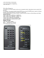
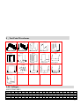
4. Remote Control Circuit Diagram and Function
A.User Remote
OPTION
56
40
45 49 4D
4C
03 07 0B 0F
1B 1F
02 06 0A 0E 12 16 1A 1E
01 05 09 0D 11
00 04 08 0C 10
14
NO.
Code
Name
TV Mode
01
02
03
04
05
06
07
08
09
10
11
12
13
14
15
16
00
01
02
03
04
05
06
07
08
09
0A
0B
0C
0D
0E
0F
0
1
2
3
4
5
6
7
8
9
CCD
-/-MENU
SYS
QV
0
1
2
3
4
5
6
7
8
9
CCD
1-Menu switch
System
Quick View
Video PP
→ ∣ P∣ ←
CUSL
CUSH
Diode
User Remote
40
BF
Pin15
6
17
18
19
20
21
22
23
24
25
26
27
28
29
30
31
10
11
12
14
16
1A
1B
1E
1F
40
45
49
4C
4D
56
MUTE
EyeCare
POWER
TV/AV
DISPLAY
V+
P+
VPService
SLEEP
CALE
ZOOM
MSG
LOCK
Mute/unmute
EyeCare
Power on/off
TV/AV
Status Recall
Volume +/Menu Item adjust(increase) and confirm
Channel +/Menu Item select
Volume -/Menu Item adjust(decrease)
Channel -/Menu Item select
Service in
Sleep
Calendar
Screen zoom/wide
Message
Lock
B.Service Remote
CUSL
CUSH
Diode
NO.
Code
Name
TV Mode
01
02
11
12
13
00
01
0A
0B
0C
G-DRV
B-DRV
MUTE3
MENU
↑
G DRIVE
B DRIVE
To set the screen into a horizontal line.
MENU
ITEM SELECT UP
14
0D
↓
ITEM SELECT DOWN
15
0E
←
Menu Item adjust(decrease)
16
0F
Menu Item adjust(increase)
21
24
25
26
29
14
17
18
19
1C
→
POWER
HPOS
OSD
M-MODE ON
VP50
Service Remote
8E
8E
Pin6,7,8,12
Power / Stand-by
60Hz HORIZONTAL PHASE
OSD POSITION ADJUSTMENT
M-MODE ON (factory produce mode)
50Hz VERTICAL PHASE
7
30
31
32
33
34
35
36
37
38
39
40
42
43
44
45
48
49
50
51
58
60
61
62
63
1D
1E
1F
20
21
22
23
24
25
26
27
29
2A
2B
2C
2F
30
31
32
39
3B
3C
3D
3E
HIT
HPS
VP60
RCUT RCUT +
GCUT GCUT +
BCUT BCUT +
HITS
VLIN
Search Down
Search Up
BRTS
D-Mode ON/OFF
POS UP
POS DOWN
Shopout
S-PVOC
BUS OFF
VSC
VLIS
AGC
TV IC ADJUST
60Hz VERTICAL AMPLITUDE
50Hz HORIZONTAL PHASE
60Hz VERTICAL PHASE
R CUT adjust(decrease)
R CUT adjust(increase)
G CUT adjust(decrease)
G CUT adjust(increase)
B CUT adjust(decrease)
B CUT adjust(increase)
50Hz VERTICAL AMPLITUDE
60Hz VERTICAL-LINEARILTY
Manual Search Down
Manual Search Up
Sub Bright
D-Mode ON/OFF switch
Position Up
Position Down
Shop-out
LOGO ADDRESS
BUS OFF
60Hz VERTICAL-S CORRECTION
50Hz VERTICAL-LINEARILTY
RF-AGC
White balance automatic adjustment
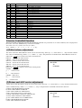
5.Service Controlled Function
The Service mode is entered by pressing the “D-MODE ON/OFF” key when the TV is in ON condition,”D” is displayed on
the screen.. Press the “POWER” key to exit Service mode.
Note:How to use user remote enter Service mode?
Press “MENU”→ “ 6” → “ 4” → “ 8” → “ 3” key
(1)White balance adjustment
The items within the White Balance mode can be accessed using “Item up” (↑ )/ “Item down” (↓ ) keys and the selected
item value is modified using “Value+” (→ )/ “Value-” (← ) keys. The parameters controlled in the White Balance menu are:
a)Press the
key to set the screen into a horizontal line
b)RCUT + : Red cut-off value increase
c)RCUT - : Red cut-off value decrease
D
d)GCUT +: Green cut-off value increase
e)GCUT -: Green cut-off value decrease
009 GDRV
f)BCUT +: Green cut-off value increase
40
g)BCUT -: Green cut-off value decrease
01000000
h)Press the
key again to return to the normal picture.
i)GDRV -: Green drive
j) → : value increase
k) ← : value decrease
l)BDRV +: Blue drive
m) → : value increase
n) : value decrease
(2)Picture and AGC service adjustment
1)The items within the Picture mode can be accessed using “Item up” (↑ )/ “Item down” (↓ ) keys and the selected item
value is modified using “Value+” (→ )/ “Value-” (← ) keys. The parameters controlled in the Picture menu are:
a) HPOS: 60Hz HORIZONTAL PHASE
b) VPOS: 60Hz VERTICAL PHASE
D
c) HIT: 60Hz VERTICAL AMPLITUDE
d) HITZ: 60Hz ZOOM VERTICAL AMPLITUDE
040 HPOS
e) HITW: 60Hz WIDE VERTICAL AMPLITUDE
15
f) VLIN: 60Hz VERTICAL-LINEARILTY
00010101
g) VSC: 60Hz VERTICAL-S CORRECTION
h) HPS: 50Hz HORIZONTAL PHASE
i) VPS: 50Hz VERTICAL PHASE
8
j) HITS: 50Hz VERTICAL AMPLITUDE
k) VLIS: 50Hz VERTICAL-LINEARILTY
l) VSS: 50Hz VERTICAL-S CORRECTION
m)AGC:Tuner AGC.
2)For Mass Production
The items of the Picture adjust mode can be accessed quickly using below service remote No.2
and No.5.
For example: If you want to adjust Vertical-SIZE ,then you push [V-SIZE] button Æpush [+] /[-]keys
to adjust Æpush [M-ON] button to exit after you adjust over.
These service remote is common remote, so some function of items is a little difference as below:
Service R/C No.2:
50HZ V-LINE: 60Hz VERTICAL-LINEARILTY
50HZ V-SIZE: 60Hz VERTICAL AMPLITUDE
50HZ V-CENT: 60Hz VERTICAL PHASE
V-SADJ: 60Hz VERTICAL-S CORRECTION
50HZ H-CENT: 60Hz HORIZONTAL PHASE
Service R/C No.5:
RFAGC: RF AGC.
OSD: OSD position adjust.
BRTC: SUB BRIGHT CENTER
Other three buttons are no used.
:
9
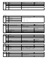
(3)Option set
1)OPT
OPT
Bit
Function
Bit7
Bit6
Bit5
Bit4
Bit3
Bit2
Bit1
Bit0
The algorithm of ASM
The algorithm of ASM
VT Down of AFT when No Signal
Fjp_bb_v_freq
Fjp_digital_aft
V MUTE V-MuteOn/Off when CH changes
Fvmute_type During POS change
Fjp_menu_background
Status “ 0”
ASM doesn't judge IFLOCK with case 4
ASM doesn't judge AFT area with case 4
no use
C_BB_V_FREQ_313H
no use
Off
Y-MUTE
no use
Status “ 1”
ASM judge IF LOCK with case 4
ASM judge AFT area with case 4
use
C_BB_V_FREQ_312_5H
use
On
RGB-CUT Off DC
use
Status “ 0”
no use
no use
normal
no use
AV status memory
multi color system
p3
no use
Status “ 1”
use
use
inverse
use
only TV while power on
only358ntsc
p2
use
Status “ 1”
add special process for mute
refresh the registers of FS tuner at
the interval of 256ms
1S delay power on
must use remote control to open
TV
use
use
mute
35%(set bit6 of register 0x1e of
2in1 to 1)
2)OPT1
OPT1
Bit
Function
Bit7
Bit6
Bit5
Bit4
Bit3
Bit2
Bit1
Bit0
Fjp_calendar
Fjp_eyecare
Fjp_tint
Fjp_screen
Fjp_rf_pwron
Fjp_ntsc358
Fjp_uhf
Fjp_message
3)OPT2
OPT2
Bit
Function
Bit7
Bit6
Fjp_mute_process
Fjp_refresh_tuner
Status “ 0”
no special process
no refresh
Bit5
Bit4
Fjp_pwr_delay
Fjp_power_option
nouse
stand by status
Bit3
Bit2
Bit1
Bit0
Fjp_woofer
Fjp_ta1343n
Fav_chg_mute
Fslice_level(use to control the seventh
bitof2in1 0x1e register)
no use
no use
not mute
40%( set bit6 of register 0x1e of 2in1 to
0)
4)OPT3
OPT3
Bit
Function
Bit7
Bit6
No use
PP mode option
Status “ 0”
VID
mode
Standard
Dynamic
Mild
Movie
Nature
Status “ 1”
Contrast
Brightness
Sharpness
Colour
100
80
50
60
75
50
75
40
40
50
50
60
30
50
40
50
50
40
50
45
EK
mode
Standard
Dynamic
Mild
Movie
Nature
Contrast
Brightness
Sharpness
Colour
50
100
40
100
75
50
75
50
40
50
50
60
30
50
40
50
50
50
50
50
Bit5
Fjp_pos_av_option
no use
Bit4
Bit3
Bit2
Bit1
Fjp_mute_exmute
Fjp_50_60hz_control
Fjp_panel_power
Exmute while pos
change
Extend mode attenuation
no use
no use
panel power key is permitted while panel lock
exmute output
using local pos key to enter AV while no local
TV/AV key
use
use
panel power key is forbidden while panel lock
no exmute
according to effect1
-5db
Bit0
5)AOPT
AOPT
Bit
Function
Status “ 0”
Status “ 1”
Bit7-6
Bit5
No use
Fjp_dvd_output
following AV1
following AV2(pin56 or pin61)
10
Bit4
Bit3
Bit2
Bit1
Bit0
Fjp_av_stereo
Fjp_fm
Fjp_video2
Fjp_dvd
Fjp_S-video
AV mono
no FM
no VIDEO2
no DVD
no S-video
AV stereo
use FM
use VIDEO2
use DVD
use S-video
Bit
Function
Bit7
Bit6
Bit5-4
Bit3
Bit2
Bit1-0
No use
ALS SW for ta1343
ALS start point
No use
Input attenuation
No use
Status “ 0”
Status “ 1”
This bit must be zero
off
on
00:220[mv] 01:380[mv] 10:525[mv] 11:770[mv]
This bit must be zero
0dB
-5dB
Bit
Function
Bit7
Bit6
Bit5-4
Bit3
Bit2-0
Bass boost
No use
Woofer LPF
No use
Surround effect level
6)EFF1
EFF1
7)EFF2
EFF2
Status “ 0”
Status “ 1”
off
on
This bit must be zero
on
00:100[hz] 01:125[hz] 10:170[hz] 11:210[hz]
000:off
001:1
…..
111:7
8)CCOR
CCOR
Bit
Function
Bit7
Bit6
Bit5-4
Bit3-0
No use
Italic enable specification register
No use
Set menu character’s color
Status “ 0”
Status “ 1”
No use
normal
italic
No use
0:BLACK 1:BLUE
2:GREEN 3:CYAN 4:RED 5: MAGENDA
6:YELLOW 7:WHITE 8:BLACK 9: DARK BLUE
10:DARK GREEN and so on
9)TCOR
TCOR
Bit
Function
Bit7
Bit6
Bit5
Bit4
Bit3-0
No use
Italic enable specification register
Underline enable specification register
No use
Set menu top character’s color
Status “ 0”
Status “ 1”
No use
normal
italic
normal
underline
No use
0:BLACK 1:BLUE
2:GREEN 3:CYAN 4:RED 5: MAGENDA
6:YELLOW 7:WHITE 8:BLACK 9: DARK BLUE
10:DARK GREEN and so on
10)SCOR
SCOR
Bit
Function
Bit7
Bit6
Bit5-4
Bit3-0
No use
Italic enable specification register
No use
Set menu selected character’s color
Status “ 0”
No use
0:normal
1: italic
No use
0:BLACK 1:BLUE
2:GREEN
6:YELLOW 7:WHITE
Status “ 1”
3:CYAN 4:RED
5: MAGENDA
11)ACOR
ACOR
Bit
Function
Bit7
Transparency enable register for the menu
area
Color select for the menu area
Bit6-4
Bit3
Transparency enable register for the
highlight menu area
Status “ 0”
not assign half transparency
Status “ 1”
assign half transparency
0:BLACK 1:BLUE
2:GREEN
3:CYAN 4:RED 5: MAGENDA
6:YELLOW 7:WHITE
not assign half transparency
assign half transparency
11
Bit2-0
Color select for the highlight menu area
0:BLACK 1:BLUE
2:GREEN
6:YELLOW 7:WHITE
Bit
Function
Bit7
Status “ 0”
not assign half transparency
Bit6-4
Transparency enable register for calendar
area
Background color for the calendar area
Bit3
Bit2-0
Transparency enable register for week area
Background color for the week area
3:CYAN 4:RED
5: MAGENDA
12)CALB
CALB
Status “ 1”
assign half transparency
0:BLACK 1:BLUE 2:GREEN3:CYAN 4:RED 5: MAGENDA
6:YELLOW 7:WHITE
not assign half transparency
assign half transparency
0:BLACK
1:BLUE
2:GREEN3:CYAN
4:RED
5: MAGENDA
6:YELLOW 7:WHITE
13)CALC
CALB
Bit
Function
Bit7-3
Bit2-0
No use
Status “ 0”
Status “ 1”
Set the character color of calendar
0:BLACK 1:BLUE 2:GREEN3:CYAN 4:RED 5: MAGENDA
6:YELLOW 7:WHITE
Bit
Function
Status “ 0”
Bit7
Bit6
Bit5
Bit4
No use
Fjp_logv_plus
Fjp_logo_size
Fjp_logo_tvon
up
middle
no use
Bit3
Bit2-0
Fjp_logo_nosignal
Set logo color
14)LOGO
LOGO
Status “ 1”
no use
000: black 001:blue
110: yellow 111: white
down
large
logo display while switching on
TV set
logo display while no signal
010: green 011: cyan 100: red 101: magenda
15)LOGH
adjust the horizontal display position of lo
16)LOGV
adjust the vertical display position of logo
17UVBK
LOGO
Bit
Function
Bit7-4
Bit3-0
U BLK ADJ
V BLK ADJ
Status “ 0”
0: -22mV, Input DC
0: -22mV, Input DC
8: 0mV
8: 0mV
Status “ 1”
F: 19mV, 2.75mV/dev
F: 19mV, 2.75mV/dev
18) ABCL
ABCL
Bit
Function
Bit7
Bit6
Bit5-4
Fjp_rf_agc
Y Peak Limiter
ACL STATR POINT
Status “ 0”
IF isn't mute while AV
Y peak limiter on,105IRE
0:0V
01:-0.2V
10:-0.3V
Bit3
Bit2
Bit1
Bit0
ABL START POINT
00: 0V
10: -0.30V
ABL GAIN
00: -0.2V
Bit
Function
Bit7
Bit6
Bit5
Bit4
Bit3-2
C Trap Q _Y
Blanking switch
No use
Black stretch SW
Y GAMMA
Status “ 0”
Low
H,V blanking on
Status “ 1”
High
H,V blanking off
Off
00:off
On
10:68 IRE
Bit1-0
Black stretch start point and gain
01: -0.2V
01: -0.35V
10: -0.5V
Status “ 1”
IF mute while AV
Y peak limiter off
11:-1.0V ACL OFF
11: -0.4V
11: -0.65V
19)DCBS
DCBS
01:Y gamma point 78IRE,gain-6db
11:58 IRE
00:30IRE,gain high 01:40IRE,gain high 10:50IRE,gain low 11:75IRE,gain
low
20)CLTM
12
CLTM
Bit
Function
Bit7
Bit6
Bit5
Bit4-3
P/N ID
Killer off
N COMB
Demodulation Phase
Bit2-0
Y Delay Time
000:0ns 001: 40ns 010: 80ns
110: 240ns 111: 280ns
Bit
Function
Bit7-6
AFC GAIN (TV mode, weak signal and
Nois_Bit4=0)
AFC GAIN (TV mode, strong signal and
Nois_Bit4=0)
AFC GAIN (AV mode)
AFC GAIN (TV mode, and Nois_Bit4=1)
Status “ 0”
Data Description Blanking
Blanking period Picture period
00:
1
1
01:
4/3
1/3
10:
2
1
11: OFF
OFF
Status “ 0”
PAL/NTSC killer sensitivity, Normal
Normal
Off
00:PAL
01:NTSC1 10:NTSC2
Status “ 1”
LOW
Always killer off
Color comb filter for NTSC. On
11:DVD
011: 120ns 100: 160ns
101: 200ns
21)HAFC
CLTM
Bit5-4
Bit3-2
Bit1-0
Status “ 1”
22)FLG0
FLG0
Bit
Function
Bit7
Bit6-5
vco adjust when position select
Select f0 of chroma BPF
Bit4
BPF-SW
Bit3
Fvcd_spot_killer
Bit2
Bit1
Bit0
Nyquist Buzz cancel
No use
Over mode
Status “ 0”
Status “ 1”
enable
disable
0: BPF (AV) 01: TOF1(F0=5MHZ)RF 10: TOF2(F0=6MHZ)RF
11: TOF3(F0=7MHZ)RF
Normal, CVBS signal passes along BPF
By pass, CVBS signal doesn't
pass along BPF
off
If BB=1, RGB out is 110 IRE
Nyquist Buzz cancel
off
Normal
PIF over modulation switch on
Status “ 0”
ABCL active for OSD
Status “ 1”
inactive
23)FLG1
FLG1
Bit
Function
Bit7
Bit6
Bit5-4
OSD ABL
No use (don't use it)
OSD CONTRAST
Bit3
Horizontal side blanking
OFF
Bit2
Bit1
Bit0
Fvcd_fm_band
V ramp bias
CW SW
Normal
power from Y/C VCC
Off
On, 92% (FBP BLK off, then
internal BLK only)
Wide
power from IC
On
Bit
Function
Status “ 0”
Status “ 1”
Bit7-5
Bit4
Bit3-2
No use
MON/SVM
SVM delay
Pin45 SVM out
00:off
01:-120ns
Bit1-0
SVM gain
00: -7dB
00: 95 IRE
01: 60 IRE
10: 70 IRE
11: 80 IRE
24)SVM
SVM
10:-100ns
01:-1Db 10:+5dB
Monitor out
11:-80ns
11:+11dB
25)UCOM
UCOM
Bit
Function
Bit7-5
Bit4-3
No use
C APC DATA
Bit2
Set chroma APC
Status “ 0”
Status “ 1”
00: data 1-normal for black &white &NTSC 01: Data 2 10: Data 3 for
PAL 11: the same as 10
disable
enable use Bit 3,4 data
13
Bit1-0
Internal ADC
00:GND
01: R output
10: B output 11: Monitor RF AGC via ADC
26)SSM
SSM
Bit
Function
Bit7-6
Bit5-4
No use
S Trap Frequency response Control HP/LP
For M
S Trap Q. for M
S Trap Group Delay Control for M
00: Q = 3
00:off
Bit
Function
Status “ 0”
Status “ 1”
Bit7-3
Bit2
Bit1
Bit0
No use
H sync judgement
Fvcd_sync_separation level
Sync slice level for weak signal
BUS
40%
normal
TC3
50%
low
Bit3-2
Bit1-0
Status “ 0”
Status “ 1”
00:OFF 01:1dB HPF 10:-3dB LPF 11:-2dB LPF
01:Q = 5 10:Q = 7 (Recommended) 11:Q = 9
01:60ns 10:90ns
11:120ns
27)SYNC
SYNC
28)SYNB
SYNB
(Sync
detecti
on
setting
for BB
On)
Bit
Function
Bit7
Bit6
Bit5
No use
Reg.19H bit7 SY-DET-1 for 889x
Reg.19H bit6 SY-DET-4 for 889x
Bit4
Bit3
Bit2
Bit1-0
Reg.19H bit5 0 for 889x
Reg.21H bit1 SY-DET-2 for 889x
Reg.21H bit0 SY-DET-3 for 889x
Sel sync check mode for BB on
Status “ 0”
Status “ 1”
Select the input IF signal level of Sync Lock detection. 00010: 0dB
00011: 0dB 10010: 0dB 10011: 0dB 10001:-4dB 10000:-8dB weak signal
others:Do not use
00:checking H-LOCK-1 flag(bit3 of r0) 01:checking
flag(bit4 of r1) 1x:checking VLOCK flag (bit7 of r1)
H-LOCK-2
29)SYBF
SYNB
(Sync
detecti
on
setting
for BB
Off)
Bit
Function
Bit7
Bit6
Bit5
No use
Reg.19H bit7 SY-DET-1 for 889x
Reg.19H bit6 SY-DET-4 for 889x
Bit4
Bit3
Bit2
Bit1-0
Reg.19H bit5 0 for 889x
Reg.21H bit1 SY-DET-2 for 889x
Reg.21H bit0 SY-DET-3 for 889x
Sel sync check mode for BB oFF
Status “ 0”
Status “ 1”
Select the input IF signal level of Sync Lock detection. 00010: 0dB
00011: 0dB 10010: 0dB 10011: 0dB 10001:-4dB 10000:-8dB weak signal
others:Do not use
00:checking H-LOCK-1 flag(bit3 of r0)
flag(bit4 of r1)
1x:checking VLOCK flag (bit7 of r1)
01:checking
H-LOCK-2
30)SYSR
SYNB
(Sync
detect
ion
settin
g for
searc
h/tuni
ng)
Bit
Function
Bit7
Bit6
Bit5
No use
Reg.19H bit7 SY-DET-1 for 889x
Reg.19H bit6 SY-DET-4 for 889x
Bit4
Bit3
Bit2
Bit1-0
Reg.19H bit5 0 for 889x
Reg.21H bit1 SY-DET-2 for 889x
Reg.21H bit0 SY-DET-3 for 889x
Sel sync check mode for search/tuning
Status “ 0”
Status “ 1”
Select the input IF signal level of Sync Lock detection. 00010: 0dB
00011: 0dB 10010: 0dB 10011: 0dB 10001:-4dB 10000:-8dB weak signal
others:Do not use
00:checking H-LOCK-1 flag(bit3 of r0)
flag(bit4 of r1)
1x:checking VLOCK flag (bit7 of r1)
01:checking
H-LOCK-2
31)VCD0
VCDO
Bit
Function
Bit7-6
Bit5-4
Audio Monitor Out
C Trap MD
Bit3
Bit2
Bit1
Bit0
Halftone Gain
U/V Switch
Sharpness f0 frequency
Sync. skew switch
Status “ 0”
Status “ 1”
00:depend on Audio SW 01:TV 1X:mute
00: interlocking video SW 01: as 00 10: not interlocking C-trap off 11: not
interlock C-trap on
Main:OSD 30%: 70%
Main:OSD 50%: 50%
Cb/Cr, Cr input(#21)gain up,+3Db
U/V
2.75MHz
4MHz
OFF
sync skew detection on
14
32)VCD1
VCD1
Bit
Function
Status “ 0”
Bit7-4
Bit3-2
Bit1-0
No use
PIF detected output level trimming
FM BPF
00: 1.05Vp-p 01:do not use 10: 2.2Vp-p 11:do not use
00: internal BPF mode 01: not use10: not use 11: external BPF mode
Status “ 1”
33)CATVM
00=STD
01=IRC
02=HRC
34)LOGO address
280-28F
290-29F
logo display while switching on TV set
logo display while no signal
Use No.5 Service Remote press“ S-PVOC” key into LOGO address, then use No.1 Service Remote press“ ↑ /↓ ” key to select LOGO
address and press “ ← /→ ”
alphabet A
B
data
41
42
key to adjustment data.
C
D
E
43
44
45
F
46
G
47
H
48
I
49
J
4A
K
4B
L
4C
M
4D
alphabet
data
N
4E
O
4F
P
50
Q
51
R
52
S
53
T
54
U
55
V
56
W
57
X
58
Y
59
Z
5A
number
data
0
30
1
31
2
32
3
33
4
34
5
35
6
36
7
37
8
38
9
39
Spacing
20
End
00
35) PVHH/PVHL/PUHH/PUHL
FS Tuner band set
For example: Some Tuner band specification is:
L:55.25-127.25 MHz(C2-B)/M:133.25-361.25 MHz(C - W+11)/H:367.25-801.25 MHz(W+13 –C69)
PVHH/PVHL
{[(127.25+133.25)÷2+45.75]x16-48} =2768(algorism), change to hex is 0AD0,so PVHH=0A ,PVHL=D0
PUHH/PUHL
{[(361.25+367.25)÷2+45.75]x16-48}=6512(algorism), change to hex is 1970,so PVHH=19 ,PVHL=70
PVHH=OA
PVHL=D0
PUHH=19
PUHL=70
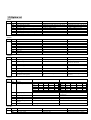
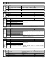
6. Service and Design Data
21” UTI T008 BUS DATE
NO.
006
007
008
T008
ITEM
RCUT
GCUT
BCUT
DATA
20
20
20
21”
REMARK
R CUT OFF
G CUT OFF
B CUT OFF
SAMSUNG
ITEM
069 TREC
070 BALC
071 WOFC
009
010
011
012
013
014
015
016
017
018
019
020
021
022
023
024
025
026
027
028
029
030
GDRV
BDRV
CNTX
BRTS
BRTC
COLC
TNTC
COLP
SCNT
CNTC
CNTN
BRTX
BRTN
COLX
COLN
TNTX
TNTN
ST3
SV3
ST4
SV4
SVD
40
40
7F
00
48
40
40
00
0A
58
00
35
25
35
0B
35
28
20
25
18
25
25
G DRIVE
B DRIVE
SUB CONTRAST MAX
SUB BRIGHNESS
SUB BRIGHT CENTER
SUB COLOR for NTSC
SUB TINT CENTER
SUB COLOR for PAL
SUB CONTRAST
SUB CONTRAST CENTER
SUB CONTRAST MIN
SUB BRIGHT MAX
SUB BRIGHT MIN
SUB COLOR MAX
SUB COLOR MIN
SUB TINT MAX
SUB TINT MIN
TV—3.58 SHARP
AV—3.58 SHARP
TV—4.43 SHARP
AV—4.43 SHARP
DVD SHARP CENTER
072
073
074
075
076
077
078
079
080
081
082
083
084
085
086
087
088
089
090
091
092
093
DATA
40
3F
39
REMARK
TREBLE CENTER VALUE
BALANCE CENTER VALUE
WOFFER CENTER VALUE
BASX
TREX
WOFX
72
72
72
EFF1
EFF2
FLG0
FLG1
SVM
VBLK
VCEN
UCOM
PYNX
PYNN
PYXS
PYNS
AUSTP
STM
SSM
SYNC
SYBN
SYBF
SYSR
40
17
44
20
10
00
27
10
33
11
22
1E
04
07
07
02
44
44
44
BASS MAX VALUE
TREBLE CENTER VALUE
WOFFER CENTER VALUE
SOUND EFFECT1
SOUND EFFECT2
FLAGS
FLAGS
SVM
V BLK Start/Stop
V CENTERING
Miciom Control
NORMAL H.SYNC MAX
NORMAL H.SYNC MIN
SEARCH H.SYNC MAX
SEARCH H.SYNC MIN
AUDIO STEP
S Trap f0 For M
S Select For M
SYNC
Sync detection setting for BB On
Sync detection setting for BB Off
Sync detection setting for search/tuning
15
031
ASSH
ASYMMETRY SHARP
07
032
033
034
035
036
037
038
SHPX
SHPN
UVBK
ABCL
DCBS
CLTM
CLVO
35
10
88
E7
17
B7
B7
039
CLVD
98
SUB SHARP MAX
SUB SHARP MIN
U/V BLK ADJ
ABL SYSTEM
A part of Video data in detail
The data when TV mode&SOUND SYS=M
The data when YUV mode&SOUND
SYS!=M
The data when YUV mode&SOUND SYS=M
040
041
HPOS
VPOS
OC
01
60Hz HORIZONTAL PHASE
60Hz VERTICAL PHASE
042
043
044
HIT
HITZ
HITW
24
09
12
60Hz VERTICAL AMPLITUDE
Zoom VERTICAL AMPLITUDE
Wide VERTICAL AMPLITUDE
045
VLIN
12
60Hz VERTICAL-LINEARILTY
046
047
048
VSC
HBOW
HPAR
0E
04
04
60Hz VERTICAL-S CORRECTION
H. BOW
H. PAR
05
00
00
00
00
OSD Vertical position for 60Hz
50Hz HORIZONTAL PHASE
50Hz VERTICAL PHASE
50Hz VERTICAL AMPLITUDE
50Hz VERTICAL-LINEARILTY
054
055
056
057
VSS
OV50
RAGC
HAFC
00
00
25
86
50Hz VERTICAL-S CORRECTION
OSD Vertical position for 50Hz
RF AGC
AFC GAIN
058
NOIS
0F
NOISE
059
NDTC
1F
NOISE DET count (Weak -> Normal)
060
V1
09
TV VOLUME 1%
061
062
063
V25
V50
V100
3D
57
75
TV VOLUME 25%
TV VOLUME 50%
064
065
066
AV50
AV100
ATTV
5A
79
70
ATAV
068
BASC
40
BBCT
04
VCD0
VCD1
CCOR
TCOR
SCOR
ACOR
CALB
0E
08
43
65
06
88
FD
Blue back hysteresis counter (BUS H sync
detection)
VCD0 data
VCD1 data
Set menu character’s color
Set menu top character’s color
Set menu selected character’s color
Set menu’s background color
Menu color option
00
SET CALENDAR BACKGROUND COLOR
30
59
CCD OSD POSITION ADJUSTMENT
CCD OSD WIDTH
51
10
40
OSD WIDTH
OSD POSITION ADJUSTMENT
To set remote controller's custom code(low
byte)
To set remote controller's custom code(high
byte)
FS tuner address
Be used to adjust the xray protect voltage
104
105
106
CALC
CCD OSD
CCD
OSDF
OSDF
OSD
107
CUSL
108
109
110
CUSH
FSAD
VPL
111
112
113
114
115
VADJ
SADJ
LOGH
LOGV
LOGO
BF
OV60
HPS
VPS
HITS
VLIS
70
102
103
049
050
051
052
053
067
094
095
096
097
098
099
100
101
116
117
118
119
ERAS
CATVM
WTON
WOTF
120
PVHH
121
PVHL
122
PUHH
123
124
125
PUHL
SOSP
HPSD
AV VOLUME 50%
AV VOLUME 100%
To set the register of audio ATT while using
ta1343n at TV or FM mode
To set the register of audio ATT while using
ta1343n at VIDEO or DVD mode
001
002
OTP
OTP1
003
OTP2
004
OTP3
BASS CENTER VALUE
005
AOTP
C0
C5
00
07
00
0F
45
A3
00
7D
EF
0A
Be used to adjust the base input voltage of
eyecare
Be used to adjust the check speed of eyecare
LOGO HORIZONTAL POSITION
LOGO VERTICAL POSITION
LOGO select
Be used to adjust the time of thermal resistance
control
CATV select
10
03
Turn on delay set
Turn off delay set
Be used to set the start frequency of VHFH
band of FS tuner(high byte)
Be used to set the start frequency of VHFH
band of FS tuner(low byte)
Be used to set the start frequency of UHF band
of FS tuner(high byte)
Be used to set the start frequency of UHF band
of FS tuner(low byte)
Position OSD adjustment
DVD HORIZONTAL PHASE
17
9D
B2
OPTION
OPTION1
OPTION2
53
OPTION3
14
AV OPTION
D0
19
D0
TV VOLUME 100%
7.ICs Functional Description
TDA9302B
PIN
1
2
3
4
TDA7267
PIN
1
2
3
4
5
6
Function : Vertical Output
PIN CONNECTIONS
Input
Vcc
PUMP UP OUT
GND
Function : Audio Output
PIN CONNECTIONS
NC
NC
SUR/MUTING
INPUT(-)
INPUT
GND
PIN
5
6
7
PIN CONNECTIONS
V. OUT
Output Stage Vcc
NON. INV. IN
PIN
7
8
9
10
11
PIN CONNECTIONS
NC
OUTPUT
Vcc
NC
NC
16
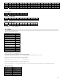
8.Test Point Waveforms
2Vpp
1Vpp
H
H
A8891 PIN30
A8891 PIN26
95Vpp
95Vpp
3.8Vpp
3.8Vpp
H
3.8Vpp
H
A8891 PIN51
A8891 PIN50
H
A8891 PIN52
7Vpp
95Vpp
5Vpp
H
H
CRT KG
H
CRT KR
4.5Vpp
H
H
CRT KB
A8891 PIN13
0.7Vpp
1.3Vpp
A8891 PIN16
H
V411 C
V444 B
A8891 PIN6
23Vpp
1000Vpp
H
V
A8891 PIN12
H
HEATER
75Vpp
H
V444 C
9. IC Voltages
A8893CPNG-6RE1
Pin
Voltage
1
2.7
2
0.1
3
5.1
4
0.0
5
5.1
6
2.3
7
2.1
8
0.0
9
5.1
10
0.0
11
0.0
12
1.1
13
2.1
14
5.5
15
4.1
16
4.9
17
7.9
18
0.0
19
1.9
Pin
Voltage
20
1.9
21
2.0
22
3.9
23
2.4
24
2.5
25
0.7
26
2.7
27
4.4
28
3.1
29
3.2
30
3.0
31
3.2
32
3.9
33
2.9
34
2.2
35
2.4
36
5.0
37
2.1
38
3.1
17
Pin
Pin
39
3.0
40
0.0
41
2.0
42
2.0
43
2.0
44
1.9
45
2.8
46
2.3
47
5.0
48
2.0
49
3.3
Pin
Voltage
58
5.1
59
5.1
60
5.1
61
0.1
62
0.6
63
5.1
64
3.4
2
26.5
3
1.5
4
0.0
5
13.2
6
26.8
7
3.0
4
1.7
5
1.7
6
0.0
7
0.0
8
8.9
9
19.6
10
0.0
11
0.0
4
5
6
7
8
9
10
11
50
2.6
51
2.6
52
2.6
53
0.0
53
0.0
55
5.1
56
0.0
57
5.1
STV9302B
Pin
Voltage
1
3.0
TDA7253(Mono)
Pin
Voltage
1
0.0
2
0.0
3
11.5
TDA7263(Stereo)
Pin
Voltage
1
AC supply :
2
3
110V 50/60Hz
10. Other
1)Binary code change to hex
Binary code
0 0 0 0
0 0 0 1
0 0 1 0
0 0 1 1
0 1 0 0
0 1 0 1
0 1 1 0
0 1 1 1
1 0 0 0
1 0 0 1
1 0 1 0
1 0 1 1
1 1 0 0
1 1 0 1
1 1 1 0
1 1 1 1
Hex
0
1
2
3
4
5
6
7
8
9
A
B
C
D
E
F
2) Some skills of factory adjustment:
a)How to use Service Remote enter service mode?
Pressing the “D MODE ON/OFF” key. Press “D MODE ON/OFF” key again to exit service mode.
b)How to use User remote enter Service mode?
Press “MENU”→ “ 6” → “ 4” → “ 8” → “ 3” key(within 6s).
c)How to unlock V-CHIP if you forgot password?
Press V-” key on the set to“ 00” keep then press MENU” key on the User Remote. Into V-CHIP menu, set V-CHIP password again.
3)Keyboard input:
Key In
0.0-0.3V
0.3-1.0V
1.0-1.7V
1.7-2.4V
2.4-3.1V
3.1-3.8V
3.8-4.5V
Key Pressed
POWER
Program+
ProgramVolume+
VolumeTV/AV
Menu
18
0
0
0
28V