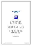
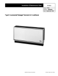
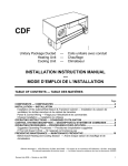
1
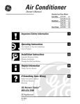
EMS MOVES FREIGHT DOORS LIKE NO OTHER EMS exclusive closed-loop control system constantly monitors and adjusts the performance of your freight elevator doors. The result is smooth door and gate operation… EVERY TIME. Modernize all existing EMS, Courion, Peelle, & Security power door & gate installations. Upgrade includes new Door & Gate Controller and Door & Gate Tracking Sensors. Replaces existing limit switches. No changes to door & gate motors or door interlocks required. Benefits… Elimination of wear and tear on high-maintenance parts caused by slamming doors. No limit switches to adjust Quiet operation … every time! Reduction of downtime and costly maintenance calls Easy set-up system, including automatic adjustment Flexibility… ideal for new installations or modernization of most existing equipment (Both EMS designed doors and gates, and those of our competitors) Silent cam operation … no cam bounce and no dampening devices that can fail Adjustable gate closing speed for improved safety Elimination of costly duplication … one control system operates front and rear same level openings Most advanced freight door control system in the industry (control photo here) GUIDE TO QUALITY FREIGHT PRODUCTS Section 1: Quality Benefits Section 2: Hoistway Doors Section 3: Car Door/Gate Section 4: Cab Enclosures Section 5: Control Section 6: Hoistway Construction and Framing Section 7: Technical Data Section 8: Door Space Requirement Drawings Section 9: Gate Space Requirement Drawings Section 10: Door & Gate Specifications St. Louis, MO 2 3 7 9 10 11 12 13 22 27 800-489-4889 1 Section 1: Quality Benefits o o o o Complete installation & Service manuals accompanies each shipment. All products are continuously evaluated & engineered for ease of installation and longevity of service. Technical assistance is second to none when… On time shipments are made when you want them. You specify the ship date, and EMS will call you 24-48 hours prior to that date to verify project schedule, address, and contact person for 24 hr delivery notice. o APPLICATIONS • Department Stores, Sports Arenas, Hotels, Light to Medium Commercial, Light Industrial Normally these elevators are used for hand truck loading that places elevator in loading Class A. The elevator is not subjected to high moisture or extremely dusty conditions. The electrical devices in the hoistway and machine room (for power doors) are NEMA 1. Freight handlers will be the only passengers allowed on the freight elevator. • Manufacturing Plants, Warehousing Facilities, Medium to Heavy Industrial These elevator doors are designed to withstand the rugged duty of industrial fork lifts driving onto and off of the elevator with a loading of Class C1, C2 or C3 (see Technical Data). The trucking sills are reinforced with structural steel to withstand elevator capacities of up to 60,000 lbs. EMS closed loop control will reopen any door that might bounce close during trucking across the landing door. The incidental dust that may occur from the industrial facility will not require any special Nema classification for the electrical devices. If the facility has excessive dust generated by the manufacturing process, request NEMA 12 devices. If the elevator is in a high moisture area of the facility or there is the need to periodically wash down the hoistway, request NEMA 4 devices. • Food Processing Facilities, Water Treatment Plants, Open Elevator Shafts, Corrosive Environment Facilities These elevators are normally Class C1 or C2 for industrial forklift use. The landing doors and car door/gate are often constructed of stainless steel to resist the harsh environment. The electrical devices are rated NEMA 4X to protect against water entry and to resist corrosion. • Loading Docks, Rooftop Landings, Exterior Openings We recommend that any landing door that opens to the exterior of the building be equipped with weatherstrip to protect the hoistway from exterior temperatures and moisture. The landing doors should have a factory or field applied rust inhibitive enamel finish. • Chemical Plants, Paint or Adhesive Facilities, Oil Refineries The elevator may fall under the light industrial or heavy industrial category. If the elevator is in an area that can be exposed to explosive gases or dust, the electrical devices will need to have the appropriate rating for the environment in which they will be operating. A NEMA 7 rating applies to explosive gases, and a NEMA 9 rating applies to explosive dust. The facility engineer will normally provide the classification for the elevator which will include the Class, Group and Division for the explosive environment. St. Louis, MO 800-489-4889 2 Section 2: Hoistway Doors o Hoistway Door Types • Vertical Bi-Parting Door panels are constructed with an upper and lower panel where the lower panel slides down between the building sill and car platform. The top of the lower door is used support trucking loads onto the elevator. The upper panel simultaneously travels upward above the opening to provide a clear opening. The two panels counterbalance each other. No counterweight is required. • Vertical Bi-Parting Pass Type Pass doors are required where the floor to floor height is not high enough to allow the upper door panel to open with out interference with the door above. See Technical Data: Space Requirements for more details. • 1/3-2/3 Bi-Parting The parting line for the door panels is 1/3 of the opening height above the sill in lieu of the centerline of the opening. The result is a shorter lower door panel that requires less room in the pit area. See Technical Data: Space Requirements for more details. • 1/3-2/3 Bi-Parting Pass Type When using the 1/3-2/3 Bi-Parting door the upper panel is larger and requires more space above the opening. When the floor to floor height is not sufficient for the larger door, the door becomes a pass door to prevent interference with the door above. See Technical Data: Space Requirements for more details. • Two Section Compounding Upper Panel Bi-Parting This arrangement is used when the overhead space is not adequate for the upper door panel to travel above the top landing opening. The upper door is constructed as two panels that pass each other as they open. See Technical Data: Space Requirements for more details. • Two Section Slide Up All Slide Up & Slide Down doors require separate counterweights. Two section slide up doors are recommended for elevators with excessive loading requirements. With both panels traveling up to open, all trucking weight is transferred directly from the building floor to the elevator platform. Projecting sills are required beyond the hoistway wall for supporting the slide up type doors. These doors can be more costly because of the additional counterweight and weight troughs that are not required on traditional bi-parting type doors. • One Section Slide Up One section slide up door is used similarly to the two section, however, the size of the opening may restrict its use due to shipping requirements. The one section slide up door requires less sill space projecting into the hoistway than the two section configuration. o UL Labeling UL ‘B’ label provided on doors up to 13’ 6” wide by 12’ 0” high. UL ‘B’ oversized label is provided on doors larger than 13’ 6” wide by 12’ 0” high up to 16’ 10” wide by 15 0 high. Doors manufactured larger than the sizes listed are built to the same stringent conditions but are beyond the capabilities of testing. St. Louis, MO 800-489-4889 3 o EMS Operating Cams • • • Retiring Cams Required on all power operated doors. On Manually operated doors, retiring cams are required to operate the lowest landing door locks where the pit is greater than 5’0”. Retiring cams are also required on elevators with a rise greater than 15’0”. (Note: Requirements vary with some local codes) • Stationary Cams - May be used on manually operated doors that do not require retiring cams. o Operation • Power Operated Doors are recommended for doors with an opening size greater that 10’ by 10’ or when elevator is intended for industrial truck use. • Manually Operated Doors. All EMS manual landing doors are upgradeable to power operation without the costly need for complete replacement. o Features • Product Construction o o • Flush steel plate construction utilizing angle reinforcing ribs welded to a 12 ga. carbon steel roomside sheet. Perimeter frame is constructed using angle and channel assemblies. Door Tracks are formed carbon steel “J” section of 3/16” thick material. Mounting holes are provided for both track mounting to jamb channels and at all hardware mounting locations. Standard Equipment o o o o o o o o o o o o o St. Louis, MO Bi-Parting vertical operating doors that are equipped with relating chains to synchronize operation. Bi-Parting doors are equipped with a truckable sill on the top of the lower door panel. All doors are equipped with a vision glass unless specified otherwise. The leading edge of the upper door panel is equipped with a non-shearing, non-crushing UL tested and approved astragal assembly. Interlocks: Interlocks or Lock and Contacts are provided as required by code. Locks are used to lock the upper door panel in place. Relating chains are high strength leaf chain construction. Door chains are factory cut to length to help minimize installation time. Chain attachments are done with milled groove adjustable rods and connecting links. Adjustable machined groove cast guide shoes Pull straps for manual and power doors Fastener Kits packed per hardware device for ease in installation Power doors are equipped with dual operators and a position sensor to determine exact door location at all time. All electrical hardware items are minimum NEMA 1 rated. This includes door motors and position sensors on power doors. Auxiliary locking devices are provided on side opposite door interlock on doors wider than 13’6”. Manufacturers preferred track lubrication provided with each installation. 800-489-4889 4 • Optional Equipment o Electrical Devices. EMS electrical hardware meets NEMA 1 requirements. Hardware to meet all other NEMA ratings available upon request. See Technical Data: NEMA Ratings for more details. o Weatherstrip. Can be provided for exterior doors or doors at refrigerated levels to minimize airflow into the hoistway. o Sound Deadening. EMS can provide a latex bituminous coating to the shaft side of the hoistway doors. The doors receive a factory finish over the coating. This will minimize the sometime metallic sound that can occur during trucking or operation of the doors. The textured material will also help minimize noise transmitted from the hoistway to the hall or corridor. This coating is often used in hotels or office environments where noise can become an issue. o Insulated Doors. Hoistway doors are constructed to the same rigid requirements as our steel plate doors. We then apply insulating panels (R-7.5) to the shaft side of the doors and then cover with a 16 ga. steel shaft side sheet that is welded in place. o Restricted Access Locks. Electric lock to prevent operation and access to designated landings. These are used on exterior applications and secure floors of buildings. Operation can be activated by typical methods: key switch, card reader or remote security station. Lock status monitoring is available for remote signaling. The location of these locks in the hoistway are governed by and in some cases prohibited by national codes. o Thrust Angle. Used to transfer horizontal loads subjected to the lower door during trucking, back to the building structure to minimize damage to lower door panel, guide shoes and tracks. o Finishes. Many finish coatings are available. EMS standard finish is a medium gray base finish. This finish acts as a primer to most top coat finishes, or can remain as the only finish if not subjected to high moisture or UV rays. Finish enamels, epoxies, & zinc coatings can be factory applied. Color charts are available upon request or provide customer specified color and color chip. Floor designation numbers can also be applied to shaft side of hoistway doors. Typically 6” high markings. o Stainless Steel. Many construction methods exist for stainless steel hoistway doors and specific use of each particular application must be taken into account to maintain cost and provide lasting performance. Each application must be evaluated to determine whether stainless steel is being used for aesthetic value, corrosion protection, or both. St. Louis, MO Appearance. To provide a grained finish on the room side of the door, a light gauge #4 finish stainless steel fascia is applied to a standard factory finish carbon steel plate door. Other textured finishes can also be applied in this manner, such as #5WL & #6WL. Cost will vary with type of finish. Corrosion protection. Constructing freight doors with stainless steel will significantly increase the cost of the door panels. EMS has chosen a four level system to constructing doors of stainless steel with level 1 being the least expensive. Note! Appearance of the room side of the door will be a dull silver finish with weld marks and cleaning abrasions visible. o Level 1. The door frame is constructed of carbon steel with all sheet metal constructed of #300 series stainless steel. This is recommended when doors may be periodically exposed to high moisture. 800-489-4889 5 o o o St. Louis, MO Level 2. The majority of the door frame is constructed from #300 series stainless steel, including perimeter frame, sheet stiffeners, & trucking flat bar. Structural channels are zinc coated carbon steel. Miscellaneous chain arms & hitches are also zinc coated carbon steel. This method coupled with Nema 4 electrical devices are used in areas of continuous high moisture. The economics may warrant this over a level 3 construction if the doors are to sustain extreme use and their replacement will most likely occur prior to the carbon steel deterioration. Level 3. The entire door panel is completely constructed of #300 series stainless steel. All framing, sheeting, hardware and fasteners of the door panel are constructed of stainless steel. In addition to the door panel construction, the door support chains and chain hardware is constructed of stainless steel. The door guide shoes are constructed of cast bronze to reduce oxidation. This construction coupled with Nema 4X electrical devices is suitable for high moisture or corrosive areas that will require wash down duty. Level 4. The door panels, support chains & guide shoes are constructed as described in level 3 above. In addition, the door tracks, track hardware, lock hardware and miscellaneous brackets will all be constructed from #300 series stainless steel. Any level of corrosion protection can be coupled with the grained stainless steel laminate to achieve superior corrosion resistance without compromising room side appearance. 800-489-4889 6 Section 3: Car Door/Gate o Car Door/Gate Types • Single Section A single section gate is used when there is adequate overhead in the shaft for the complete gate panel to open. It is the most cost effective application. • Two Section Compound This product is provided on elevators when the available overhead is less than that required for the opening height dimension plus the panel height. Normally the lower gate panel is slightly larger than half the opening height and the upper panel height varies depending on opening height. This is the most economical of the two section gate types. • Two Section Ratio Driven (Differential) This is the more expensive two section gate arrangement. Both upper and lower gate panels are the same size, which allows its use on elevators where available overhead space is a minimum. Both panels are independently counterweighted. The counterweight trough requires more space on the front of the car platform and cab wainscot must be set further back than more standard gate arrangements. o Operation • • Power Gate Manual Gate o Features • Product Construction o o • EMS single section car gate is constructed of 1-1/2” square, #10 gauge wire mesh, set in a perimeter structural angle frame (two section gates will use mesh that rejects a ½” ball to comply with national codes). Angle and flat bar ribs are utilized to provide reinforcing across the body of the gate panel. The car gate will close off the entire width of the entrance cab to a height 6’-0”. Gate Tracks. Formed steel “C” section of 3/16” thick material. Mounting slots are provided for track mounting to assist in setting the track gauge. Standard Equipment o o o o o o o St. Louis, MO Single section mesh gate that slides up to open. Car gate is equipped with support chains that connect the counterbalance weight. Counterbalance weight utilizes a guide system throughout its entire travel within the enclosed steel through. A contact switch is provided to interrupt the running of the car in the event the car gate is open. Support chains ride over ball bearing supported sprocket assemblies. Power operated gates are equipped with a reopening device across the bottom of the gate panel. Retiring cam and cam power unit are arranged for ease in mounting to the gate tracks. 800-489-4889 7 • Optional Equipment o Light Curtain Detection System. Multiple beam protection is provided in the path leading the car door/gate to detect an obstruction prior to contact with the car door/gate. EMS standard contact reopening device will remain on the car door/gate and will be fully functional as a redundant safety device. o Wood Bumper Guard. A hardwood bumper can be provided across the car door/gate width on elevators with both front and rear openings. It is used to help reduce damage to the closed car door/gate during loading & unloading of the elevator car. The typical bumper rail is constructed of 2” x 6” oak, and can be located from 8” off the floor to 24” off the floor, with 12” being standard. o Solid Panel Construction. The solid panel car door is fabricated similar to the steel plate door with a perimeter angle frame and angle sheet stiffeners. The smooth or sheet side of the car door is facing the inside of the car. Angles will be visible on the perimeter and corridor side of the car door. A lift bar will be provided on the car side of the car door. Typically these car doors will be made full opening height of the cab and often will require two section panel construction due to limited hoistway overhead space. o Passenger Use Package. Included is a light curtain detection system that monitors the path of the car door for possible obstructions. Restrictor locks are provided to lock the car door closed while the car is not at a selected landing. The car door supplied will be solid panel construction to close the entire car opening. Also provided is a visual and audible signaling device to alert riders that car door closing sequence is initiated. o Electrical Devices. EMS standard electrical hardware meets NEMA 1 requirements. Hardware to meet all other NEMA ratings available upon request. See Technical Data:NEMA Ratings for more details. o Stainless Steel. Like landing doors there are several construction methods for stainless steel car doors/gates. Each application must be evaluated to determine whether stainless steel being used for corrosion protection, or for aesthetic and corrosion protection purposes. St. Louis, MO Corrosion protection only. The mesh car gate is constructed entirely of #300 series stainless steel structural frame and mesh. Note! Appearance of the car gate will be a dull silver finish with weld marks and cleaning abrasions visible. Appearance & Corrosion protection. To provide a grained finish on the car side of the car door, the car door is constructed of #4 finish stainless steel. The car door will be solid panel construction and typically cover the full opening height of the cab. Other textured finishes can also be applied in this manner such as #5WL & #6WL. Cost will vary with type of finish. 800-489-4889 8 Section 4: Cab Enclosures o Product Description • • • • • • • Flush wall and ceiling construction 14ga. standard steel walls & ceiling Formed panel construction with site guards Heavy gauge tube header at cab entrance Hinged exit hatch with latch and electric contact Corner angles drilled to match gate mounting requirements Cab wall attachment to platform accessible from inside cab o Standard Equipment • • • • Recessed fluorescent light fixtures Corrosion resistant primer Cab stabilizer Fixture cutouts as required o Optional Equipment • • Heavier gauge metals up to 10ga. Available Finishes o Enamel Paint o Stainless Steel brushed (satin) finish (#4) o Textured Stainless Steel o Galvanealled Steel • Guard Railing o Hand Rails Stainless steel (3/8 x 4 raised standard) o Bumper Rails Oak wood rails (2 x 12 nominal standard) Steel Channel (8” standard) o Curbs Oak wood rails (2 x 12 nominal standard) Steel Angle (6”) • Wainscot o 4’ high side panel guard (1/8” thk. standard) • Light Fixture Guards o Car top fixture guard o Mesh lens covers • Exhaust Fan, 2 speed • Floor Plate o ¼” Aluminum floor covering o 3/8” Checkered Steel floor o 3/8” Checkered Stainless Steel floor Electrical Devices. EMS electrical hardware meets NEMA 1 requirements. Hardware to meet all other NEMA ratings are available upon request. See Technical Data:NEMA Ratings for more details. St. Louis, MO 800-489-4889 9 Section 5: Control o Product Description • • EMS Patent Pending* Closed Loop Control – Elaborate!!! EMS controller is arranged with a programmable controller processing the operating commands for the doors, gates & retiring cams. o Standard Features • • • • • • • Sequence Operation. Sequence operation for freight elevators is defined as hoistway doors opening substantially prior to car door/gate opening. In closing, the car door/gate closes substantially prior to the hoistway door closing. Momentary Pushbutton Operation. Momentary pressure on the open or close pushbutton is standard operation for all EMS freight installations. Fireman’s Operation. EMS controller is designed to provide Fireman’s Phase I, II, & Fireman’s Hold door operation in accordance with national and local codes. Hold Down Feature. This feature will re-open the doors if they should try to bounce closed during trucking across the lower door panel. This feature is standard on the EMS Closed Loop System and can be field activated by entering a simple code sequence. Automatic Opening. EMS doors are arranged to receive an input signal from the elevator control to trigger an opening sequence. Automatic Closing. With a field selectable time duration between 5 sec. and 5 minutes is available on all EMS controllers. It can be field activated by entering a simple code sequence. See EMS Service Manual for details. Supply Voltage. EMS controller can be arranged to operate on input voltages ranging between 208VAC to 600VAC, 3 phase, 50/60 cycle. Any transformers required will be supplied by EMS Group. o Optional Features • • • • • • Constant (Maintained) Pressure Close Operation. This feature is available on all EMS controllers and can be field activated by entering a simple code sequence. See EMS Service Manual for details. Remote Closing. This control feature is available and requires an input from the elevator controller. Sounder/Flasher. Nudging. Similar to passenger elevator doors, EMS doors can be arranged to deactivate the reopening devices on the car door/gate and begin to close the car door/gate at approx. 1/6 the normal closing speed. Nudging would only activate after several normal closing cycles have been initiated. Environment. EMS controller is mounted in a NEMA 1 enclosure. Enclosures to meet all other NEMA ratings are available upon request. See Technical Data: NEMA Ratings for more details. Wiring Packages: o Group 1: Is the complete package of wiring, conduit, and trough required for wiring the hoistway doors and car gate /door. A separate traveling cable is provided for the car gate/door equipment. o Group 2: EMS provides the necessary wiring and conduit to run from our landing junction box to the electrical devices for each hoistway door. Riser trough & wire are not provided. The car top junction box is provided with the necessary wire and conduit to run to the electrical devices for each car gate/door. Traveling cable is not provided. Both the landing and car top junction boxes have labeled terminals for wire connections. o Group 3: One car top junction box is provided and one landing junction box per hoistway door is provided and has labeled terminals for wire termination. St. Louis, MO 800-489-4889 10 Section 6: Hoistway Construction o Landing Door Opening Framing • • • Flush & Plumb. The landing sill, jambs, and lintel (header) must all be flush on the shaft side of the wall. No wall construction material can project beyond the shaft side face of the framing. The need for having PLUMB jambs cannot be overemphasized. Once the elevator rails are set plumb, any variation of the entrance jambs from plumb will cause variations of the running clearance between the platform and the bi-parting freight door. Code limits this running clearance between ½” to 1-¼”. When shafts contain both front and rear entrances this condition becomes critical. Frame Projection. EMS recommends to arrange the hoistway so the entrance framing projects approximately ½” into the hoistway from any wall line that has freight doors. When showing clear hoistway on layout drawings, dimension the clear hoistway between the front and rear entrance framing and show the rough hoistway being ½” larger for in-line openings, and 1” larger for elevators with both front and rear openings. This will allow for variation during construction where the distance from the jamb to back wall (or rear jamb) can be held, while the ½” frame projection can vary if need be to maintain the clear hoistway dimension. Jamb Extensions. For best results steel entrance jambs should extend above each landing to the floor beam above or for elevators with large travel between openings a minimum of ½ of the opening height above and below the opening. Having plumb & flush steel jambs to mount the full length of the door track will ease the installation and assure smooth operation of the freight doors. o Wall construction • • • • CMU (concrete block). EMS recommends that the landing door jambs continue to the floor beam above. If steel jambs do not continue to structure above, it is recommended that the blocks in the area of the door tracks be filled for use with anchors. Poured Concrete. Entrance frames are only required in the opening only. Concrete anchors will be used to secure the track above and below the opening. Note: The shaft side of the hoistway is to be flush and plumb. We recommend having the entrance framing project ½” into the hoistway to allow for swelling or inconsistencies of concrete without interfering with track installation. Drywall. Normally used to meet seismic requirements. Landing door jambs are required to extend from the opening sill to the floor beam or building structure above the opening to support weight of the freight doors. NOTE: Drywall alone is not adequate to support the door tracks above and below the door opening and will not meet Underwriters Labeling requirements. Entrance framing must be sized to carry the weight of the door equipment as well as the transmitted loads of the freight being trucked across the lower door panel during loading and unloading. Brick. Hoistways constructed of all brick require track mounting brackets and thru the wall fastening. St. Louis, MO 800-489-4889 11 Section 7: Technical Data o Loading Class • • • • • Class “A”: Weight of any one item or loaded truck cannot exceed 25% of the rated capacity of the elevator. Loads must be handled on and off car platform manually or by hand truck. Class “B”: Elevator is used to carry automobile trucks or passenger automobiles. Doors must carry 75% of the rated load divided into two equal parts, 5’0” apart. Class “C1”: Industrial truck loading where truck is carried by the elevator. For rated capacity of 20,000 lbs. or less*, doors must carry 80% of the rated capacity divided into two equal parts, 30” apart. Class “C2”: Industrial truck loading where truck is not carried by the elevator, but used only for loading and unloading. For rated capacity of 20,000 lbs. or less*, doors must carry 80% of the rated capacity of the elevator, or 80% of the loaded truck weight, whichever is greater, divided into two equal parts, 30” apart. Class “C3”: Other loading with heavy concentrations where trucks are not normally used, consult EMS Group. o NEMA Classifications • • • • • • Nema 1 (IP40); Enclosures constructed for indoor use to provide a degree of protection to personnel against incidental contact with the enclosure equipment to provide a degree of protection against falling dirt. Nema 4 (IP64); Enclosures constructed for either indoor or outdoor use primarily to provide a degree of protection against wind blown dust and rain, splashing water, hose directed water. Nema 4X (IP65); Enclosures constructed for either indoor or outdoor use primarily to provide a degree of protection against corrosion, wind blown dust and rain, splashing water, hose directed water. Nema 7*; Enclosures are intended for indoor use in locations classified as Class 1, Groups C or D, as defined in the National Electrical Code. Nema 9*; Enclosures are intended for indoor use in locations classified as Class 2, Groups F or G, as defined in the National Electrical Code. Nema 12 (IP60); Indoor use primarily to provide a degree of protection against circulating dust, falling dirt, and dripping non-corrosive liquids. * Specify Group & Division for these Nema classifications. o EMS Power Car Gate & Cam Riding on Car Power Operated Car Gate and Retiring Cam Weight in Pounds: (per gate) HEIGHT WIDTH 5' 7' 8' 9' 10' 11' 12' 14' 16' 18' 20' 7' 590 660 700 730 760 800 830 900 0 0 0 8' 610 680 720 760 790 830 860 940 910 970 970 9' 620 700 740 780 810 860 890 970 940 1010 1010 10' 630 720 760 800 840 880 920 1010 970 1040 1040 11' 640 730 780 820 860 910 950 1040 1000 1080 1080 12' 650 750 800 840 880 940 980 1070 1030 1110 1110 14' 0 750 800 840 880 940 980 1070 1030 1110 1110 *Single section 6’ high mesh panel construction For manual gates, deduct 100 lbs. For stationary cam in lieu of retiring cam deduct 50 lbs. For Two section gates and other non standard gate construction, contact EMS. St. Louis, MO 800-489-4889 12 REGULAR BI-PARTING DOOR MOST ECONOMICAL DOOR CONFIGURATIONS FLOOR HEIGHT = 1-1/2 TIMES OPENING HEIGHT + 6” PIT DEPTH = ½ TIMES OPENING HEIGHT + 6” Opening Height 7' Floor Height Required 11'-0" 8' 9' 10' 11' 12' 13' 14' 15' 12'-6" 14'-0" 15'-6" 17'-0" 18'-6" 20'-0" 21'-6" 23'-0" 4'-6" 5'-0" 5'-6" 6'-0" 6'-5" 7'-0" 7'-6" 8'-0" Min. Overhead Required for BiParting Door 10'-9" 12'-3" 13'-9" 15'-3" 16'-9" 18'-3" 19'-9" 21'-3" 22'-9" CLEAR OPENING PLAN VIEW St. Louis, MO 12" MIN. FRAME PROJECTION 12" MIN. 1" RUNNING CLR. 4'-0" 4" DOOR SPACE Min. Pit Depth ELEVATION 800-489-4889 FORM # ED8505 PASS BI-PARTING DOOR REQUIRED WHEN FLOOR HEIGHTS ARE REDUCED PLATFORM TO OPENING JAMB IS INCREASED TO 7” FLOOR HEIGHT = MIN. OPENING HEIGHT + 24” ** PIT DEPTH = ½ TIMES OPENING HEIGHT + 6” ** Floor Heights are based on doors having equal opening heights. Wide openings and/or heavy capacities may increase dimensions shown. Contact EMS with applications below minimum 8' 9' 10' 11' 12' 13' 14' 15' Floor Height Required ** 9'-0" 10'-0" 11'-0" 12'-0" 13'-0" 14'-0" 15'-0" 16'-0" 17'-0" Min. Pit Depth 4'-0" 4'-6" 5'-0" 5'-6" 6'-0" 6'-5" 7'-0" 7'-6" 8'-0" CLEAR OPENING 12" MIN. FRAME PROJECTION 12" MIN. 1" RUNNING CLR. 7' 6" DOOR SPACE Opening Height PLAN VIEW St. Louis, MO ELEVATION 800-489-4889 FORM # ED8506 14 1/3-2/3 REGULAR BI-PARTING DOOR REQUIRED WHEN PIT DEPTH IS SHALLOW FLOOR HEIGHT = 1-2/3 TIMES OPENING HEIGHT + 6” ** PIT DEPTH = 1/3 TIMES OPENING HEIGHT + 6” ** Floor Heights are based on doors having equal opening heights. Contact EMS with other applications. 9' 10' 11' 12' 13' 14' 15' 12'-2" 13'-10" 15'-6" 17'-2" 18'-10" 20'-6" 22'-2" 23'-10" 25'-6" 2'-10" 3'-10" 4'-10" 3'-2" 4" DOOR SPACE Min. Pit Depth 8' 12" MIN. 3'-6" 4'-2" 4'-6" 5'-2" 5'-6" CLEAR OPENING 12" MIN. FRAME PROJECTION Floor Height Required ** 7' 1" RUNNING CLR. Opening Height ELEVATION PLAN VIEW St. Louis, MO 800-489-4889 FORM # ED8507 15 1/3-2/3 PASS BI-PARTING DOOR REQUIRED WHEN PIT DEPTH IS SHALLOW AND SHORT FLOOR HEIGHT FLOOR HEIGHT = OPENING HEIGHT + 24” ** PIT DEPTH = 1/3 TIMES OPENING HEIGHT + 6” ** Floor Heights are based on doors having equal opening heights. Contact EMS with other applications. 8' 9' 10' 11' 12' 13' 14' 15' Floor Height Required ** 9'-0" 10'-0" 11'-0" 12'-0" 13'-0" 14'-0" 15'-0" 16'-0" 17'-0" Min. Pit Depth 2'-10" 3'-2" 3'-6" 3'-10" 4'-2" 4'-6" 4'-10" 5'-2" 5'-6" CLEAR OPENING 12" MIN. FRAME PROJECTION 12" MIN. 1" RUNNING CLR. 7' 6" DOOR SPACE Opening Height PLAN VIEW ELEVATION St. Louis, MO 800-489-4889 FORM # ED8508 16 TELESCOPING UPPER BI-PARTING DOOR REQUIRED WHEN OVERHEAD DOES NOT ALLOW STANDARD BI-PARTING DOOR OVERHEAD = 1-1/4 TIMES OPENING HEIGHT + 10” ** PIT DEPTH = 1/2 TIMES OPENING HEIGHT + 6” ** Wide openings and/or heavy capacities may increase dimensions shown. Contact EMS with other applications. 9'-7" 12" MIN. 9' 10'-10" 12'-3" 10' 13'-4" 11' 13' 14'-7" 15'-10" 17'-1" CLEAR OPENING PLAN VIEW St. Louis, MO 12' 14' 15' 18'-4" 19'-7" 12" MIN. FRAME PROJECTION Min. Overhead Required ** 8' 1" RUNNING CLR. 7' 6" DOOR SPACE Opening Height ELEVATION 800-489-4889 FORM # ED8509 17 ONE SECTION SLIDE UP DOOR RECOMMENDED WHEN EXTREME CONCENTRATED LOADS ARE TO BE TRUCKED ONTO THE ELEVATOR REQUIRES 4” PROJECTING SILL CLEAR UNDER PROJECTING SILL = 2 TIMES OPENING HEIGHT + 3” ** ** Wide openings and/or heavy capacities may increase dimensions shown. Contact EMS with other applications. Opening Height 7' 8' 9' Min. Clear Under Projecting Sill ** 14'-3" 16'-3" 10' 11' 12' 13' 14' 15' CLEAR OPENING 13" MIN. FRAME PROJECTION 13" MIN. 1" RUNNING CLR. 4" DOOR SPACE & PROJECTING SILL *Panel Size Exceeds Shipping Restrictions PLAN VIEW ELEVATION St. Louis, MO 800-489-4889 FORM # ED8510 18 TWO SECTION SLIDE UP DOOR RECOMMENDED WHEN EXTREME CONCENTRATED LOADS ARE TO BE TRUCKED ONTO THE ELEVATOR REQUIRES 6-1/2” PROJECTING SILL CLEAR UNDER PROJECTING SILL = 1-1/2 TIMES OPENING HEIGHT + 10” ** ** Wide openings and/or heavy capacities may increase dimensions shown. Contact EMS with other applications. 7' Opening Height 9' 10' 11' 12' 13' 14' 15' CLEAR OPENING 13" MIN. FRAME PROJECTION 13" MIN. 1" RUNNING CLR. 11'-4" 12'-10" 14'-4" 15'-10" 17'-4" 18'-10" 20'-4" 21'-10" 23'-4" 621" DOOR SPACE & PROJECTING SILL Min. Clear Under Projecting Sill ** 8' PLAN VIEW St. Louis, MO ELEVATION 800-489-4889 FORM # ED8511 19 MANUAL - REGULAR BI-PARTING DOOR MOST ECONOMICAL DOOR CONFIGURATIONS FLOOR HEIGHT = 1-1/2 TIMES OPENING HEIGHT + 6” PIT DEPTH = ½ TIMES OPENING HEIGHT + 6” Opening Height 7' Floor Height Required 11'-0" 8' 9' 10' 11' 12' 13' 14' 15' 12'-6" 14'-0" 15'-6" 17'-0" 18'-6" 20'-0" 21'-6" 23'-0" 4'-6" 5'-0" 5'-6" 6'-0" 6'-5" 7'-0" 7'-6" 8'-0" Min. Overhead Required for BiParting Door 10'-9" 12'-3" 13'-9" 15'-3" 16'-9" 18'-3" 19'-9" 21'-3" 22'-9" CLEAR OPENING 9" MIN. FRAME PROJECTION 9" MIN. 1" RUNNING CLR. 4'-0" 4" DOOR SPACE Min. Pit Depth PLAN VIEW ELEVATION St. Louis, MO 800-489-4889 FORM # ED8512 20 MANUAL - PASS BI-PARTING DOOR REQUIRED WHEN FLOOR HEIGHTS ARE REDUCED PLATFORM TO OPENING JAMB IS INCREASED TO 7” FLOOR HEIGHT = MIN. OPENING HEIGHT + 24” ** PIT DEPTH = ½ TIMES OPENING HEIGHT + 6” ** Floor Heights are based on doors having equal opening heights. Wide openings and/or heavy capacities may increase dimensions shown. Contact EMS with applications below minimum 8' 9' 10' 11' 12' 13' 14' 15' Floor Height Required ** 9'-0" 10'-0" 11'-0" 12'-0" 13'-0" 14'-0" 15'-0" 16'-0" 17'-0" Min. Pit Depth 4'-0" 4'-6" 5'-0" 5'-6" 6'-0" 6'-5" 7'-0" 7'-6" 8'-0" CLEAR OPENING 9" MIN. FRAME PROJECTION 9" MIN. 1" RUNNING CLR. 7' 6" DOOR SPACE Opening Height PLAN VIEW St. Louis, MO ELEVATION 800-489-4889 FORM # ED8513 21 SINGLE SECTION CAR GATE MOST ECONOMICAL ARRANGEMENT STANDARD 6’ HIGH MESH PANEL EASIEST TO INSTALL PANEL HEIGHTS AVAILABLE UP TO FULL CAB HEIGHT OVERHEAD = OPENING HEIGHT + PANEL HEIGHT + 3” Opening Height 7' 8' 9' 10' 11' 12' 13' 14' 15' Overhead 13'-3" Required (6'high panel) 14'-3" 15'-3" 16'-3" 17'-3" 18'-3" 19'-3" 20'-3" 21'-3" Overhead Required (full 14'-3" height panel) 16'-3" PLAN VIEW St. Louis, MO 3" TO CORNER L 5" TO CAR TOP *Panel Size Exceeds Shipping Restrictions ELEVATION 800-489-4889 FORM # ED8500 22 COMPOUND TWO SECTION CAR GATE MOST ECONOMICAL TWO SECTION ARRANGEMENT STANDARD 6’ HIGH MESH PANEL INSTALLS SIMILAR TO SINGLE SECTION CAR GATE PANEL HEIGHTS AVAILABLE UP TO FULL CAB HEIGHT OVERHEAD = 1-1/2 TIMES OPENING HEIGHT + 7” 8' 9' Overhead Required (6'high panel) 11'-1" 12'-7" 14'-1" Overhead Required (full height panel) 11'-1" 12'-7" 14'-1" 10' 11' 12' 13' 14' 15' 15'-6" 17'-7" 18'-7" 20'-1" 21'-6" 23'-1" PLAN VIEW St. Louis, MO 521" TO CORNER L 7' 721" TO CAR TOP Opening Height ELEVATION 800-489-4889 FORM # ED8501 23 RATIO TWO SECTION CAR GATE REQUIRES LEAST OVERHEAD SPACE TWO EQUAL HEIGHT MESH PANEL (Totaling 6’ High) REQUIRES MORE SPACE ON SIDE OF PLATFORM OVERHEAD = OPENING HEIGHT + 37” (Wide openings will require more overhead) Opening Height 7' 8' 9' 10' 11' 12' 13' 14' 15' Overhead Required 10'-3" 11'-3" 12'-3" 13'-3" 14'-3" 15'-3" 16'-3" 17'-3" 18'-3" (6'high panel) PLAN VIEW St. Louis, MO 1221" TO CORNER L 10'-9" 12'-3" 13'-9" 15'-3" 16'-9" 18'-3" 19'-9" 21'-3" 22'-9" 1221" TO CAR TOP Min. Overhead Required for BiParting Door ELEVATION 800-489-4889 FORM # ED8502 24 ONE SECTION CAR GATE FULL HEIGHT, HIDDEN SUPPORT CHAINS REQUIRES MOST OVERHEAD SPACE APPLICATION RESTRICTED DUE TO SHIPPING LIMITATIONS MEETS PASSENGER USE REQUIREMENTS OVERHEAD = 2 TIMES OPENING HEIGHT + 3” Opening Height 7' 8' 9' Overhead Required 14'-3" 16'-3" 10' 11' 12' 13' 14' 15' 4" TO CORNER L 4" TO CAR TOP *Panel Size Exceeds Shipping Restrictions ELEVATION PLAN VIEW St. Louis, MO 800-489-4889 FORM # ED8503 25 TWO SECTION CAR GATE FULL HEIGHT, HIDDEN SUPPORT CHAINS REQUIRES LESS OVERHEAD SPACE THAN ONE SECTION MEETS PASSENGER USE REQUIREMENTS OVERHEAD = 1-1/2 TIMES OPENING HEIGHT + 7” 8' 9' 10' 11' 12' 13' 14' 15' Overhead Required 11'-1" 12'-7" 14'-1" 15'-7" 17'-1" 18'-7" 20'-1" 21'-7" 23'-1" Min. Overhead Required for BiParting Door 10'-9" 12'-3" 13'-9" 15'-3" 16'-9" 18'-3" 19'-9" 21'-3" 22'-9" PLAN VIEW St. Louis, MO 6" TO CORNER L 7' 6" TO CAR TOP Opening Height ELEVATION 800-489-4889 FORM # ED8504 Standard Specifications Bi-parting Freight Doors: Bi-parting freight doors to be supplied by EMS Group, Inc. or pre-approved equal. Panels are to be constructed of minimum #12 gauge steel sheet set into structural angle frame with vertical angle reinforcing 16” maximum on center. Upper edge of lower door shall be reinforced for specific rated load and class of loading. Lower edge of upper panel shall have a fire resistive non-shearing, non-crushing meeting edge to close distance between rigid door sections, which must be maintained at not less than ¾”. All construction must comply with latest version of ASME A17.1 and local codes and as specified in manufacturers Underwriters Laboratories Fire Door Construction Procedures. Door tracks shall be minimum #7 gauge formed steel fastened to entrance jambs. Door stops to transmit panel sill loads to the building sill structure. Panel guide shoes shall have milled grooves and be adjustable, ductile iron and completely replaceable. Nylon or other composite material guide shoes with or without sheet metal shell are not permissible. Doors which are no more than 13’6” wide and 12’0” high shall bear Underwriters laboratories 1 ½ hour (B) labels. Larger doors (no more than 16’10 ½” wide or 15’0” high) are to bear an Underwriters laboratories “Classified Oversize Door” label. Still larger doors must be built to the same rigid U.L. standards and certified by the manufacturer. Manual doors are to be arranged for future power operation. All doors are to have a 4” X 10” clear wire glass vision panel at approximately 5’0” above floor, as permitted by door construction. Vision panel glass is to be covered with perforated steel plate containing ¾” holes on 1” centers. Vertical Lift Car Gate: Gate panel shall be 6’0” high #10 gauge woven steel wire with structural steel frame and reinforcing. Panel to slide vertically to open on steel tracks. Panel guide shoes shall have milled grooves and be adjustable, ductile iron and completely replaceable. Nylon or other composite material guide shoes with or without sheet metal shell are not permissible. Panels to be hung on steel roller chain and fully counterweighted for ease of operation. If a single counterweight is used to support the car gate, then a minimum of two chains must connect independently and directly to the gate counterweight. Each chain is to be individually adjustable for length at connection to car gate panel. If required by restricted overhead, gate to be furnished with double panel sections. Power operated gates are to have a reopening device which causes gate to stop and reopen if it should meet with an obstruction while closing, as well as sequence gate and door operation. Manually operated gate is to be arranged for future power operation. Control (Power Operated): A control panel shall be furnished to govern the opening and closing of doors and gates as well as retiring cam operation, reopening device function and sequence operation. Control shall monitor the position of doors and gates at all times without the use of door & gate limit switches. Deceleration points shall be automatically adjusted by control so that final open and final closed positions are reached smoothly without shock or jarring of doors or gate and without stopping ‘short’ of fully open or closed position and then restarting. Initial setting and adjusting of full open and closed positions shall be established through operation of ‘open’, ‘close’, and ‘stop’ push buttons inside car. For safer operation, opening and closing speeds for doors & gate are to be independently and fully adjustable to allow any closing speed up to A17.1/B44 Code maximums. Control shall be automatically operational upon application of power. After automatic safety shut down, control shall restart upon pressing ‘Door Stop’ push button in car. ‘Constant Pressure’ close, ‘Momentary Pressure’ close or ‘Timed Automatic’ closing shall be field selectable. Control is to be completely front wired, to have clear sight line to terminal strips for field connections and mounted in NEMA 1 cabinet with hinged swing door. Retiring cam operation is to be silent, without bounce and without the use of dampening devices. Cam ‘drop’ is to be powered down with cam motor, not by gravity alone. All control components are to be commercially available and nonexclusive to control supplier. Control assembly to bear label of approved testing facility such as Underwriters Laboratories or Canadian Standards Association. St. Louis, MO 800-489-4889 27 Operation: Opening is to be automatic upon car arrival or in response to momentary pressure push button. Closing is to be by momentary pressure push button. An audible alarm must sound five seconds prior to the start of closing and during the closing cycle, as well as “sequence” closing. Release of push button while doors are closing will cause doors to stop and reopen. Alternate closing: (Field selectable) By constant pressure push button. By automatic timer or other automatic means. A “stop”, “open” & “close” push button must be provided in the car, and an “open” & “close” must be provided at each hoistway landing. Finish: Surfaces of the hoistway doors, car gates, and car enclosures shall be thoroughly cleaned and degreased. Each surface (except sliding surfaces of door and gate guides) to receive one coat of factory applied corrosion resistant primer. Cab Enclosures: Flush wall and ceiling construction with 14ga. standard steel walls & ceiling. Formed panel construction with site guards at each panel connection. Cab ceiling to have a heavy gauge tube or angle header at cab entrance. Ceiling to be fitted with a hinged exit hatch with latch and electric contact to prevent movement of the car when hatch is open. Both walls and ceiling to be thoroughly cleaned, degreased, and receive one heavy coat of factory applied corrosion resistant primer. Recessed fluorescent light fixtures are to have lamps that are easily accessible from inside the car. Fixture cutouts are to be provided as required for the car operating panel. St. Louis, MO 800-489-4889 28