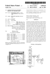
1
US006400462B1
(12)
(54)
United States Patent
(10) Patent N0.:
Hille
(45) Date of Patent:
US 6,400,462 B1
Jun. 4, 2002
SERVICE TOOL FOR SERVICING
6,009,284 A
* 12/1999 Weinberger et al. ......... .. 399/8
PRINTERS
6,061,603 A
*
(75) Inventor: David G. Hille, Roseville, CA (US)
5/2000 Papadopoulos et al. ..... .. 700/83
OTHER PUBLICATIONS
_
Lasertest NX60 Operators Manual, Nov. 18, 1996*
(73) Asslgnee? Hewlett'packard Company, P2110 A1t9>
CA (Us)
( * ) Notice:
Subject to any disclaimer, the term of this
Lasertest NX60 Operator’s Manual, available from Laser
Wizard, Valley Forge Business Center, 705 General Wash
in ton Avenue, Ste 202, NorthtoWn PA 19403—3683.,
1_g19_
pp
.
Patent 15 extended or adlusted under 35
Lasertest SX30 Operator’s Instruction Manual, available
U'S'C' 154(k)) by 0 days‘
from Laser Wizard, 705 General Washington Avenue, Ste
202, NorthtoWn PA 19403—3683., PP . 1—9, APP . B.
(21) APPl- N93 09/ 187,518
(
22
-
)
_
F1 d.
16
NOV
. 6
’
LBP—NX PCB Service Manual, available from Canon, Inc.,
30—2 Shimomaruko 3—chome ’ Ohta—l<u ’ Tokyo 146 ’ Japan ’
1998
1993, pp. 6—4 through 6—9.
(51)
Int. Cl.7 .............................................. .. G06F 13/00
* cited by examiner
(52)
US. Cl. ........................ .. 358/114; 358/468; 399/8;
Primary Exami”er—Mark Wallerson
399/9; 399/18; 399/81
(58)
(57)
ABSTRACT
Field of Search ....................... .. 358/11, 1.5, 1.12,
358/113, 1.14, 1.15, 1.16, 400, 401, 403,
Aprinter SerYiCe toolincludes a Controlpanelport Connector
for connect in g to th e con t ro 1 P ane 1 P ort o f a P rm ter, a
36 37 81 82
diagnostic port of the printer, and a display. The display
407, 468,. 399/8, 9, 10, 11, 13, 18, 19,
’
(56)
’
’
References Cited
controller dia nostic
g
P ort
connector for connectin
g
to a
displays a plurality of menus. A ?rst menu includes a
representation of buttons displayed on a control panel of the
printer. A second menu includes menu items Which provides
US. PATENT DOCUMENTS
9/1993
5,243,382 A
*
5,822,221 A
* 10/1998
ability to monitor printer functionality.
Takano et al. ............... .. 399/8
Groenteman .... ..
21 Claims, 16 Drawing Sheets
399/8
.0 4N ,9
g@D
11
7
v30
10
RESET I
FUSEFi
24621622623
,16
@25
U.S. Patent
Jun. 4, 2002
Sheet 1 0f 16
US 6,400,462 B1
oi
mm\Om b
K
FMEDG
Em a mw am I )
Z
3]
U.S. Patent
L
Jun. 4, 2002
Sheet 3 0f 16
US 6,400,462 B1
U.S. Patent
Jun. 4, 2002
Sheet 5 0f 16
US 6,400,462 B1
6A
wE?w
mmEDGE
U.S. Patent
Jun. 4, 2002
Sheet 8 0f 16
US 6,400,462 B1
No?
00?
_6.w5:m0n_
mZwO
EbQotBmEv
955E+_2_amE>o;: _H_D_:5E2w:E2n3;
wmEDGE
U.S. Patent
Jun. 4, 2002
Sheet 9 0f 16
US 6,400,462 B1
N:
I;
o:
_
“24cm
_:om.cwEno_O
E2 55
_22.2
wZwO
>Om
2E5rm64a5
95:0
Ell:
MmEDGE
U.S. Patent
Jun. 4, 2002
Sheet 11 0f 16
US 6,400,462 B1
mm?
PM;
om?
oca<>_m.Ia
EuA5><._inm:5
356:2m.g
__E|g|_
tc__>_.__Ea6wm._
M:.IDGE
U.S. Patent
Jun. 4, 2002
Sheet 12 0f 16
US 6,400,462 B1
mvw
:1.
03.
:91E552%
EmA1v>5<.2_En“.w5
|_z >_
Q6B.Sm5E.
wXzIwEoQ E6osamctE;
mNFEDGE
U.S. Patent
OnLine
Jun. 4, 2002
+
Sheet 13 0f 16
Form Feed
+
Enter
Power on Printer
US 6,400,462 B1
y?’
51
52
Form Feed
3/
Enter
}\1 54
153
TIME
Y\
150
FIGURE 13
U.S. Patent
OnLine
Jun. 4, 2002
+
Continue
Sheet 14 0f 16
+
Enter
Power on Printer
Continue
Enter
TIME
\
160
FIGURE 14
US 6,400,462 B1
‘:Y’Eb/"J
61
62
63
64
U.S. Patent
Jun. 4, 2002
FormFeed +
Item
Sheet 15 0f 16
+
US 6,400,462 B1
Menu
Power on Printer
Continue
Enter
Viv’
71
72
>173
}\174
TIME
h170
FIGURE 15
U.S. Patent
Jun. 4, 2002
FormFeed +
Sheet 16 0f 16
Print Fonts
+
Menu
Power on Printer
Continue
Enter
TIME
\
180
FIGURE 16
US 6,400,462 B1
yb/EY’
81
82
73
84
US 6,400,462 B1
1
2
SERVICE TOOL FOR SERVICING
PRINTERS
For example, the second menu includes menu items from
an engine test menu. Alternatively, the second menu
includes menu items Which alloW selection of a paper path
through the printer, or the second menu includes an indica
BACKGROUND
tion of the fuser temperature for the printer. In another the
The present invention concerns printers and pertains
menu can include a representation of buttons displayed on a
particularly to a service tool used to service printers.
While laser printers manufactured by HeWlett-Packard
Company have proved to be extremely reliable, there is the
occasional need for a printer to be serviced. When a printer
malfunctions, typically service personnel use a digital multi
10
meter and their past experience to determine the cause of the
device, through the port connector, service information
obtained from the printer.
problem. Diagnosing a problem often includes sWapping out
multiple parts in an effort to discover the source of the
problem. This type of service relies heavily on the skill of
the service personnel. The haphaZard nature of such diag
15
errors indicated by the current contents of the control panel
20
display. The detailed information includes, for example,
information about any failure in printer operation and
includes a suggested ?x. The softWare also can include a
nostic port on a DC controller Within printers. HoWever, the
service tool provides no testing of the printer formatter or
control panel of the printer. Further, the service tool Was
designed for Canon factory use, speci?cally for internal
manufacturing purposes. The service tool is expensive and
In one embodiment, softWare, running on the external
computing system, receives current contents of a control
panel display of the printer as part of the service information
and displays detailed information about any messages and
nosis can lead to increased material and labor costs due to
misdiagnosis of problems.
A Laser Driver Checker tool developed by Canon USA
Inc., having a business address of 2051 Mission College
Blvd., Santa Clara, Calif. 95054-1566, interfaces to a diag
control panel of a second type of printer.
In a preferred embodiment of the present invention, the
printer service tool includes a port connector for connecting
the printer service tool to an external computing device. The
printer service tool transfers to the external computing
Web broWser to be used for display the detailed information
as Well as updating the detailed information from a remote
Web site.
25
In the preferred embodiment, the printer service tool
implements macros selected by a user of the printer service
does not decode failure information automatically. The user
must interpret LED ?ashes to knoW What the printer engine
tool. For example, When the user selects a ?rst macro to be
failure is.
The Lasertest NX60 test tool, available from Laser
performed at start-up of the printer, the printer service tool,
upon detecting start-up of the printer, simulates button
30
WiZard, having a business address of Valley Forge Business
Center, 705 General Washington Avenue, Ste 202, North
presses on a control panel for the printer. This is done by the
printer service tool setting button values for the control
panel, and holding the button values for a predetermined
toWn Pa. 19403-3683, interfaces to the DC controller diag
nostic port and the control panel port of a printer. This ?rst
module is a test tool for a printer engine manufactured by
amount of time. For example, the ?rst macro places the
printer into a service mode or into an extended diagnostics
35
mode.
Canon, Inc. The Lasertest NX60 test tool is a second module
Which gives the ?rst module the capability to test the HP
LaserJet IIISI printer and the HP LaserJet 4Si printer avail
able from HeWlett-Packard Company, having a business
address of 3000 Hanover Street, Palo Alto, Calif. 94304.
The present invention provides an easy Way to diagnose
and troubleshoot printers. The printer service tool reduces
repair labor costs and material costs and alloWs service
Thus to interface to an HP LaserJet IIISI printer or an HP
personnel to accurately diagnose and identify the failing
?eld replaceable unit (FRU) Within the printer.
LaserJet 4Si printer, tWo separate modules are connected
together to create a single test tool. This combination is very
The printer service tool may be manufactured at a loW
cost and is easy to use, requiring little or no training to
confusing because the descriptions for the buttons on the
?rst module refer to a printer engine Which is different than
40
45
the printer engine utiliZed by the HP IIISI printer and the HP
LaserJet 4Si printer. The user must look at a draWing located
on the second module in order to interpret What the buttons
on the ?rst module do When testing a HP LaserJet IIISI or
a HP LaserJet 4Si printer. The test tool utiliZes a single 1><16
character display to shoW information. The result is that it is
confusing and hard to use Without training. The connector
for the diagnostic port on the DC Controller has all of its
electrical leads exposed, Which could cause additional harm
to the printer.
operate printer service tool. Simple menus are displayed on
a graphical display, Which also contribute to user friendli
ness. The macros alloW single button access into the printer
service mode or extended diagnostic mode. Errors captured
from the engine diagnostic port are automatically decoded,
displayed and described in text on the graphical display of
printer service tool, also contributing to the convenience of
the user.
The softWare interface is very useful because it automati
cally interprets numeric failure messages displayed by the
control panel and uses an integrated Web broWser to provide
55
a detailed description of the failure as Well as a suggested ?x.
Previously this information Was not decoded and the user
SUMMARY OF THE INVENTION
Would manually look the information up in a service manual.
In accordance With the preferred embodiment of the
present invention, a printer service tool is presented. The
printer service tool includes a control panel port connector
for connecting to the control panel port of a printer, a
controller diagnostic port connector for connecting to a
Also, in the preferred embodiment, the softWare is designed
in a modular fashion using HTML ?les so that ?x/failure
60
diagnostic port of the printer, and a display. The display
displays a plurality of menus. A ?rst menu includes a
representation of buttons displayed on a control panel of the
printer. A second menu includes menu items Which provides
ability to monitor printer functionality.
65
information can be updated over time by simply doWnload
ing the latest HTML ?les from a remote Web site. This
prevents the user from having to doWnload the entire pro
gram each time a ?le is updated. In addition to the features
mentioned above the softWare also has the same function
ality as the test tool menus. The printer service tool alloWs
the user to move betWeen test menus While displaying
DC-Controller failure messages, formatter error messages,
US 6,400,462 B1
3
4
high voltage drive signals, and the printer display all at the
user interface for printer service tool 10 is menu driven. A
128x64 piXel graphical display 20 is used to display infor
same time. This gives the user the advantage of seeing the
failure information While continuing to exercise the printer
in an attempt to determine the cause of the failure.
BRIEF DESCRIPTION OF THE DRAWINGS
FIG. 1 shoWs a printer service tool connected to a printer
in accordance With a preferred embodiment of the present
invention.
FIG. 2 shoWs a hardWare block diagram of the printer
service tool shoWn in FIG. 1 in accordance With a preferred
embodiment of the present invention.
FIG. 3 is a simpli?ed ?oWchart of ?rmWare eXecuted by
processor a processor Within the printer service tool shoWn
in FIG. 1 in accordance With a preferred embodiment of the
10
emitting diode (LED) 21 is lit When printer service tool 10
15
present invention.
FIG. 4 shoWs a block diagram of PC service tool softWare
Which Works With the printer service tool shoWn in FIG. 1
in accordance With a preferred embodiment of the present
invention.
FIG. 5 is a ?oWchart Which illustrates the How of the PC
service tool softWare in accordance With a preferred embodi
ment of the present invention.
FIG. 6 shoWs a simpli?ed eXample of a WindoW displayed
by the PC service tool softWare in accordance With a
20
FIG. 8 shoWs a printer control panel menu displayed by
the printer service tool shoWn in FIG. 1 in accordance With
a preferred embodiment of the present invention.
FIG. 9 shoWs another printer control panel menu dis
25
35
panel LCD data latch 37, a control panel LED buffer 38 and
a control panel sWitches latch 39. Test enable latch 42 and
engine status buffer 43 provide an interface to a DC con
troller diagnostic port connector 44. Control panel LCD data
latch 37, control panel LED buffer 38 and control panel
sWitches latch 39 provide an interface to control panel port
40
connector 40.
Control panel LCD data latch 37 and control panel
sWitches latch 39 capture control panel LCD Data and set
control panel sWitch values. This data comes from the
control panel port of printer 11. This alloWs printer service
45
tool 10 to emulate the control panels of printer 11 as Well as
read the contents of the printer display of printer 11. Control
panel LED buffer 38 puts on bus 45 the values of the LEDs
of printer 11 When a request comes from processor 34.
Test enable latch 42 enables different tests and settings in
the printer engine of printer 11. Engine status buffer 43 is
used to read error messages sent from the DC Controller of
printer 11. Engine status buffer 43 is also used to read
internal drive signals sent to the high voltage poWer supply
Within printer 11.
55
mode.
FIG. 16 shoWs the button sequence used to place a
Hewlett-Packard 3Si laser printer into eXtended diagnostics
60
DESCRIPTION OF THE PREFERRED
EMBODIMENT
Processor 34 acts as the bus arbitrator, controlling Which
device is on the bus and When. An overlay connector 31
provides an interface betWeen processor 34 and the sWitches
and LEDs shoWn in FIG. 1. An RS232 transceiver 35
converts +13V, —13V RS232 signals to TTL. Combined With
a UART Within processor 34, RS232 transceiver 35 and an
RS232 connector 36 alloW printer service tool 10 to com
municate With portable computer 12. Print voltages LEDs
include LEDs 21, 22 and 23, shoWn in FIG. 1. A crystal
(Xtal) 32 is a crystal oscillator Which provides a clock signal
FIG. 1 shoWs a printer service tool 10 connected to a
printer 11. Printer service tool 10 also can be connected,
through an RS232 compatible link 16, to a portable com
puter 12. Printer service tool 10 is a handheld test tool. The
having a business address of 2107 N 1st Street Number 590,
San Jose, Calif. 95131-2027. An 8-bit bus 45 alloWs pro
cessor 34 to communicate to a graphical LCD controller 41,
a test enable latch 42, an engine status buffer 43, a control
accordance With a preferred embodiment of the present
invention.
FIG. 13 shoWs the button sequence used to place a
Hewlett-Packard 4Si laser printer into service mode.
FIG. 14 shoWs the button sequence used to place a
Hewlett-Packard 3Si laser printer into service mode.
FIG. 15 shoWs the button sequence used to place a
mode.
button 26 is used to select the currently highlighted button
Within display 20.
microprocessor available from Microchip Technology Inc.,
30
played by the printer service tool shoWn in FIG. 1 in
Hewlett-Packard 4Si laser printer into eXtended diagnostics
A menu button 25 is used to select the menu that appears
on display 20. Adirectional arroW 27, a directional arroW 28,
FIG. 2 shoWs a hardWare block diagram of printer service
tool 10. A processor 34 is, for eXample, a PIC16C74A
preferred embodiment of the present invention.
FIG. 11 shoWs a laser test menu displayed by the printer
service tool shoWn in FIG. 1 in accordance With a preferred
embodiment of the present invention.
FIG. 12 shoWs a fuser temperature display menu dis
properly.
a directional arroW 29 and a directional arroW 30 are used to
played by the printer service tool shoWn in FIG. 1 in
accordance With a preferred embodiment of the present
invention.
FIG. 10 shoWs a paper path select menu displayed by the
printer service tool shoWn in FIG. 1 in accordance With a
detects the 5 volt poWer source of printer 11 is functioning
properly. An LED 22 is lit When printer service tool 10
detects the 12 volt poWer source of printer 11 is functioning
properly. An LED 23 is lit When printer service tool 10
detects the 24 volt poWer source of printer 11 is functioning
highlight buttons displayed Within display 20. A select
preferred embodiment of the present invention.
FIG. 7 shoWs an engine test menu displayed by the printer
service tool shoWn in FIG. 1 in accordance With a preferred
embodiment of the present invention.
mation.
Printer service tool 10 connects to the printer engine of
printer 11 via a cable 14 connected to the diagnostic port
found on the DC controller for printer 11. Printer service tool
10 also connects to the control panel port on the formatter of
printer 11 via a cable 15. This gives printer service tool 10
the ability to control and monitor the printer engine as Well
as test the formatter and control panel of printer 11.
Printer service tool 10 is housed in a 5.75“><0.81“><3.60“
plastic enclosure. A reset fuser button 24 is used to reset the
fuser in printer 11 after an error has occurred. A light
65
to processor 34.
Printer service tool 10 utiliZes a combination of a factory
diagnostic test port, located on the DC Controller of printer
US 6,400,462 B1
5
6
11, and the control panel port of printer 11, to gain low level
accessibility to the printer engine and formatter of printer 11.
All switches on the overlay of printer service tool 10 are
monitored and if any are pressed, execution of the ?rmware
breaks off into the necessary event handler. Speci?cally, in
a step 61, test port data and control panel data are retrieved.
This low level access allows printer 11 to be placed into
ready inhibit mode (a special mode used for troubleshooting
that allows printer 11 to operate in the presence of non-fatal
The appropriate values are then written to graphical display
20 of printer service tool 10. Additionally, tool switch data
errors) as well as to control of the different subassemblies
within printer 11. Printer service tool 10 also displays the
status of printer sensors, voltages, control signals, and
additional failure information presented by the DC Control
ler.
FIG. 3 is a simpli?ed ?owchart of ?rmware executed by
processor 34. The ?rmware resides in processor 34 and
are sampled (i.e., determine when a button on printer service
tool 10 has been pressed) and any required actions are taken.
10
cal display 20 of printer service tool 10 is blanked and the
serial port connected to the portable computer is monitored
provides all the logic and intelligence needed for printer
service tool 10 to operate properly.
During power on of processor 34, the ?rmware does all
necessary initialiZations of processor 34 and printer service
tool 10. As shown in FIG. 3, in a step 51, processor 34 is
initialiZed. In step 51, variable declarations are performed
and the functionality of processor 34 is set.
In a step 52, an interrupt handler is initialiZed to capture
instructions and data sent from the formatter of printer 11 to
for communication from the PC service tool software run
15
20
the control panel display of printer 11. The interrupt handler
is used to capture data and instructions that would normally
be sent to the control panel display of printer 11. This routine
allows the control panel display messages to be displayed on
graphical display 20 of printer service tool 10. If a portable
computer is attached to printer service tool 10, the PC
service tool software that resides on the portable computer
ning on portable computer 12. Printer service tool 10 has the
ability to communicate all information received from printer
11 to software residing on portable computer 12, through
serial link 16. This information includes the control panel
display contents obtained from printer 11. Using the control
panel display contents, the PC service tool software on
portable computer 12 decodes numeric failure messages and
provide detailed ?x/failure information. In a step 63, the
error status of the DC controller is decoded.
25
In a step 64, printer service tool 10 writes data to the
control panel of printer 11 and to the test port latches of
printer 11.
The PC service tool software located in portable computer
can also have access to the control panel display messages.
12 is an optional user interface. The PC service tool software
In a step 53 various con?guration activity is performed.
Variable values are set. Watch dog timer (WDT) is enabled.
In a step 62 a check is made to determine if a serial
connection has been established to a portable computer. If a
serial connection has been established, the menu on graphi
30
provides all the functionality of printer service tool 10 as
well as the ability to provide additional failure/?x informa
WDT resets processor 34 when processor 34 enters an
tion by giving further information regarding the numeric
unknown or looping state. The timer is powered up and
failure messages found on the display of the printer control
detection of brown out is initialized. Analog-to-digital (A/D)
conversion, timers and interrupts are con?gured. The input/
output (I/O) of processor 34 is also con?gured.
In a step 54, graphical display 20 is initialiZed.
panel. The PC service tool software is capable of displaying
35
PC service tool software requires that portable computer 12
In a step 55, a determination is made as to whether a
power-up feature has been enabled. The power up features
are events that must occur during power on of printer 11. For
example the service mode, extended diagnostic mode, and
40
ready inhibit are entered during power up of printer 11. If
processor 34 senses that one of these events are enabled it
immediately applies the proper signals to printer 11 as
printer 11 is powering up. This feature, implemented by
macros, is discussed in greater detail below.
In a step 56, all hardware latch values, all menu vectors
and all menu ?ag registers are initialiZed.
45
showing how printer service tool 10 operates.
The PC service tool software also integrates a web
browser, such as the Internet Explorer Web Browser avail
able from Microsoft Corporation, having a business address
at 16011 NE 36th Way, Redmond, Wash. 98073-9717. After
a connection between the PC service tool software and
sages. If a match is found, the PC service tool software
points the integrated web browser to the corresponding
HTML pages that describe the printer error as well as
provide ?x information. The HTML ?les are stored locally
on portable computer 11, but can be periodically updated
55
from information stored on the internet.
FIG. 4 shows a block diagram of the PC service tool
software on portable computer 12. The PC service tool
software includes a main form 70, a connection form 71, a
help form 72, HTML ?les 73, a main form module 74 and
an error in the printer engine. If so, the error value and a
written explanation of the error is written to graphical
is connected to printer service tool 10. Within the PC service
tool software is a search engine, which allows the user look
for display messages and errors. Also included is a manual
printer service tool 10, the PC service tool software reads the
control panel display of printer 11. The contents of the
display are compared with a list of possible display mes
After completion of step 56, processor 34 and printer
service tool 10 has been initialiZed. The ?rmware then enters
the main routine, beginning in a step 57. The main routine
is sequential and runs in a continuous loop. The ?rmware
controls what content is written to graphical display 20 and
de?nes how the menus will look and operate.
Printer errors are detected, decoded, and displayed.
Speci?cally, in step 57, overrun errors on the UART (within
processor 34) are checked. In a step 58, a check is made to
see if DC controller in printer 11 has indicated that there is
all the menus on printer service tool 10. Printer service tool
10 can operate as a standalone unit, while operation of the
60 a database 75.
display 20.
In a step 59, display data captured by interrupt handler
Main form 70 includes a web (HTML) browser, performs
monitoring and processes commands. Main form 70 also
code is written to graphical display 20 of printer service tool
includes a serial communication module. Connection form
10.
In a step 60, analog-to-digital (AID) conversion is per
formed on all analog signals. These include analog-to-digital
conversions of the fuser temperature and laser output power.
65
71 handles the connection to printer service tool 10. Con
nection form 71 includes a connection wiZard which helps
the user connect portable computer 12 to printer service tool
10 and establish communication between the PC service tool