1
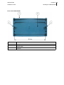
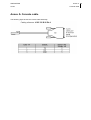
ONE20G/D/M
Installation Guide
Version: 1.0 - 500943
6 February 2008
ONE20G/D/M
Copyright, feedback 2
Installation Guide
Document properties
Subject
ONE20G/D/M
Manual type
Installation Guide
Version
1.0
Code
500943
Modification date
6 February 2008 ©OneAccess
Copyright notice
The law of 11 March 1957, paragraphs 2 and 3 of article 41, only authorizes, firstly, copies and reproductions strictly reserved for use by copyists and not for general use and, secondly, analyses and short
quotations for the purpose of example and illustration. Therefore, any representation or reproduction,
entire or partial, made without the consent of the author or his representatives is illegal’ (paragraph 1 of
article 40).
Any such representation or reproduction, made in any manner whatsoever, would therefore constitute
an infringement of the law as sanctioned by articles 425 and in accordance with the penal code.
Information contained in this document is subject to change without prior notice and does not constitute
any form of obligation on the part of OneAccess.
OneAccess and the distributors can in no case be held responsible for direct or indirect damage of any
kind incurred as a result of any error in the software or guide.
Every care has been taken to ensure the exactitude of information in this manual. If however you discover an error, please contact OneAccess After Sales Service division.
November 2005 Issue
1100 00 T 4023102 T 00 ind. A
OneOS operating system
The OneOS is a feature-rich operating system that guarantees a common feature set across the different
OneAccess product lines and a uniform support by maintenance and management tools.
The OneOS manual, which is a separate manual, describes the features of the latest version of the
OneOS operating system.
Your feedback
Your satisfaction about this purchase is an extremely important priority to all of us at OneAccess. Accordingly, all electronic, functional and cosmetic aspects of this new unit have been carefully and thoroughly
tested and inspected. If any fault is found with this unit or should you have any other quality-related comment concerning this delivery, please submit the Quality Comment Form on our web page at
www.oneaccess-net.com/telindus → Support.
3 ONE20G/D/M
Installation Guide
Table of contents
1
Safety instructions
1.1
1.2
1.3
1.4
1.5
2
Directives and standards
2.1
2.2
2.3
2.4
2.5
2.6
3
Power requirements
Dimensions
Environmental compliance
Installing the ONE20G/D/M
6.1
6.2
6.3
7
The different connectors on the back panel of the ONE20G/D/M
ISDN interface specifications
SHDSL line specifications
LAN interface specifications
WLAN interface specifications
4 port Ethernet switch specifications
Console port specifications
Technical characteristics
5.1
5.2
5.3
6
What is the ONE20G/D/M?
ONE20G/D/M Router family overview
Hardware description
The front panel LED indicators
Rear view of the ONE20G/D/M
The ONE20G/D/M motherboard
Interface description
4.1
4.2
4.3
4.4
4.5
4.6
4.7
5
Statements
Environmental information
Safety compliance
Over-voltage and over-current protection compliance
EMC compliance
Environmental compliance
Router description
3.1
3.2
3.3
3.4
3.5
3.6
4
Safety information
Unpacking
Selecting a site
Connection precautions
Back panel earth connection
Opening and closing the housing
Installing the WLAN antenna
Mounting the ONE20G/D/M on a wall
Powering up the ONE20G/D/M
Annex
Annex A:Console cable
Table of contents
ONE20G/D/M
Installation Guide
Index
Table of contents 4
5 ONE20G/D/M
Installation Guide
Table of contents
ONE20G/D/M
Installation Guide
1
Chapter 1 6
Safety instructions
Safety instructions
This chapter gives some important safety instructions to take into account when using and installing the
ONE20G/D/M. The following gives an overview of this chapter:
•
1.1 - Safety information
•
1.2 - Unpacking
•
1.3 - Selecting a site
•
1.4 - Connection precautions
•
1.5 - Back panel earth connection
7 ONE20G/D/M
Installation Guide
1.1
Chapter 1
Safety instructions
Safety information
IMPORTANT SAFETY INSTRUCTIONS
•
Disconnect the power supply before installing, adjusting or servicing the unit. Always disconnect the
AC input first.
•
The external power supply is connected on the rear panel of the device, and is delivered together with
the ONE20G/D/M.
•
To connect the power supply, proceed as follows:
-
Connect the DC input jack from the power supply to the DC 12V power input on the rear panel of
the device.
-
Secure the power supply connection by installing the DC power supply cord into the foreseen clip.
-
Connect the power supply to an AC electrical outlet (100-240 VAC). Plugging in the power supply
turns the router on.
•
Do not use another type of power supply then the one prescribed by OneAccess.
•
Over current Protection: This device requires that the building’s electrical installation is designed for
protection against short-circuit (over-current) protection. A fuse or circuit breaker no larger than 240
VAC, 10A must be used on the phase conductors.
SAFETY WARNING
•
To avoid damage to the unit, please observe all procedures described in this chapter.
•
It is essential that, if a device has got an earth stud on the back panel, that this is effectively connected
to earth. Otherwise, in case of electrical problems, other devices connected to the ONE20G/D/M
could be damaged. Also refer to 1.5 - Back panel earth connection.
Ensure that the unit and its connected equipment all use the same power and ground, to reduce noise
interference and possible safety hazards caused by differences in ground or earth potentials.
ONE20G/D/M
Installation Guide
1.2
Chapter 1 8
Safety instructions
Unpacking
Checking the shipping carton
Rough handling during shipping causes most early failures. Before installation, check the shipping carton for signs of damage:
•
If the shipping carton is damaged, please place a claim with the carrier company immediately.
•
If the shipping carton is undamaged, do not dispose of it in case you need to store the unit or ship it
in the future.
1.3
Selecting a site
WARNING
Always place the unit on its feet without blocking the air vents.
Install the unit in an area free of extreme temperatures, humidity, shock and vibration. Position it so that
you can easily see and access the front panel and its control indicators. Leave enough clearance at the
back for cables and wires. Position the unit within the correct distances for the different accesses and
within 2m of a power outlet.
9 ONE20G/D/M
Chapter 1
Installation Guide
1.4
Safety instructions
Connection precautions
ESD WARNING
The circuit boards are sensitive to electrostatic discharges (ESD) and should be handled with care. It is
advisable to ensure an optimal electrical contact between yourself, the working area and a safety ground
before touching any circuit board. Take special care not to touch any component or connector on the
circuit board.
EMC WARNING
The OneAccess access products are fully EMC compliant. To ensure compliance with EMC directive 89/
336/EEC, shielded cables or ferrite beads have to be used.
NOTE
This unit may be powered by an IT power system.
The connectors of the ONE20G/D/M should only be connected to the following circuit types:
Connector
Connector label
Connector type
Circuit type
SHDSL
SHDSL
RJ45
TNV-1
LAN interface1
ETHERNET/SWITCH
RJ45
SELV
PSTN interface2
PSTN
RJ45
TNV-1
RS232 Interface3
Console
RJ45
SELV
FXS Interface
FXS
RJ45
TNV-2
FXO Interface
FXO
RJ45
TNV-3
T0/S0 interface
ISDN BRI
RJ45
TNV-3
Clinching stud
Earth
Earth stud
1. 10/100 Mbps interface
2. V.32(bis)/V.34/V.90/V.92
3. V.24
•
SELV (Safety Extra Low Voltage): local connection (e.g. PC to ONE20G/D/M) or leased line inside
the building.
•
TNV-1 (Telecom Network Voltage): telephone line, leased line outside the building.
•
TNV-2: PSTN from PABX inside the building; Telecommunications Network Voltage.
•
TNV-3: PSTN from operator PABX outside the building.
ONE20G/D/M
Chapter 1 10
Installation Guide
1.5
Safety instructions
Back panel earth connection
Safety
Some versions of the ONE20G/D/M might be equipped with enhanced protection components, and have
an earth stud on the back panel.
It is essential that, if a device has got an earth stud on the back panel, that this is effectively connected
to earth. Otherwise, in case of electrical problems, other devices connected to the ONE20G/D/M could
be damaged.
Earth Connection
To connect an earth wire to the clinching stud on the back panel, use:
•
2 round M3 washers; these are delivered with the ONE20G/D/M.
•
1 M3 nut; this is also delivered with the ONE20G/D/M.
•
1 M3 ring tongue; this is not delivered with the ONE20G/D/M.
Proceed as follows:
Step
Action
1
Slide one of the round M3 washers over the clinching stud.
2
If not already done so, the earth cable that will be connected to the clinching stud, must
be equipped with an M3 ring tongue.
3
Slide the M3 ring tongue of the earth cable over the clinching stud.
4
Slide the second M3 round washer over the clinching stud.
5
Use the M3 nut to fix everything; make sure it is firmly fixed.
11 ONE20G/D/M
Installation Guide
Chapter 1
Safety instructions
ONE20G/D/M
Installation Guide
2
Chapter 2 12
Directives and standards
Directives and standards
This chapter details the list of standards, which the ONE20G/D/M complies with. The following gives an
overview of this chapter:
•
2.1 - Statements
•
2.2 - Environmental information
•
2.3 - Safety compliance
•
2.4 - Over-voltage and over-current protection compliance
•
2.5 - EMC compliance
•
2.6 - Environmental compliance
13 ONE20G/D/M
Installation Guide
2.1
Chapter 2
Directives and standards
Statements
www.oneaccess-net.com/telindus → Products → choose a product → Downloads → Certificates
Hereby, OneAccess declares that this ONE20G/D/M complies with the essential requirements and other
relevant provisions of Directive 1999/5/EC.
Hierbij verklaart OneAccess dat deze ONE20G/D/M overeenstemt met de essentiële vereisten en
andere relevante bepalingen van Richtlijn 1999/5/EC.
Par la présente, OneAccess déclare que ce ONE20G/D/M est en conformité avec les exigences essentielles et autres articles applicables de la Directive 1999/5/EC.
Hiermit, OneAccess erklärt daß dieser ONE20G/D/M in Fügsamkeit ist mit den wesentlichen
Anforderungen und anderen relevanten Bereitstellungen von Direktive 1999/5/EC.
Mediante la presente, OneAccess declara que el ONE20G/D/M cumple con los requisitos esenciales y
las demás prescripciones relevantes de la Directiva 1999/5/CE.
A OneAccess declara que o ONE20G/D/M cumpre os principais requisitos e outras disposições da
Directiva 1999/5/EC.
Col presente, OneAccess dichiara che questo ONE20G/D/M è in acquiescenza coi requisiti essenziali e
stipulazioni attinenti ed altre di Direttivo 1999/5/EC.
Με το παρόν η OneAccess δηλώνει ότι το ONE20G/D/M είναι συµµορφούµενο µε τις βασικές απαιτήσεις
και µε τις υπόλοιπες σχετικές διατάξες της οδηγίας 1999/5/EC.
ONE20G/D/M
Installation Guide
2.2
Chapter 2 14
Directives and standards
Environmental information
The crossed-out wheeled bin means that within the European Union the product must be taken to separate
collection at the product end of life. This applies to the device but also to any accessories marked with this symbol.
Do not dispose of these products as unsorted municipal waste.
If you need more information on the collection, reuse and recycling systems, please contact your local waste
administration. You can also contact us for more information on the environmental specifications of our products.
De doorgestreepte container wil zeggen dat binnen de Europese gemeenschap het product voor gescheiden afvalverzameling
moet worden aangeboden aan het einde van de levensduur van het product. Dit geldt voor het toestel, maar ook voor alle
toebehoren die van dit symbool voorzien zijn. Bied deze producten niet aan bij het gewone huisvuil.
Indien u meer informatie wenst over de systemen voor inzameling, hergebruik en recyclage, gelieve dan uw lokale afvaldiensten
te contacteren. U kan ook ons contacteren wanneer u informatie wenst over de milieu aspecten van onze producten.
Le symbole de la poubelle sur roues barrée d’une croix signifie que ce produit doit faire l’objet d’une collecte sélective en fin de
vie au sein de l’Union Européenne. Cette mesure s’applique non seulement à vorte appareil mais également à tout autre
accessoire marqué de ce symbole. Ne jetez pas ces produits dans les ordures ménagères non sujettes au tri sélectif.
Si vous souhaitez plus d'information concernant les systèmes de collecte, de réutilisation et de recyclage, veuillez contactez votre
service de gestion de déchets local. Vous pouvez également nous contacter pour obtenir plus d’information au sujet des
spécifications environnementales de nos produits.
Das Symbol der durchgestrichenen Abfalltonne auf Rädern bedeutet dass das Produkt in der Europäischen Union einer
getrennten Mülsammlung zugeführt werden muss. Dies gilt sowohl für das Produkt selbst, als auch für alle mit diesem Symbol
gekennzeichneten Zubehörteile. Diese Produkte dürfen nicht über den unsortierten Hausmüll entsorgt werden.
Wenn Sie mehr Informationen brauchen über die Sammlung und Recycling Systemen, bitte konsultieren Sie Ihre örtliche Abfälle
Verwaltung. Für mehr Informationen über die Umweltaspekten unserer Produkte, wenden Sie sich an unserer Kundendienst.
15 ONE20G/D/M
Installation Guide
2.3
Chapter 2
Directives and standards
Safety compliance
•
EN60950-1 - 1st edition: Safety of information technology equipment, including electrical business
equipment.
•
Class 1 equipment for Table Tops with 115/230 Vac internal power supply.
•
Class 3 equipment for …
-
Table Tops with 115/230 Vac external power supply adapter
-
Table Tops with -48 Vdc internal power supply
-
Card Versions.
2.4
Over-voltage and over-current protection compliance
The over-voltage and over-current protection complies with ITU-T K.44 and ETSI ETS 300 386-2 recommendations.
2.5
EMC compliance
•
EN55022 B Emissions
•
EN55024 Immunity
•
EN61000-3-2 Harmonics
•
EN61000-3-3 Voltage fluctuations and flicker
•
EN61000-4-2 ESD
•
EN61000-4-3 Radiated immunity
•
EN61000-4-4 EFT/burst
•
EN61000-4-5 Surge
•
EN61000-4-6 Conducted immunity
•
EN61000-4-8 Power magnetic field immunity
•
EN61000-4-11 Voltage dips & drops
•
ENV50204 Radiated immunity against digital radio telephone
•
EN300386 V.1.3.3 Ems Requirements
2.6
Environmental compliance
•
Storage conditions: ETSI ETS 300 019-1-1 Class 1.1. In addition, the storage temperature has to be
between -25 to +70°C
•
Transport conditions: ETSI ETS 300 019-1-2 Class 2.3
•
Stationary use conditions: ETSI ETS 300 019-1-3 Class 3.2. In addition, a relative humidity between
0 to 95% non-condensing and an ambient operational temperature between -10 to 50°C is supported.
•
Maximum altitude: 3000m
•
International protection (IP) class of protection against solid and liquids: IP40
•
In use: Temperature Controlled.
-
Test specification (Part1 Classification of environmental conditions):
›
Class T3.1 (normal)
›
Class T3.1 (exceptional)
ONE20G/D/M
Installation Guide
3
Chapter 3 16
Router description
Router description
This chapter describes the ONE20G/D/M front and rear panels, and the associated technical characteristics. The following gives an overview of this chapter:
•
3.1 - What is the ONE20G/D/M?
•
3.2 - ONE20G/D/M Router family overview
•
3.3 - Hardware description
•
3.4 - The front panel LED indicators
•
3.5 - Rear view of the ONE20G/D/M
•
3.6 - The ONE20G/D/M motherboard
17 ONE20G/D/M
Installation Guide
3.1
Chapter 3
Router description
What is the ONE20G/D/M?
The ONE20G/D/M is a secure SHDSL router. The SHDSL multi-pair interface offers a bandwidth up to
22Mbps over up to 4 copper pairs. The router relies on the robust OneOS software, the OneAccess IP
software designed for the delivery of enterprise grade services such as Quality of Service, IP VPN and
Wireless LAN.
High Speed DSL Access
The ONE20G/D/M includes a SHDSLbis interface up to 4 copper pairs. This provides line rates up to
22Mbps on short distances and up to 10Mbps on operator standard loop lengths. The various pair bonding techniques make it suitable for any type of DSL infrastructure. The symmetrical line rates of SHDSL
perfectly match the traffic profiles of business users.
HIGH NETWORK AVAILABILITY
A dedicated Ethernet interface is available as a backup when the DSL network is not available. Traffic
is automatically routed to the available network. Alternatively this interface can be used for a DMZ zone
(De-Militarised Zone). With a routing performance of over 20Mbps bidirectionally the ONE20G/D/M can
also be used as a full service CPE with Ethernet uplink behind a simple NTU. Optionally ISDN S0 interfaces are also available as a backup, providing continuous access to the Internet. It can also be used as
an access point for telecommuters or remote equipment configuration.
FULL SERVICE ROUTER
As communication over the Internet is cheaper than other alternatives, companies use or want to use it
not only for browsing and e-mail, but also for many other services like business processes between
offices and with home workers, web hosting. On their local network they need wired and wireless access.
The ONE20G/D/M provides secured Internet access through a stateful inspection firewall. Employees
working at home and personnel on the road can use the business applications based on central databases through IP VPNs.
The ONE20G/D/M also supports network based VPNs based on MPLS / IP and on VPLS / VLAN technology. It provides best-in-class IP Quality of Service features including real-time processing of high priority, delay sensitive applications and guaranteed bandwidth for selected flows. Each of the 4 LAN ports
can be reserved for a server. Specific policies can be applied per port. The optional wireless LAN gives
access to different types of users. Several user authentication schemes and policy based routing can be
applied so that a public hotspot service can be offered while securing the company’s LAN from intrusions.
Accelerated Deployment And Service Provision
As all ONE products, the ONE20G/D/M uses the Industry standard Command Line Interface (CLI). This
facilitates the configuration management for the service provider’s technicians and integrates rapidly
with automated tools. Several auto discovery and update features make the network roll-out straightforward.
Technicians or the customer install the units with a standard configuration. Once connected to the network the ONE20 automatically retrieves all customer specific information from the service provider’s
databases and thus becomes ready for the service. A set of embedded tools and service level indicators
enable responsive customer support. On the other hand a web based user interface provides the customer with all the service information that relevant to him.
ONE20G/D/M
Chapter 3 18
Installation Guide
3.2
Router description
ONE20G/D/M Router family overview
Different versions exist of the OneAccess. The name of each version indicates the hardware characteristics according to the following table:
Characters
Description
G
1 pair SHDSL
D
2 pair SHDSL
M
4 pair SHDSL
W
WIFI option (b/g)
S
Encryption (incl. hardware accelerator); otherwise only DES software encryption
5E
A 4 port Ethernet switch and an extra Ethernet interface.
-2B
2 BRI
Example
ONE20-2B-SM5E
This is a One20, with:
•
2 BRI interfaces
•
a hardware accelerator for encryption
•
4 SHDSL line pairs
•
a 4 port Ethernet switch and 1 ethernet interface
19 ONE20G/D/M
Installation Guide
3.3
Chapter 3
Router description
Hardware description
The ONE20G/D/M motherboard is equipped with the following interfaces:
•
SHDSL line connector
•
Console port
•
Managed switch with 4 ports
•
Additional Ethernet port
•
WLAN 802.11b/g
For more information, refer to 4.1 - The different connectors on the back panel of the ONE20G/D/M.
Optional extra connectors are:
•
ISDN BRI connectors.
ONE20G/D/M
Installation Guide
3.4
Chapter 3 20
Router description
The front panel LED indicators
This section gives an overview of the front panel LEDs and what they indicate. The following gives an
overview of this section:
•
3.4.1 - Introducing the front panel LEDs
•
3.4.2 - LED states
21 ONE20G/D/M
Chapter 3
Installation Guide
3.4.1
Router description
Introducing the front panel LEDs
When all the connections are made and the ONE20G/D/M is powered, the LEDs on the front panel
reflect the actual status of the device.
The following figure shows the front panel LED indicators of the ONE20G/D/M:
LED states
One front panel LED can reflect different status modes by the way it lights up. The front panel LEDs can
light up as follows:
LED state
LED duty cycle
Description
OFF
0%
The LED never lights up.
ON
100 %
The LED lights up continuously.
blinking
50 %
The LED is as much lit as it is out.
flashing
75 %
The LED lights up during 75% of the time, i.e. 1,5 seconds ON
and 0,5 seconds OFF.
ONE20G/D/M
Chapter 3 22
Installation Guide
3.4.2
Router description
LED states
The state of the LEDs indicates the following:
LED name
Colour
Description
Status
Bicolour
•
OFF: No input power.
•
ON - green: Switched on and operational.
•
ON - red: Switched on and not operational.
•
Blinking green: (Re)boot in progress.
•
OFF: None of the uplink interfaces (SHDSL, mobile, ISDN data
backup) is configured.
•
ON - green: The SHDSL uplink is synchronised.
•
ON - red: None of the uplinks is synchronised (although at least
one configured).
•
Blinking green: None of the uplinks is synchronised but at least
one uplink synchronisation is in progress.
•
Flashing green: The SHDSL uplink is not synchronised, but a
backup interface (ISDN or Mobile) is up.
•
OFF: No IP routing has been configured.
•
ON - green: All IP interfaces on the SHDSL link are up
•
ON - red: All IP interfaces are down
•
Blinking green: At least one IP interface is up and at least one is
not up on the active uplink.
•
Flashing green: All IP interfaces on the backup link (ISDN or
Mobile) are up.
•
OFF: Not in use.
•
ON - green: The WLAN interface is up.
•
Blinking green: Traffic in progress.
•
OFF: Not configured for voice service.
•
ON - green: Configured and operational voice service.
•
ON - red: Malfunction in the voice service.
•
Blinking green: Voice service is configured, verification of voice
function in progress.
•
OFF: There is no voice communication on any of the voice ports.
•
ON - green: There is voice communication on one of the voice
ports.
Uplink
IP
WLAN
Aux
Com
Bicolour
Bicolour
Green
Bicolour
Green
23 ONE20G/D/M
Installation Guide
3.5
Chapter 3
Router description
Rear view of the ONE20G/D/M
This section describes the various types of ONE20G/D/M rear panels, so that the user can identify the
interface type and port numbering.
The following gives an overview of the different models of the ONE20G/D/M:
•
One20G/D/M-W on page 24
•
One20G/D/M-2B-W on page 25
For a description of the meaning of the different model names, refer to 3.2 - ONE20G/D/M Router family
overview, and the following figures.
Note that in this chapter, the connectors that are present on the ONE20G/D/M by default, are not mentioned in the name of the device, only the optional extra connectors are mentioned in the name.
For a detailed description of the function of the different connectors, refer to 4.1 - The different connectors on the back panel of the ONE20G/D/M.
ONE20G/D/M
Chapter 3 24
Installation Guide
Router description
One20G/D/M-W
The following figure shows the back panel of the basic ONE20G/D/M:
Following connectors are present:
Connector(s)
Label
Type
Function
SHDSL
SHDSL
RJ45
SHDSL line connector
Console
CONSOLE
RJ45
V.24 DTE interface
Ethernet
ETHERNET
RJ45
Ethernet LAN connector
4 port Ethernet
switch
SWITCH – E0-0/0 - E3-0/3
RJ45
Ethernet LAN connectors
WLAN
-
SMA
Wireless LAN connectors
Power
12V-2A
DC input
jack
Power input
25 ONE20G/D/M
Chapter 3
Installation Guide
Router description
One20G/D/M-2B-W
The following figure shows the back panel of a ONE20G/D/M with 2 BRI connectors:
Following connectors are present:
Connector(s)
Label
Type
Function
SHDSL
SHDSL
RJ45
SHDSL line connector
Console
CONSOLE
RJ45
V.24 DTE interface
Ethernet
ETHERNET
RJ45
Ethernet LAN connector
4 port Ethernet
switch
SWITCH – E0-0/0 - E3-0/3
RJ45
Ethernet LAN connectors
ISDN
ISDN BRI – L0-5/0 - L1-5/1
RJ45
ISDN connection, NT mode
WLAN
-
SMA
Wireless LAN connectors
Power
12V-2A
DC input
jack
Power input
ONE20G/D/M
Installation Guide
3.6
Chapter 3 26
Router description
The ONE20G/D/M motherboard
The figure below shows the motherboard, and the position of the straps on the ONE20G/D/M motherboard:
27 ONE20G/D/M
Installation Guide
Chapter 3
Router description
ONE20G/D/M
Installation Guide
4
Chapter 4 28
Interface description
Interface description
This chapter gives an overview of the different connectors on the back of the ONE20G/D/M. The following gives an overview of this chapter:
•
4.1 - The different connectors on the back panel of the ONE20G/D/M
•
4.2 - ISDN interface specifications
•
4.3 - SHDSL line specifications
•
4.4 - LAN interface specifications
•
4.5 - WLAN interface specifications
•
4.6 - 4 port Ethernet switch specifications
•
4.7 - Console port specifications
29 ONE20G/D/M
Chapter 4
Installation Guide
4.1
Interface description
The different connectors on the back panel of the ONE20G/D/M
Depending on the version of the ONE20G/D/M, some of these connectors may or may not be present.
Refer to 3.5 - Rear view of the ONE20G/D/M for an overview of the different versions that exist.
The following table gives an overview of the possible connectors located at the back of the ONE20G/D/
M and explains their function:
Label
Function
SHDSL
This RJ45 connector is the SHDSL line connector.
Connect one side of an SHDSL line cable (not included) to the LINE connector of
the ONE20G/D/M and the other side to an SHDSL outlet.
For optimum performance, the used line pairs have to be properly twisted
pairs.
Refer to 4.3 - SHDSL line specifications for the pin lay-out of this connector.
CONSOLE
This RJ45 connector is a V.24 DTE interface. This enables you to manage the
ONE20G/D/M locally. For more information, refer to 4.7 - Console port specifications.
ETHERNET
These RJ45 connectors are the Ethernet LAN connectors. There are 1+4 Ethernet
LAN connectors on the ONE20G/D/M.
SWITCH, E0-0/0
... E3-0/3
The separate Ethernet interface can be used as main WAN link or as a back-up
WAN link interface. The Ethernet switch is VLAN manageable.
Connect one side of an Ethernet LAN cable (not included) to the LAN connector of
the ONE20G/D/M and the other side to an Ethernet network outlet. Each LAN
interface supports 10/100 Mbps auto-sense and auto cross-over.
Refer to 4.4 - LAN interface specifications for the pin lay-out of this connector.
ISDN-BRI
L0-5/0 ... L7-5/7
These RJ45 connectors are the ISDN connectors. The number of ISDN connectors will vary depending on the model of the ONE20G/D/M.
Connect one side of an ISDN cable (not included) to the ISDN BRI connector(s) of
the ONE20G/D/M and the other side to an ISDN outlet.
Refer to 4.2 - ISDN interface specifications for the ISDN specifications of this connector.
12VDC-2A
This is the power input. Insert the plug of the external power supply in this socket.
Secure the power supply connection by installing the DC power supply cord into
the plastic ring provided on the back panel.
Refer to 5.1 - Power requirements for the power specifications of the ONE20G/D/
M.
This is the earth stud. Connect the earth wire to this stud. Refer to 1.5 - Back panel
earth connection for more information.
Contact the appropriate electrical inspection authority or an electrician if you are
uncertain that suitable grounding is available.
ONE20G/D/M
Chapter 4 30
Installation Guide
4.2
Interface description
ISDN interface specifications
Specifications
•
The ONE20G/D/M motherboard supports up to 4 ISDN interfaces. The interfaces.are of type NT. For
use as TE a crossed cable must be used.
•
compliant with ITU-T I.430 section 10
•
Connector: RJ45 connector, 1 connector per interface
•
Cable to be used: shielded cable
•
The factory configuration of these interfaces is T0 mode. Do not connect the interfaces with a public
ISDN access without ensuring that the strap positions are correct. The product can be irreversibly
damaged otherwise.
•
You can connect/disconnect the power supply of all ISDN ports by using the command CLI(voiceport)# [no] power-source-one without changing the default factory strap settings.
•
Cables connected to the T0/S0 (ISDN/BRI) interfaces must always be shielded, in order to respect
the environmental norm.
Mother board connectors
The following table shows the connector layout of the RJ45 ISDN connector:
Pin
NT function
Figure
1
not connected
-
2
not connected
-
3
Receive A (+)
input
4
Transmit A (+)
output
5
Transmit B (-)
output
6
Receive B (-)
input
7
not connected
-
8
not connected
-
31 ONE20G/D/M
Installation Guide
Chapter 4
Interface description
Straps
Every ISDN interface has a strap (ST13, ST14) making it possible to configure a 100 Ohms impedance
adaptation.
Refer to 3.6 - The ONE20G/D/M motherboard for the position of these straps.
Description
The straps allow to connect a 100 Ohms impedance adaptation or not; the straps can be used in sending, in receiving or in both sending and receiving direction.
The following figure illustrates the functions of the straps:
ONE20G/D/M
Chapter 4 32
Installation Guide
Interface description
Examples of configurations
•
Configuration 1:
Strap settings
Description
•
100 Ω impedance adaptation disconnected.
•
•
Configuration 2:
Strap settings
Description
•
•
100 Ω impedance adaptation connected, for both
transmission and reception.
33 ONE20G/D/M
Chapter 4
Installation Guide
4.3
Interface description
SHDSL line specifications
•
Single pair, dual pair, 4 pair line access
•
Connector: RJ45
•
Impedance: 135 Ω
•
Cable to be used: 2*2*CAT5E twisted pair
•
Coding: TCPAM, compliant to ITU-T G.991.2; G.SHDSL, and G.SHDSL.bis via TCPAM-16 and
TCPAM-32
•
Line speeds:
-
Single pair: 192 … 5696 in steps of 64kbps
-
Two pair: 384 … 11392 in steps of 128kbps
-
Four pair: 768 … 22784 in steps of 256kbps
•
Handshaking: compliant G.994.1 (automatic speed negotiation) or fixed speed
•
Performance monitoring: compliant G.826 (errored seconds, severely errored seconds, unavailability
seconds)
The line connector lay-out
The following table shows the connector layout of the RJ45 line connector:
Pin
Signal
1
line 2
2
line 2
3
line 3 (only on the 4P versions)
4
line 1
5
line 1
6
line 3 (only on the 4P versions)
7
line 4 (only on the 4P versions)
8
line 4 (only on the 4P versions)
Figure
ONE20G/D/M
Chapter 4 34
Installation Guide
4.4
Interface description
LAN interface specifications
•
Connector: RJ45 (EIA/TIA 568B)
•
Cable to be used: standard Ethernet cable (shielded UTP Cat. 5)
•
Applicable standards: IEEE 802.3 (10Mbps Ethernet), IEEE 802.3u (100Mbps Ethernet)
•
Speed: 10/100 Mbps auto-sense
•
DTE/DCE auto cross-over
•
VLAN support (up to 12 VLANs)
•
The following LEDs are available built-in on each Ethernet interface connector:
Colour
Description
Green
•
OFF: link inactive.
•
ON: link active.
•
OFF: no traffic in progress.
•
ON: traffic in progress.
Yellow
The following table shows the connector layout of the RJ45 Ethernet LAN interface connector:
Pin
Signal
DTE
DCE
1
transmit (+)
Out
In
2
transmit (-)
Out
In
3
receive (+)
In
4
not used
-
5
not used
-
6
receive (-)
In
7
not used
-
8
not used
-
Out
Figure
35 ONE20G/D/M
Installation Guide
4.5
WLAN interface specifications
•
WIFI version: 802.11b/g
•
Compliant with the IEEE 802.11-2005 recommendation
•
maximum data rate: 54 Mbits/second
•
Operational frequency: 2,4GHz
•
Default radio channel: 11
•
WEP and WPA encryption
Chapter 4
Interface description
ONE20G/D/M
Installation Guide
4.6
Chapter 4 36
Interface description
4 port Ethernet switch specifications
•
Number of ports: 4
•
Connectors: RJ45 (EIA/TIA 568B)
•
Applicable standards: IEEE 802.3 (10Mbps Ethernet), IEEE 802.3u (100Mbps Ethernet)
•
Characteristics:
•
-
10 / 100 Mbps auto-sense
-
Half or full duplex
-
Auto-negotiation
-
Auto detection of crossover/straight cable (auto MDI/MDIX detection)
Meaning of LED colours:
-
Lit green LED: link active
-
Blinking yellow LED: traffic in progress
•
The layout of the connectors is identical to the LAN interface, refer to 4.4 - LAN interface specifications: transmission pairs 1-2, receive pairs 3-6
•
Cable to be used: shielded crossover/straight cables with 4 twisted pairs
37 ONE20G/D/M
Chapter 4
Installation Guide
4.7
Interface description
Console port specifications
•
Connector: RJ45 (EIA/TIA 568B)
•
Data:
-
RS232
-
9600 bps
-
8 data bits
-
no parity
-
1 stop bit
The following table shows the connector layout of the RJ45 Console connector:
Pin
Abbreviation
Signal
DCE
1
RD
Received data
Out
2
TD
Transmitted data
In
3
GND
Ground
-
4
NC
Not connected
-
5
NC
Not connected
-
6
Cable type
7
RTS
Request To Send
In
8
CTS
Clear To Send
Out
Figure
-
•
A console cable for router configuration and maintenance only requires TX, RX and GND to be connected; refer to Annex A: - Console cable for more information about the cable.
•
If pin 6 is connected to ground (pin 3), the cable is then identified as a cable connected to an asynchronous terminal. In that case, CTS and RTS can be used.
ONE20G/D/M
Installation Guide
5
Chapter 5 38
Technical characteristics
Technical characteristics
This chapter describes technical characteristics of the ONE20G/D/M. The following gives an overview
of this chapter:
•
5.1 - Power requirements
•
5.2 - Dimensions
•
5.3 - Environmental compliance
39 ONE20G/D/M
Installation Guide
5.1
Chapter 5
Technical characteristics
Power requirements
Power adapter to be used: Switched Power Module 100-240 VAC, 20W, Vout=12 Vdc, Iout=2 A (all versions).
Do not use another type of power supply than the one recommended by OneAccess.
5.2
Dimensions
•
Height: 68 mm
•
Width: 275 mm
•
Depth: 152 mm
•
Weight: 1 kg
ONE20G/D/M
Chapter 5 40
Installation Guide
5.3
Technical characteristics
Environmental compliance
Storage conditions:
The following conditions apply:
Storage conditions
Values
Temperature
- 25 °C <= T <= 55 °C
Relative humidity (HR)
5% <= HR <= 80%
Absolute humidity
<= 24g / m³
Altitude
<= 2500m
Operating conditions:
The following conditions apply:
Operating conditions
Values
Temperature
0 °C <= T <= 45 °C
Relative humidity
5% <= HR <= 80%
Absolute humidity
<= 24g / m³
Altitude
<= 2500m
41 ONE20G/D/M
Installation Guide
Chapter 5
Technical characteristics
ONE20G/D/M
Installation Guide
6
Chapter 6 42
Installing the ONE20G/D/M
Installing the ONE20G/D/M
This chapter explains how to install the ONE20G/D/M. The following gives an overview of this chapter:
•
6.1 - Opening and closing the housing
•
6.2 - Installing the WLAN antenna
•
6.3 - Mounting the ONE20G/D/M on a wall
43 ONE20G/D/M
Chapter 6
Installation Guide
6.1
Installing the ONE20G/D/M
Opening and closing the housing
When you want to change the DIP switch settings, you have to open and close the housing. This section
explains how to do so.
Opening the housing
To open the housing of the ONE20G/D/M, proceed as follows:
Step
Action
1
Disconnect the external power supply.
2
Unfasten both rear panel screws and remove them.
3
Unclip the lower part of the front panel.
4
Remove the cover.
Closing the housing
To close the housing of the ONE20G/D/M, proceed as follows:
Step
Action
1
Replace the cover.
2
Fix the lower part of the front panel.
3
Fasten both rear panel screws.
4
Reconnect the external power supply.
ONE20G/D/M
Installation Guide
6.2
Chapter 6 44
Installing the ONE20G/D/M
Installing the WLAN antenna
The WLAN antennas have been installed in the factory. Raise them in a vertical position. The following
picture shows a ONE20G/D/M with raised antennas:
45 ONE20G/D/M
Chapter 6
Installation Guide
6.3
Installing the ONE20G/D/M
Mounting the ONE20G/D/M on a wall
Procedure
The backpanel of the ONE20G/D/M has 2 notches in order to enable wall mounting. Refer to the figure
below, for the position of these notches. By installing two screws at the required distance, the router can
be hung on any vertical surface.
In order to do so, proceed as follows:
Step
1
2
Action
Drill two holes in the wall, according to the following specifications:
•
hole diameter: 4 mm
•
distance between the holes: 244 mm
•
hole depth: at least 25 mm
Insert two wall plugs in the holes. The plugs should have the following dimensions:
•
diameter: 4 mm
•
length: 20 mm
3
Turn two screws in the plugs. Leave a distance of 5 mm between the wall and the head
of the screw.
4
Slide the ONE20G/D/M over the screws until it touches the wall, and gently push it down.
If necessary, adjust the screws in the notches of the router.
ONE20G/D/M
Chapter 6 46
Installation Guide
Installing the ONE20G/D/M
Parts of the ONE20G/D/M
Part
Description
1
Backpanel of the ONE20G/D/M
2
Bottom plate
3
Notches
47 ONE20G/D/M
Installation Guide
Chapter 6
Installing the ONE20G/D/M
ONE20G/D/M
Installation Guide
7
Chapter 7 48
Powering up the ONE20G/D/M
Powering up the ONE20G/D/M
Power up
To power up the ONE20G/D/M, always follow these steps:
•
Connect the DC power input jack from the power supply to the DC power input of the rear panel of
the router.
•
Connect the power supply to the AC mains (100-240 V AC).
Self test
A few seconds after the power is switched on, the ONE20G/D/M performs a series of self-tests and loads
the software into memory (RAM), during which the Status LED on the front panel blinks.
At the end of the software loading, after about 30 seconds, if:
•
the Status LED remains green continuously, it means that the software initialization was successful.
•
the Status LED blinks, it means that:
-
the software was absent,
or,
-
there was an error during the software loading process.
Refer to the OneOS User Manual for more information.
49 ONE20G/D/M
Installation Guide
Chapter 7
Powering up the ONE20G/D/M
ONE20G/D/M 50
Annex
Annex
51 ONE20G/D/M
Annex
ONE20G/D/M
Annex
Annex A: Console cable
The following figure shows the console cable assembly:
Annex A: 52
Console cable
53 ONE20G/D/M
Annex
Annex A:
Console cable
ONE20G/D/M
Index 54
Index
Index
C
O
OneAccess Router
family overview 18
connection precautions 9
OneOS
version 2
what is 2
console cable 52
opening and closing the housing 43
copyright notice 2
overview
OneAccess Router family 18
connecting the different parts of the device 29
D
description 16
dimensions of the device 39
over-voltage and over-current protection compliance 15
P
document
copyright notice 2
environmental information 14
properties 2
statements 13
your feedback 2
R
E
rear view of the OneAccess Router 23
EMC compliance 15
S
environmental compliance 15, 40
environmental information 14
F
feedback 2
H
housing
opening and closing 43
I
installation 42
installing the WLAN antenna 44
interface description 28
4 port Ethernet switch 36
console connector 37
ISDN interface 30
LAN interface 34
SHDSL line interface 33
introducing
the OneAccess Router 17
parts of the device 29
power requirements 39
powering up the OneAccess Router 48
safety
compliance 15
instructions 7
selecting a site 8
self test 48
specifications
dimensions 39
EMC compliance 15
environmental compliance 15, 40
over-voltage and over-current protection
compliance 15
power requirements 39
safety compliance 15
statements 13
straps
position on the motherboard 26
T
technical characteristics 38
U
L
unpacking 8
LED indicators 20
introduction 21
W
LED states 22
M
motherboard, position of the straps 26
wall mounting 45
warning
EMC 9
ESD 9
important safety instructions 7
safety 7
selecting a site 8
55 ONE20G/D/M
Index
WLAN antenna
installing 44
Index