1
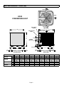
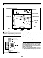
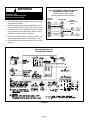
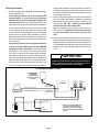
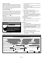
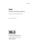
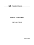
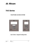
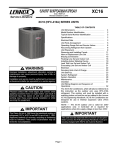
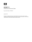
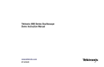
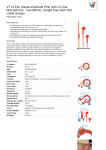
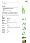
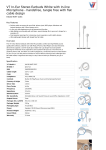
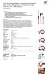
¤2000 Lennox Industries Inc INSTALLATION INSTRUCTIONS . Dallas, Texas HS32 SERIES UNITS CONDENSING UNITS 504,179M 2/2000 Supersedes 503,987M Litho U.S.A. Table of Contents HS32 Condensing Unit HS32 condensing units use R410A which is an ozone friendly HFC refrigerant. This unit must be installed with a matching indoor coil and line set as outlined in the Lennox Engineering Handbook. HS32 condensing units are designed for use in expansion valve systems only. They are not designed to be used with other refrigerant flow control devices. An expansion valve and filter drier approved for use with R410A have been shipped with the unit. These components must be installed prior to unit operation. HS32 CONDENSING UNIT . . . . . . . . . . . . . . . . . . . . . . . . . . 1 SHIPPING AND PACKING LIST . . . . . . . . . . . . . . . . . . . . . . 1 GENERAL INFORMATION . . . . . . . . . . . . . . . . . . . . . . . . . . 1 HS32 UNIT DIMENSIONS . . . . . . . . . . . . . . . . . . . . . . . . . . . 2 HS32 PARTS ARRANGEMENT . . . . . . . . . . . . . . . . . . . . . . 3 SETTING THE UNIT . . . . . . . . . . . . . . . . . . . . . . . . . . . . . . . . 3 ELECTRICAL . . . . . . . . . . . . . . . . . . . . . . . . . . . . . . . . . . . . . . 3 PLUMBING . . . . . . . . . . . . . . . . . . . . . . . . . . . . . . . . . . . . . . . . 5 FLUSHING EXISTING LINE SET AND INDOOR COIL . . 5 MANIFOLD GAUGE SET . . . . . . . . . . . . . . . . . . . . . . . . . . . . 7 LIQUID & SUCTION LINE SERVICE VALVES . . . . . . . . . . 7 LEAK TESTING . . . . . . . . . . . . . . . . . . . . . . . . . . . . . . . . . . . . 8 EVACUATION & DEHYDRATION . . . . . . . . . . . . . . . . . . . . . 8 START-UP . . . . . . . . . . . . . . . . . . . . . . . . . . . . . . . . . . . . . . . . 9 CHARGING . . . . . . . . . . . . . . . . . . . . . . . . . . . . . . . . . . . . . . . 9 SYSTEM OPERATION . . . . . . . . . . . . . . . . . . . . . . . . . . . . . 11 MAINTENANCE . . . . . . . . . . . . . . . . . . . . . . . . . . . . . . . . . . . 12 HS32 CHECK POINTS . . . . . . . . . . . . . . . . . . . . . . . . . . . . . 12 RETAIN THESE INSTRUCTIONS FOR FUTURE REFERENCE General Information These instructions are intended as a general guide and do not supersede national or local codes in any way. Authorities having jurisdiction should be consulted before installation. Shipping and Packing List 1 - Assembled HS32 condensing unit 1 - Drier (approved for use with R410A systems) 1 - Expansion valve (approved for use with R410A) Check unit for shipping damage. Consult last carrier immediately if damage is found. WARNING Improper installation, adjustment, alteration, service or maintenance can cause property damage, personal injury or loss of life. Installation and service must be performed by a qualified installer or service agency. IMPORTANT WARNING This product is matched with an indoor unit which contains fiberglass wool. Disturbing the insulation in the indoor unit during installation, maintenance, or repair will expose you to fiberglass wool. Breathing this may cause lung cancer. (Fiberglass wool is known to the State of California to cause cancer.) Fiberglass wool may also cause respiratory, skin and eye irritation. To reduce exposure to this substance or for further information, consult material safety data sheets available from address shown below, or contact your supervisor. Lennox Industries Inc. P. O. Box 799900 Dallas, TX 75379-9900 This unit must be matched with an indoor coil as specified in Lennox’ Engineering Handbook. Coils previously charged with R22 must be flushed. 02/00 $ 504,179M Page 1 $! HS32 Unit Dimensions -- Inches (mm) INLET AIR INLET HS32 CONDENSING UNIT COMPRESSOR AIR INLET ELECTRICAL INLETS AIR TOP VIEW C B SUCTION LINE INLET DISCHARGE AIR 4-1/2 (114) A LIQUID LINE INLET D J J H 2-3/4 (70) H 4-7/8 (22) 2 (51) 2-9/16 (65) 2 (51) G 1-3/8 (35) 4 (102) HS32 024 HS32-024 HS32-030, HS32-036 HS32-036, HS32-042 HS32 048 HS32-048 HS32 060 HS32-060 4 (102) E ACCESS VIEW Model No. F 6-1/16 (154) SIDE VIEW in. mm A 27-7/8 708 B 25-7/8 657 C 29-7/8 759 D 12-1/4 311 E 22-7/16 570 F 14-7/16 367 G 22-1/8 562 H 2-7/8 73 J 5-1/2 140 in. 30-7/8 32-1/8 34-1/16 12-3/4 26-5/8 18-5/8 28-1/8 3-7/8 7-1/2 mm 784 816 865 324 676 473 718 98 191 in. mm in. mm 34-7/8 886 40-7/8 1038 32-1/8 816 32-1/8 816 34-1/16 865 34-1/16 865 13-3/4 349 19-3/4 502 26-5/8 676 26-5/8 676 18-5/8 473 18-5/8 473 28-1/8 718 28-1/8 718 3-7/8 98 3-7/8 98 7-1/2 191 7-1/2 191 Page 2 HS32 Parts Arrangement TIME DELAY CONDENSER FAN (NOT SHOWN) TOP OF CABINET GROUND LUG RUN CAPACITOR CONTACTOR SUCTION VALVE AND GAUGE PORT TERMINAL BOX LIQUID LINE SERVICE VALVE AND GAUGE PORT COMPRESSOR LOW PRESSURE SWITCH HIGH PRESSURE SWITCH FIGURE 1 A - Slab Mounting Setting the Unit Refer to unit dimensions on page 1 for sizing mounting slab, platforms or supports. Refer to figure 2 for installation clearances. INSTALLATION CLEARANCES NOTE- 48” (1219mm) CLEARANCE REQUIRED ON TOP OF UNIT. *36” (914mm) When installing unit at grade level, install on a level slab high enough above grade to allow adequate drainage of water. Top of slab should be located so run-off water from higher ground will not collect around unit. B - Roof Mounting Install unit at a minimum of 4 inches above surface of the roof. Care must be taken to ensure weight of unit is properly distributed over roof joists and rafters. Either redwood or steel supports are recommended. Electrical 36” (914mm) *36” (914mm) *36” (914mm) In the U.S.A., wiring must conform with current local codes and the current National Electric Code (NEC). In Canada, wiring must conform with current local codes and the current Canadian Electrical Code (CEC). Refer to the furnace or blower coil installation instructions for additional wiring application diagrams and refer to unit rating plate for minimum circuit ampacity and maximum overcurrent protection size. *NOTE—One side must be 36” (914mm). Two sides may be 12” (305mm). FIGURE 2 3DJH WARNING HS32 and FURNACE (GAS OR ELECTRIC) THERMOSTAT CONNECTIONS Unit must be grounded in accordance with national and local codes. ELECTRIC SHOCK HAZARD. Can cause injury or death. (Some connections may not apply. Refer to specific thermostat and furnace.) 1 - Install line voltage power supply to unit from a properly sized disconnect switch. Typical Furnace 2 - Install room thermostat (ordered separately) on an inside wall approximately in the center of the conditioned area and 5 feet (1.5M) from the floor. It should not be installed on an outside wall or where it can be effected by sunlight, drafts or vibrations. POWER R W1 W2 Thermostat 1ST STAGE AUX. HEAT 2ND STAGE AUX. HEAT Y R W1 W2 Y COMPRESSOR COMMON G C COMMON 3 - Install low voltage wiring from outdoor to indoor unit and from thermostat to indoor unit. See figures 3 and 4 . FIGURE 3 4 - Ground unit at unit disconnect switch or to an earth ground. HS32 CONDENSING UNIT FIELD WIRING DIAGRAM YELLOW Page 4 HS32 LOW PRESSURE SWITCH YELLOW G INDOOR BLOWER C FIGURE 4 HS32 Condensing Unit HS32 COMMON BLACK Plumbing If the HS32 unit is being installed with a new indoor coil and line set, the plumbing connections should be made as outlined in this section. If an existing line set and/or indoor coil is going to be used to complete the HS32 system, refer to the following section which includes flushing procedures. Field refrigerant piping consists of liquid and suction lines from the condensing unit (sweat connections). Use Lennox L15 series line sets as shown in table 1 or use field-fabricated refrigerant lines. Refer to the refrigerant piping bulletin in the Lennox Unit Information Service Manual for proper size, type and application of field-fabricated lines. Plumbing Connections HS32 Matched with New Indoor Coil and Line Set If an existing indoor coil which was equipped with an RFCI metering device is being replaced, the liquid line must also be replaced prior to the installation of the HS32 unit. If refrigerant lines are routed through a wall, seal and isolate the opening so vibration is not transmitted to the building. NOTE - Line length should be no greater than 50 ft. (15.2m). Select line set diameters from table 1 to ensure oil return to the compressor. TABLE 1 REFRIGERANT LINE KITS 2 - Before making line set connections, use dry nitrogen to purge the refrigerant piping. This will help to prevent oxidation and the introduction of moisture into the system. 3 - Use silver alloy brazing rods (5 or 6 percent silver alloy for copper-to-copper brazing or 45 percent silver alloy for copper-to-brass or copper-to-steel brazing) which are rated for use with R410A refrigerant. Wrap a wet cloth around the valve body and the copper tube stub. Remove light maroon washers from service valves and shield light maroon stickers in order to protect them during brazing. Braze the line set to the service valve. 4 - Quench the joint with water or a wet cloth to prevent heat damage to the valve core and opening port. IMPORTANT-The tube end must stay bottomed in the fitting during final assembly to ensure proper seating, sealing and rigidity. 5 - Install the provided thermal expansion valve (approved for use with R410A refrigerant) in the liquid line at the indoor coil. 6 - Install the provided filter drier (approved for use with R410A refrigerant) in the liquid line as close as possible to the expansion device. Do not leave the drier uncapped for more than 10 to 15 minutes prior to brazing, evacuation and leak testing. Flushing Existing Line Set and Indoor Coil HS32 UNIT LIQUID LINE SUCTION LINE L15 LINE SETS -024, -030, -036 3/8 in. (10mm) 3/4 in. (19mm) L15-41 20 ft. - 50 ft. (6m - 15m) -042, -048 3/8 in. (10mm) 7/8 in. (22mm) L15-65 30 ft. - 50 ft. (9m - 15m) -060 3/8 in. (10mm) 1-1/8 in. (29mm) Field Fabricated IMPORTANT If this unit is being matched with an approved line set or indoor coil which was previously charged with R22 refrigerant, or if it is being matched with a coil which was manufactured before January of 1999, the coil and line set must be flushed prior to installation. Take care to empty all existing traps. Polyol ester (POE) oils are used in Lennox units charged with R410A refrigerant. Residual mineral oil can act as an insulator, preventing proper heat transfer. It can also clog the thermal expansion valve, reducing system performance and capacity. Failure to properly flush the system per the instructions below will void the warranty. WARNING Polyol ester (POE) oils used with R410A refrigerant absorb moisture very quickly. It is very important that the refrigerant system be kept closed as much as possible. DO NOT remove line set caps or service valve stub caps until you are ready to make connections. CAUTION This procedure should not be performed on systems which contain contaminants (Example: compressor burn out). Required Equipment Brazing Connection Procedure 1 - The end of the refrigerant line must be cut square and its internal shape must remain round. The line must be free of nicks or dents and must be deburred (I.D. and O.D.) You will need the following equipment in order to flush the existing line set and indoor coil: two clean R22 recovery bottles, an oilless recovery machine with a pump down feature, and two sets of gauges (one for use with R22 and one for use with the R410A). 3DJH Flushing Procedure 1 - Remove existing R22 refrigerant using the appropriate procedure below. If the existing outdoor unit is not equipped with shut-off valves, or if the unit is not operational AND you plan to use the existing R22 refrigerant to flush the system -- Disconnect all power to the existing outdoor unit. Connect the existing unit, a clean recovery cylinder and the recovery machine according to the instructions provided with the recovery machine. Remove all R22 refrigerant from the existing system. Refer to gauges after shutdown to confirm that the entire system is completely void of refrigerant. Disconnect the liquid and suction lines from the existing outdoor unit. If the existing outdoor unit is equipped with manual shut-off valves AND you plan to use NEW R22 refrigerant to flush the system -- Start the existing R22 system in the cooling mode and close the liquid line valve. Pump all of the existing R22 refrigerant back into the oudoor unit. (It may be necessary to bypass the low pressure switches to ensure complete refrigerant evacuation.) When the low side system pressures reach 0 psig, close the suction line valve. Disconnect all power to the existing outdoor unit. Refer to gauges after shutdown to confirm that the valves are not allowing refrigerant to flow back into the low side of the system. Disconnect the liquid and vapor lines from the existing outdoor unit. 2 - Remove the existing outdoor unit. Set the new R410A unit and follow the brazing connection procedure which begins on the previous page to make line set connections. DO NOT install provided R410A check/expansion valve at this time. Make low voltage and line voltage connections to the new outdoor unit. DO NOT turn on power to the unit or open the outdoor unit service valves at this time. 3 - Remove the existing refrigerant flow control orifice or thermal expansion valve before continuing with flushing procedures. The existing devices are not approved for use with R410A refrigerant and may prevent proper flushing. Use a field-provided fitting to reconnect the lines. IMPORTANT The line set and indoor coil must be flushed with at least the same amount of clean refrigerant that previously charged the system. Check the charge in the flushing cylinder before proceeding. FLUSHING CONNECTIONS INVERTED R22 CYLINDER (Contains clean R22 to be used for flushing) HS32 UNIT SUCTION LINE SERVICE VALVE EXISTING SUCTION LINE EXISTING LOW HIGH PRESSURE PRESSURE GAUGE MANIFOLD EXISTING LIQUID LINE LIQUID LINE SERVICE VALVE INDOOR COIL OPENED CLOSED TANK RETURN INLET DISCHARGE RECOVERY CYLINDER RECOVERY MACHINE FIGURE 5 Page 6 NOTE - The inverted R22 cylinder must contain at least the same amount of refrigerant as was recovered from the existing system. 4 - Remove the pressure tap valve cores from the HS32 unit’s service valves. Connect an R22 cylinder with clean refrigerant to the suction service valve. Connect the R22 gauge set to the liquid line valve and connect a recovery machine with an empty recovery tank to the gauge set. 5 - Set the recovery machine for liquid recovery and start the recovery machine. Open the gauge set valves to allow the recovery machine to pull a vacuum on the existing system line set and indoor coil. The valve is equipped with a service port. A schrader valve is factory installed. A service port cap is supplied to protect the schrader valve from contamination and serve as the primary leak seal. To Access Schrader Port: 1234- Remove access panel. Remove service port cap with an adjustable wrench. Connect gauge to the service port. When testing is completed, replace service port cap. Tighten finger tight, then an additional 1/6 turn. 6 - Invert the cylinder of clean R22 and open its valve to allow liquid refrigerant to flow into the system through the suction line valve. Allow the refrigerant to pass from the cylinder and through the line set and the indoor coil before it enters the recovery machine. To Open Liquid or Suction Line Service Valve: 7 - After all of the liquid refrigerant has been recovered, switch the recovery machine to vapor recovery so that all of the R22 vapor is recovered. Allow the recovery machine to pull a vacuum on the system. LIQUID LINE SERVICE VALVE (VALVE OPEN) 1 - Remove stem cap with an adjustable wrench. 2 - Use a service wrench with a hex-head extension to back the stem out counterclockwise until the valve stem just touches the retaining ring. INSERT HEX WRENCH HERE STEM CAP SERVICE PORT NOTE - A single system flush should remove all of the mineral oil from the existing refrigerant lines and indoor coil. A second flushing may be done (using clean refrigerant) if insufficient amounts of mineral oil were removed during the first flush. Each time the system is flushed, you must allow the recovery machine to pull a vacuum on the system at the end of the procedure. UNIT SIDE SERVICE PORT CAP 8 - Close the valve on the inverted R22 drum and the gauge set valves. Pump the remaining refrigerant out of the recovery machine and turn the machine off. FIELD SIDE SCHRADER VALVE LIQUID LINE SERVICE VALVE (VALVE CLOSED) RETAINING RING 9 - Use nitrogen to break the vacuum on the refrigerant lines and indoor coil before removing the recovery machine, gauges and R22 refrigerant drum. Reinstall pressure tap valve cores into HS32 service valves. SERVICE PORT INSERT HEX WRENCH HERE UNIT SIDE 10 -Install the provided expansion valve (approved for use with R410A refrigerant) in the liquid line at the indoor coil. SERVICE PORT CAP Manifold Gauge Set FIELD SIDE SCHRADER VALVE OPEN TO LINE SET WHEN VALVE IS CLOSED (FRONT SEATED) Manifold gauge sets used with systems charged with R410A refrigerant must be capable of handling the higher system operating pressures. The gauges should be rated for use with pressures of 0 - 800 on the high side and a low side of 30” vacuum to 250 psi with dampened speed to 500 psi. Gauge hoses must be rated for use at up to 800 psi of pressure with a 4000 psi burst rating. (VALVE FRONT SEATED) FIGURE 6 DANGER Do not attempt to backseat this valve. Attempts to backseat this valve will cause snap ring to explode from valve body under pressure of refrigerant. Personal injury and unit damage will result. Liquid & Suction Line Service Valves The liquid line and suction line service valves (figures 6 and 7) and gauge ports are accessible from inside the unit, behind the access panel. The service ports are used for leak testing, evacuating, charging and checking charge. STEM CAP 3 - Replace the stem cap. Tighten finger tight, then tighten an additional 1/6 turn. 3DJH To Close Liquid or Suction Line Service Valve: WARNING 1 - Remove the stem cap with an adjustable wrench. 2 - Use a service wrench with a hex-head extension to turn the stem clockwise to seat the valve. Tighten it firmly. Never use oxygen to pressurize refrigeration or air conditioning systems. Oxygen will explode on contact with oil and could cause personal injury. When using high pressure gas such as nitrogen for this purpose, be sure to use a regulator that can control the pressure down to 1 or 2 psig (6.9 to 13.8 kPa). 3 - Replace the stem cap. Tighten finger tight, then tighten an additional 1/6 turn. SUCTION LINE SERVICE VALVE (VALVE OPEN) INSERT HEX WRENCH HERE Using an Electronic Leak Detector STEM CAP 1 - Connect the high pressure hose of the manifold gauge set to the suction valve service port. (Normally, the high pressure hose is connected to the liquid line port, however, connecting it to the suction port helps to protect the manifold gauge set from damage caused by high pressure.) FIELD SIDE SCHRADER VALVE 2 - With both manifold valves closed, connect the cylinder of R410A refrigerant. Open the valve on the R410A cylinder (vapor only). UNIT SIDE 3 - Open the high pressure side of the manifold to allow R410A into the line set and indoor unit. Weigh in a trace amount of R410A. [A trace amount is a maximum of 2 ounces (57g) refrigerant or 3 pounds (31 kPa) pressure]. Close the valve on the R410A cylinder and the valve on the high pressure side of the manifold gauge set. Disconnect R410A cylinder. SERVICE PORT CAP SERVICE PORT SUCTION LINE SERVICE VALVE (VALVE CLOSED) RETAINING RING STEM CAP FIELD SIDE 4 - Connect a cylinder of nitrogen with a pressure regulating valve to the center port of the manifold gauge set. INSERT HEX WRENCH HERE 5 - Adjust nitrogen pressure to 150 psig (1034 kPa). Open the valve on the high side of the manifold gauge set in order to pressurize the line set and the indoor coil. SERVICE PORT (VALVE FRONT SEATED) 6 - After a short period of time, open a refrigerant port to make sure that an adequate amount of refrigerant has been added for detection (refrigerant requirements will vary with line lengths). Check all joints for leaks. Purge nitrogen and R410A mixture. Correct any leaks and recheck. SERVICE PORT CAP SCHRADER VALVE OPEN TO LINE SET WHEN VALVE IS CLOSED (FRONT SEATED) UNIT SIDE FIGURE 7 IMPORTANT Leak Testing Leak detector must be capable of sensing HFC refrigerant. After the line set has been connected to the indoor and outdoor units, the line set connections and indoor unit must be checked for leaks. WARNING Refrigerant can be harmful if it is inhaled. Refrigerant must be used and recovered responsibly. Failure to follow this warning may result in personal injury or death. Evacuation & Dehydration Evacuating the system of non-condensables is critical for proper operation of the unit. Non-condensables are defined as any gas that will not condense under temperatures and pressures present during operation of an air conditioning system. Non-condensables and water vapor combine with refrigerant to produce substances that corrode copper piping and compressor parts. Page 8 1 - Connect the manifold gauge set to the service valve ports as follows: low pressure gauge to suction line service valve; high pressure gauge to liquid line service valve. IMPORTANT - Compliant scroll compressors (as with any refrigerant compressor) should never be used to evacuate a refrigeration or air conditioning system. NOTE - A temperature vacuum gauge, mercury vacuum or thermocouple gauge should be used. The usual bourdon tube gauges are inaccurate in the vacuum range. 2 - Connect the vacuum pump (with vacuum gauge) to the center port of the manifold gauge set. 3 - Open both manifold valves and start vacuum pump. 4 - Evacuate the line set and indoor unit to an absolute pressure of 23mm (23,000 microns) of mercury or approximately 1 inch of mercury. During the early stages of evacuation, it is desirable to close the manifold gauge valve at least once to determine if there is a rapid rise in absolute pressure. A rapid rise in pressure indicates a relatively large leak. If this occurs, the leak testing procedure must be repeated. NOTE - The term absolute pressure means the total actual pressure within a given volume or system, above the absolute zero of pressure. Absolute pressure in a vacuum is equal to atmospheric pressure minus vacuum pressure. 5 - When the absolute pressure reaches 23mm (23,000 microns) of mercury, close the manifold gauge valves, turn off the vacuum pump and disconnect the manifold gauge center port hose from vacuum pump. Attach the manifold center port hose to a nitrogen cylinder with pressure regulator set to 150 psig (1034 kPa) and purge the hose. Open the manifold gauge valves to break the vacuum in the line set and indoor unit. Close the manifold gauge valves. WARNING Danger of Equipment Damage. Avoid deep vacuum operation. Do not use compressors to evacuate a system. Extremely low vacuums can cause internal arcing and compressor failure. Damage caused by deep vacuum operation will void warranty. 8 - When the absolute pressure requirement above has been met, disconnect the manifold hose from the vacuum pump and connect it to an upright cylinder of R410A refrigerant. Open the manifold gauge valves to break the vacuum in the line set and indoor unit. Close manifold gauge valves and shut off R410A cylinder and remove manifold gauge set. Start-Up 1 - Rotate fan to check for frozen bearings or binding. 2 - Inspect all factory and field-installed wiring for loose connections. 3 - Open liquid line and suction line service valves to release refrigerant charge (contained in condensing unit) into system. Replace and tighten caps. Use a back-up wrench on the suction and liquid valves when removing or replacing valve caps. 4 - To open suction valve, remove hex cap and turn valve stem fully open using an Allen (hex) wrench. To open liquid valve, remove cap and turn valve stem until it is fully open. NOTE - When replacing valve caps, the caps should be made finger tight and then tightened an additional 1/6th of a turn. 5 - Check voltage supply at the disconnect switch. The voltage must be within range listed on unit nameplate. If not, do not start equipment until the power company has been consulted and the voltage condition corrected. 6 - Set thermostat for a cooling demand, turn on power to blower and close the condensing unit disconnect switch to start. 7 - Recheck unit voltage with unit running. Power must be within range shown on unit nameplate. Check amperage draw of unit. Refer to unit nameplate for correct running amps. Charging 6 - Shut off the nitrogen cylinder and remove the manifold gauge hose from the cylinder. Open the manifold gauge valves to release the nitrogen from the line set and indoor unit. 7 - Reconnect the manifold gauge to the vacuum pump, turn the pump on and continue to evacuate the line set and indoor unit until the absolute pressure does not rise above .5mm (500 microns) of mercury within a 20-minute period after shutting off the vacuum pump and closing the manifold gauge valves. This system is charged with R410A refrigerant which operates at much higher pressures than R22. The expansion valve and liquid line drier provided with the unit are approved for use with R410A. Do not replace them with components designed for use with R22. This unit is NOT approved for use with coils which include metering orifices or capillary tubes. Processing Procedure Units are factory charged with the amount of R410A refrigerant indicated on the unit rating plate. This charge is based on a matching indoor coil and outdoor coil with 20 ft. (6.1m) line set. For varying lengths of line set, refer to table 2 for refrigerant charge adjustment. 3DJH TABLE 2 Liquid Line Set Diameter Ozs. per 5 ft. (grams per 1.5m) adjust from 20 ft. (6.1m) line set* 5/16 in (8mm) 2 ounces per 5 feet (57g per 1.5m) 3/8 in. (10mm) 3 ounces per 5 feet (85g per 1.5m) exists with some component in the system. Pressures higher than those listed indicate that the system is overcharged. Pressures lower than those listed indicate that the system is undercharged. A temperature/ pressure chart for R410A refrigerant is provided in table 5 for your convenience. Verify adjusted charge using the approach method. *If line length is greater than 20 ft. (6.1m), add this amount. If line length is less than 20 ft. (6.1m), subtract this amount. 4 - Outdoor temperature should be 60EF (16EC) or above. Use the same digital thermometer used to check outdoor ambient temperature to check liquid line temperature. Verify the unit charge using the approach method. The difference between the ambient and liquid temperatures should match values given in table 3. Refrigerant must be added to lower approach temperature and removed to increase approach temperature. Loss of charge results in low capacity and efficiency. IMPORTANT Mineral oils are not compatible with R410A. If oil must be added, it must be a polyol ester oil. The compressor is charged with sufficient polyol ester oil for line set lengths up to 50 ft. If line set lengths longer than 50 ft. will be required, add 1 ounce of oil for every additional 10 ft. of line set. Do not add any more than 7 oz. of oil. Copeland has approved Mobil EAL Arctic 22CC and ICI EMKARATE RL32CF for use with these compressors when oil must be added in the field. 5 - If the system is low on charge, R410A refrigerant must be added. Be aware of the R410A refrigerant cylinder. It will be light maroon-colored. Refrigerant should be added through the suction valve in the liquid state. Some R410A cylinders are equipped with a dip tube which allows you to draw liquid refrigerant from the bottom of the cylinder without turning the cylinder upside-down. The cylinder will be marked if it is equipped with a dip tube. If the system is void of refrigerant, the unit must be returned to the warehouse for exchange. Do not install a unit which has been delivered void of refrigerant. The following procedure is intended as a general guide and is for use on expansion valve systems only. For best results, indoor temperature should be 70EF (21EC) to 80EF (26EC). Be sure to monitor system pressures while charging. TABLE 3 APPROACH TEMPERATURES 1 - Record outdoor ambient temperature using a digital thermometer. 2 - Attach high pressure gauge set and operate unit for several minutes to allow system pressures to stabilize. Model Number Approach Temperature Liquid Line Temp. - Outdoor Ambient °F (°C) HS32-024 8 ± 1 (4.5 ± .5) HS32-030 8 ± 1 (4.5 ± .5) HS32-036 6 ± 1 (3.3 ± .5) HS32-042 9 ± 1 (5 ± .5) HS32-048 8 ± 1 (4.5 ± .5) 3 - Compare stabilized pressures with those provided in HS32-060 12 ± 1 (6.7 ± .5) table 4, Normal Operating Pressures. Minor variations NOTE - For best results, the same electronic thermometer in these pressures may be expected due to differences should be used to check both outdoor ambient and liquid in installations. Significant differences could mean that line temperatures. the system is not properly charged or that a problem TABLE 4 NORMAL OPERATING PRESSURES (Liquid ±10 and Suction ±5 psig) MODE TXV OUTDOOR EN COIL ENTERING AIR TEMP. °F (°C) Liquid Suction Liquid Suction Liquid Suction Liquid Suction Liquid Suction Liquid Suction 65 (18.3) 239 129 232 130 235 128 241 131 226 130 240 130 75 (23.9) 278 131 271 132 276 130 282 133 266 132 279 132 85 (29.4) 321 133 314 135 320 132 326 135 310 135 321 135 95 (35.0) 368 135 360 137 367 134 373 137 356 137 368 137 105 (40.6) 420 138 412 140 421 137 424 139 407 139 418 140 HS32-024 HS32-030 HS32-036 Page 10 HS32-042 HS32-048 HS32-060 TABLE 5 R410A Temperature/Pressure Chart Temperature °F Pressure Psig Temperature °F Pressure Psig Temperature °F Pressure Psig Temperature °F Pressure Psig 32 100.8 63 178.5 94 290.8 125 445.9 33 102.9 64 181.6 95 295.1 126 451.8 34 105.0 65 184.3 96 299.4 127 457.6 35 107.1 66 187.7 97 303.8 128 463.5 36 109.2 67 190.9 98 308.2 129 469.5 37 111.4 68 194.1 99 312.7 130 475.6 38 113.6 69 197.3 100 317.2 131 481.6 39 115.8 70 200.6 101 321.8 132 487.8 40 118.0 71 203.9 102 326.4 133 494.0 41 120.3 72 207.2 103 331.0 134 500.2 42 122.6 73 210.6 104 335.7 135 506.5 43 125.0 74 214.0 105 340.5 136 512.9 44 127.3 75 217.4 106 345.3 137 519.3 45 129.7 76 220.9 107 350.1 138 525.8 46 132.2 77 224.4 108 355.0 139 532.4 47 134.6 78 228.0 109 360.0 140 539.0 48 137.1 79 231.6 110 365.0 141 545.6 49 139.6 80 235.3 111 370.0 142 552.3 50 142.2 81 239.0 112 375.1 143 559.1 51 144.8 82 242.7 113 380.2 144 565.9 52 147.4 83 246.5 114 385.4 145 572.8 53 150.1 84 250.3 115 390.7 146 579.8 54 152.8 85 254.1 116 396.0 147 586.8 55 155.5 86 258.0 117 401.3 148 593.8 56 158.2 87 262.0 118 406.7 149 601.0 57 161.0 88 266.0 119 412.2 150 608.1 58 163.9 89 270.0 120 417.7 151 615.4 59 166.7 90 274.1 121 423.2 152 622.7 60 169.6 91 278.2 122 428.8 153 630.1 61 172.6 92 282.3 123 434.5 154 637.5 62 195.5 93 286.5 124 440.2 155 645.0 Discharge Thermostat System Operation Condensing unit and indoor blower cycle on demand from room thermostat. When thermostat blower switch is moved to ON position, indoor blower operates continuously. Compressor Time Delay (TD1) A compressor time delay is used to prevent compressor short cycling and to prevent the compressor from running backwards. When there is demand for a cooling cycle, the control delays compressor operation for about 5 minutes. Do not bypass the control. The Copeland Scroll compressor is equipped with a discharge line thermostat that removes power from the compressor when discharge temperatures reach approximately 280E F (138EC). The thermostat resets automatically at 130E F (54EC). CAUTION Danger of Equipment Damage. Do not bypass the discharge thermostat. 3DJH High Pressure Switch HS32 units are equipped with a high pressure switch that is located in the discharge line of the compressor. The switch (SPST, manual reset, normally closed) removes power from the compressor when discharge pressure rises above factory setting at 640 + 10 psi. Low Pressure Switch HS32 units are also equipped with a low pressure switch that is located in the suction line of the compressor. The switch (SPST, auto-reset, normally closed) removes power from the compressor when suction line pressure drops below factory setting at 40 + 5 psi. Filter Drier A drier is shipped with each HS32 unit. The drier must be field installed in the liquid line between the liquid line service valve and the expansion valve. This drier must be installed to ensure a clean, moisture-free system. A replacement drier is available as Lennox part no. 37L5201. Maintenance 1 - Clean and inspect condenser coil. Coil may be flushed with a water hose. 2 - Condenser fan motor is prelubricated and sealed. No further lubrication is needed. 3 - Visually inspect connecting lines and coils for evidence of oil leaks. 4 - Check wiring for loose connections. 5 - Check for correct voltage at unit (unit operating). 6 - Check amp-draw condenser fan motor. Unit nameplate _________ Actual ____________ . NOTE - If owner complains of insufficient cooling, the unit should be gauged and refrigerant charge checked. Refer to section on refrigerant charging in this instruction. Evaporator Coil 1 - Clean coil, if necessary. 2 - Check connecting lines and coils for evidence of oil leaks. 3 - Check condensate line and clean, if necessary. Indoor Unit 1 - Clean or change filters. 2 - Adjust blower speed for cooling. The pressure drop over the coil should be measured to determine the correct blower CFM. Refer to the unit information service manual for pressure drop tables and procedure. 3 - On belt drive blowers, check belt for wear and proper tension. WARNING Electric shock hazard. Can cause injury or death. Before attempting to perform any service or maintenance, turn the electrical power to unit OFF at disconnect switch(es). Unit may have multiple power supplies. At the beginning of each cooling season, the system should be checked as follows: 4 - Check all wiring for loose connections 5 - Check for correct voltage at unit (blower operating). 6 - Check amp-draw on blower motor Unit nameplate_________ Actual ____________. HS32 Check Points START-UP AND PERFORMANCE CHECK LIST Job Name Job Location Installer Unit Model No. Nameplate Voltage Date Job No. City City Serial No. State State Service Technician Amps: Supply Minimum Circuit Ampacity Maximum Overcurrent Protection Size Electrical Connections Tight? Indoor Filter Clean? S.P. Drop Over Evaporator (Dry) Indoor Blower RPM Discharge Pressure Suction Pressure Refrigerant Lines: Leak Checked? Properly Insulated? Outdoor Fan Compressor Supply Voltage (Unit Off) Outdoor Coil Entering Air Temp. Refrigerant Charge Checked? Outdoor Fan Checked? Service Valves Fully Opened? Service Valve Caps Tight? Voltage With Compressor Operating Calibrated? Page 12 Thermostat Properly Set? Level?