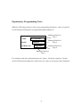
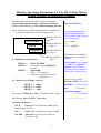
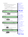
1
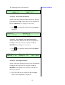
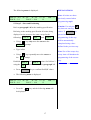
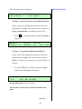
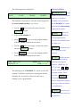
PROGRAMMING & OPERATING
INSTRUCTIONS
FOR
SCHILLING SM-110 portable
and SM-130 stand alone
MICRODOT MARKING SYSTEMS
Release 1 - September 7, 2000
Technical modifications reserved
Schilling Marking Systems GmbH
In Grubenaecker 1 D-78532 Tuttlingen
Release: 09/00
G:\Produkte\Bedienungsanltg\130-100\Englisch\Programming Operator Manual_ e.doc
++49 (0)7461 9472-0
++49 (0)7461 9472-20
www.marking-systems.de
[email protected]
Explanatory Programming Note:
While the following provides a step by step programming instruction – there is a general
overall strategy which applies to programming any marking text.
Marking Field No.1
Step 1
TYPE
DOT MATRIX
DATE
18/06/00
SERIAL NO.
Marking Field No.2
Step 2
SM123000
Marking Field No.4
Step 4
Marking Field No.3
Step 3
For example in the above illustration there are 4 steps – Each step comprises 7 menus
each of which must be addressed, (either enter new values or accept the values displayed.
4
Marking Operating Instructions For The SM 110 Dot Matrix
System Utilising an Illustrative Example.
The following describes the step by step procedure for
programming and operating the SM-110 and SM-130
(models without RS232 port) Dot Matrix Marking Systems
1.0 To illustrate the methods employed the overmarking of
an aluminium data plate is used. (Example only)
Marking Field No.1
Step 1
DOT MATRIX
18/06/00
SM123000
1.1 Marking Text Parameters
Marking Field No.2
Step 2
EXPLANATIONS:
For programming the Dot
Matrix Marking Machine
the text in the marking fields
must be classified …
Text - fixed
or
Text - variable
Marking Field No.4
Step 4
Marking Field No.3
Step 3
FIELD 1 = “DOT MATRIX”
FIELD 2 = Current date using DDMMYY
format.
FIELD 3 = “SM123000”
SM = Fixed prefix
Number= sequential serial no.
increment + 1
Text fixed can be letters or
numerals or a combination
of both.
Text variable can be a date
or a time or a sequential
number, but can only be
numerals. Letters cannot be
included in a variable field.
Hence in this example...
1.2 Character Size Height (Size H)
DOT MATRIX= Text fixed
DDMMYY = Text variable
FIELD 1 = 4MM
FIELD 2 = 2MM
FIELD 3 = 3MM
SM
1.3 Character Width (W) = 90% of standard width (100%)
1.4 Character Style, (FONT) = DIN 1451)
1.5 Other Parameters
1.51 D
= Space between characters = 60% of the
standard space (100%)
1.52 S
= Slant angle of characters required = 90º.
1.53 DIR = Direction of a line of text relative to
horizontal = 0º.
5
= Text fixed
Sequential Number
= Text variable
EXPLANATIONS:
2.0 Switching on.
With the machine off but connected to a 240v 50hz
Switching on:
electric supply and compressed air supply.
The values shown in this
•
menu are the specific
•
Switch power supply unit to on
details, (serial no. of the
Press red switch on the marking head unit to the on
position
machine and the release no.
of the software), of your
The following menu will be displayed….
S.R. No 00D0276
NNET NR. 01
machine.
RELEASE A 1.14
P33
CONFIG. 1008B1F6000
There are three levels of
Ignore values shown
•
Press the
Password Function:
ENTER
security.
key, the following is
displayed.
1st Level - “MARC”
allows a new marking
PASSWORD
layout to be programmed
and machine operation,
•
Type in “MARC”
•
Press
ENTER
(“MARC” may be
substituted for another
key.
password).
The following menu will be displayed….
DOT_ DIST = 0.2
MEM NO. = 0
PWM = 15
TIME =
P
2nd Level -“JOB” permits
machine operation for
existing program only
Ignore values shown – these relate only to the last
program carried out and are not relevant to programming
3rd Level -“MP456”
a new marking cycle.
permits the same as for level
•
Press
FN
1 but this cannot be
key, (repeatedly if necessary), until
changed.
the following menu is displayed
DOT_ DIST = 0.2
PWM = 15
MEMORY PROGRAMMING
P
“MEMORY
PROGRAMMING” is the
mode required to input a
•
Press
ENTER
key and the following menu
new marking cycle into
program memory.
is displayed.
6
The following menu should be displayed.
EXPLANATIONS:
= A discrete part
STEP
STEP No. 0
TEXT
MODE INSERT
DATE
NUMB
PWM= 15
of a marking text. - i.e.
“DOT MATRIX” = Step1
3.0 Step 1
3.1 Text Entry
DDMMYY
= Step 2
SMxxxx
= Step 3
xxx123000
= Step 4
Programming step 1 (Step 0 is displayed) now begins.
Note: FIELD 3 is made up
•
The cursor should be on the MODE
of two steps
•
Using the
displayed.
INSERT
•
Press
prompt.
arrow keys scroll until
is displayed
ENTER
,
STEP 1
STEP 0
is displayed.
MODE
Options:
key.
The cursor will move on to the TEXT
•
Note: For
prompt.
INSERT
Press
ENTER
key and the following menu
Or
is displayed.
CLEAR
Or
ERASE
Or
TEXT:
MODIFY
PWM
value displayed is
simply a reminder of a
•
Using
on the left hand side of the keyboard
select upper case, and the letter M appears on the top
left of the display.
•
previously programmed
value.
DATE
If a continuous
update is required
Type in “DOT MATRIX”.
-
Change is automatic
NUMB
Applies only if
a sequential number series is
required.
7
•
Press
ENTER
EXPLANATIONS:
key
(From previous menus)
The following menu is displayed.
If
SIZE H = 5.0
POS X = 3.0
W= 100 D = 100
POS Y = 24.0
S = 90
JJ
DIR = 0
is displayed
STEP 0
no previous values for have
been programmed. Hence
the only option at the mode
prompt is INSERT
.
3.2 Step 1 – Entering Text Sizes and Positioning
Refer to paragraph 1.0 for the marking specification
•
or
STEP 1
a higher step value is
Using
SIZE H
•
However, if
key only move the cursor to the
, (character height) prompt
displayed a marking cycle
already exists in program
memory – to insert new text
Type in 4.0 for the character height.
scroll using the
•
Using
•
Type in “90” for the percentage character width.
•
Using
•
Type in 60 for the percentage character spacing.
key move the cursor to W prompt .
key move the cursor to D
prompt .
keys until
CLEAR
is
displayed.
Press
ENTER
and then
ENTER again to confirm
this. Then proceed to insert
new text as described.
•
Using
•
Type in 90 for the standard slant.
•
Using
key move the cursor to S
prompt .
Caution: Use only the
key between entering
key move the cursor to DIR prompt .
values. If
ENTER
is
pressed mistakenly the
•
•
Type in 0 for the marking direction angle.
programming of this step
will be automatically
Using
key move the cursor to JJ
prompt.
completed using values
defined in the “DEFAULT
PARAMETERS” menu.
Note: Use of the escape key
at any time will abandon the
programming of the current
step.
8
•
Press
ENTER
key and the following menu is
EXPLANATIONS:
displayed.
POS X and POS Y values.
S = 0.1
S= 0.5
S= 1.0
POS X = 3.0
POS Y = 24.0
These relate to the marking
S = 5.0 0
start positions for FIELD 1,
FIELD 2, & FIELD 3 in
Note that the cursor is on the
•
S =0.1
relation to the bottom LH
prompt.
Now place the data plate firmly and symmetrically
in the marking area, (approx’ centre)
•
Using
extremity of the 110mm x
30mm marking area (for
SM-110) and 130x100mm
keys inch the
(for SM-130)
stylus from its parked position to FIELD 1 until the
Stylus Park
Position
stylus is directly above the bottom left hand corner.
Note values of
POS X
and
POS Y
x=0,
y=30
x=110,
y=30
110
TYPE
(SM-110)
30
DATE
x=0,
y=0
SERIAL No.
x=110,
y=0
Ideal position of mark
•
To establish final
POS X
to move the stylus until the
value use the
POS X
key
within its field.
value is
.DOT MATRIX
increased by 1mm.
1mm
1mm
•
To establish final
POS Y
to move the stylus until the
value use the
POS Y
key
value is
increased by 1mm.
XY movement of the stylus
is constantly measured and
•
Press
•
The stylus will return to its park position and the
following menu is displayed.
ENTER
Using the JJ function the
key.
displayed. To change the
step distance, e.g. S=0.5
when inching the stylus use
the
9
key.
The following menu is displayed
SIZE H = 4.0
POS X = 3.0
EXPLANATIONS:
W= 90
D = 60
POS Y = 24.0
S = 90
JJ
DIR = 0
NEEDLE: DOTS DIST
Is the distance between the
dots produced – i.e. for the
letter “T”
3.3 Step 1. - Stylus parameter settings
•
Press
0.1 to 5mm
variable
key only to display the following menu
NEEDLE: DOTS DIST = 0.2
PWM = 15
UPSTROKE TIME = 10
DIST = 1.0
Values selected:
UPSTROKE TIME
Variable 1-30msecs.
Effects…
i. Depth of mark
ii. Marking speed
iii.Clarity
DOTS DISTANCE = 0.2mm
UPSTROKE TIME = 10msec
PWM
= 15%
DIST
= 1mm
PWM
•
•
The cursor should be on
0.2
NEEDLE: DOTS DIST
is shown – since this is the value wanted no
Using
•
Type in “9”.
•
Using
•
15
. Dwell time – Duration
electrovalve is open.
Effects…
change is necessary.
•
i. Marking depth
key move cursor to UPSTROKE TIME
key move cursor to
%
PWM
prompt.
Is shown - since this is the value wanted no
ii.Marking speed
DIST
(1 – 14mm)
Setting memorandum for
distance of stylus from
change is necessary.
marking area–stylus height.
•
Using
•
Type in”2”.
key move cursor to
DIST
prompt.
Effects… Marking depth
i.e. Value for a light mark or
on soft materials = 1mm,
For a deep mark =14mm
10
•
Press
key until the next menu is displayed.
SPEED % =
FONT = MATRIX 7 x 5
MOVING 99
JUST = RIGHT
EXPLANATIONS:
MOVING
= % of max
nominal marking speed
3.4 Step 1. - Speed, Fonts and Justification
Values selected:
•
FONT
=Character style
MOVING = 80%
selection from standard
FONT
= DIN 1451
options.
JUST
= RIGHT
Press
key to move cursor to MOVING
JUST
prompt.
= Justification -
- direction in which
•
Type in “80”
•
Press
characters progress as they
key to move cursor to
FONT
prompt.
•
Using the
DIN 1451
•
Press
LEFT
or
arrow keys scroll until
is displayed.
key to move cursor to
JUST
i.e. If RIGHT is displayed
the characters will progress
to the right of the start
Using the
RIGHT
•
RIGHT
or
CENTRE
prompt.
•
are marked. Options are…
Press
arrow keys scroll until
is displayed.
key until the next menu is displayed.
11
selected point.
EXPLANATIONS:
The following menu will be displayed.
REPEAT = overmarking
of stylus – used to deepen
REPEAT = 1
MIRROR X = NO
DX = 0.0
DY = 0.0
MIRROR Y = NO
DIST = PROP
the mark.
This can be
repeated up to 9 times.
3.5 Special Effects
Values selected
REPEAT
=1
DX
= 0.0
DY
= 0.0
DX
= Repeat mark but
offset to give a shadow
effect horizontally.
MIRROR X = NO
MIRROR Y = NO
DIST
DY
= PROP
= Repeat mark but
offset to give a shadow
Since the selected values required above are being
effect vertically.
displayed on the menu no changes are required.
MIRROR X
•
=
Vertical
reflection of the image.
Press [ ENTER ] key to confirm all data for step 1,
and this menu is displayed once more.
MIRROR Y
STEP No. 1
TEXT
MODE INSERT
DATE
NUMB
PWM= 15
Programming step2 can now proceed, i.e. – FIELD No.2,
Horizontal
reflection of the image.
DIST
The programming of step1 is now complete.
=
= Spacing between
characters when offset is
used.
Options are:
DATE
Note: Menu will display step 1 indicating that one step
has already been programmed.
12
STAND = Standard space
Or
PROP = Proportional space
The following menu will be displayed
STEP No. 1
TEXT
EXPLANATIONS:
MODE INSERT
DATE
NUMB
PWM= 15
Date Formats:
There are several date
4.0 Programming Step 2 – Date.
formats from which to
4.1 Step 2 - Date Format entry.
choose.
•
DDMMYY
If INSERT
is not being displayed use the
keys to scroll through the options until it is.
•
MMDDYY
YYMMDD
Press
ENTER
key.
YYDDMM
The cursor will move on to the text prompt.
•
Press
key to move the cursor to the
DDMMYYYY
DATE
YYYYMMDD
prompt.
•
MMDDYYYY
YYYYDDMM
Press ENTER
key.
Y
YY
The following menu will be displayed
YYYY
DATE:
FORMAT
01/07/00
SEPARATOR = /
DDMMYY
HHMM(12hr)
HHMM(12hr am/pm)
Format selected:
DATE
HHMM(24hr)
(am/pm 12hr)HHMM
= DDMMYY
SEPARATOR
DD
= /
MM
•
With the cursor on the
the
FORMAT
prompt use
to scroll until DDMMYY
is
Separator Formats:
displayed.
Several options available
•
Press
key to move the cursor to the
SEPARATOR
prompt.
•
Type in the separator required -
•
Press
/ or – or + or [SPACE]
etc.
/
.
key to move to the next menu.
13
The following menu is displayed…
SIZE H = 4.0
POS X = 3.0
W= 90
D = 60
POS Y = 24.0
EXPLANATIONS:
S = 90
JJ
DIR = 0
4.2 Step 2 – Date Sizes and Positioning
Note all values are those previously entered when
programming step1.
Check paragraph 1.0 for the marking specification. All
values being displayed on the menu are valid except for
the following… SIZE H
•
Using
,
POS X
and POS Y
key only move the cursor to the
SIZE H
Caution: Use only the
prompt
key between entering
•
Type in 2.0
•
Using
the
values. If
key repeatedly move the cursor to
is
pressed mistakenly the
programming of this step
prompt.
JJ
ENTER
will be automatically
completed using values
defined in the previous step.
Now establish
` X
POS
and
POS Y values for
field no.2. Repeat the step by step using the “JJ”
function as described in paragraph 3.2.
Note: Use of the escape key
•
Press ENTER
•
The following menu is displayed.
at any time will abandon the
programming of the current
SIZE H = 2.0
POS X = 9.0
•
key to confirm final X,Y values.
W= 90
D = 60
POS Y = 14.0
Press the
step.
S = 90
JJ
DIR = 0
key and the following menu will
be displayed.
14
The following menu is be displayed.
NEEDLE: DOTS DIST = 0.2
PWM = 15
EXPLANATIONS:
UPSTROKE TIME = 10
DIST = 1.0
4.3 Step 2 – Date Stylus Parameters
All the values now displayed in these menus are the ones
programmed for step 1. Since these are also required for
step 2, (DDMMYY), no changes are necessary.
•
Press
key repeatedly until the following menu is
displayed.
SPEED % =
FONT = DIN 1451
MOVING 80
JUST = RIGHT
4.4 Step 2 – Date Speeds, Fonts and Justification
All the values now displayed are the ones programmed
for step 1. Since these are also required for step 2,
(DDMMYY), no changes are necessary.
•
Press
key repeatedly until the following menu is
displayed.
REPEAT = 1
MIRROR X = NO
DX = 0.0
DY = 0.0
MIRROR Y = NO
DIST = PROP
4.5 Step 2 – Date Special Effects
All the values now displayed in are the ones programmed
for step 1. Since these are also required for step 2,
(DDMMYY), no changes are necessary as no special
effects are required.
•
Press [ENTER] key to confirm all data for step 2,
and the following menu is displayed.
15
The following menu is being displayed.
STEP No. 2
TEXT
MODE INSERT
DATE
NUMB
EXPLANATIONS:
PWM= 15
Note: Menu will display
step 2 indicating that two
steps have already been
Programming step 2 is now complete. Step 3 (SM) can
programmed.
now be programmed.
5.0 Programming Step 3, Serial Number Prefix.
The serial no. consists of a
5.1 Step 3, Format Entry
•
If
fixed text portion, (SM)
INSERT is not being displayed use the
keys to scroll through the options until it is.
•
Press
ENTER
•
need to be considered
DATE
prompt.
separately. The fixed text
portion shall be considered
Press
key to move the cursor to the
prompt.
•
which starts at 123000 and
finishes at 123100. These
key.
The cursor will move on to the
and a sequential number
Press
ENTER
key.
The following menu will be displayed
TEXT:
Format selected:
TEXT
= SMxxxxxx
•
Type in “SM”.
•
Press
ENTER
key.
16
TEXT
first.
The following menu is displayed…
EXPLANATIONS:
Note: all values are those
SIZE H = 4.0
POS X = 3.0
W= 90
D = 60
POS Y = 24.0
S = 90
JJ
DIR = 0
previously entered when
programming step2.
5.2 Step 3 – Sizes and Positioning
Refer to paragraph 1.0 for the marking specification
Caution: Use only the
key between entering
Referring to the marking specification all values being
values. If
displayed on the menu are the same except for the
pressed mistakenly the
following… SIZE H
programming of this step
•
Using
,
and
POS
POS Y
key only move the cursor to the
SIZE H
ENTER
is
will be automatically
completed using values
prompt
defined in the previous step.
•
Type in 3.0
Note: Use of the escape key
•
Using
the
key repeatedly move the cursor to
programming of the current
prompt.
JJ
at any time will abandon the
step.
Establish `POS X
using the
JJ
and POS Y
values for field no.3
function as described in paragraph 3.2.
•
Press ENTER
•
The following menu is displayed.
SIZE H = 3.0
POS X = 9.0
•
key to confirm final X,Y values.
W= 90
D = 60
POS Y = 14.0
Press the
S = 90
JJ
DIR = 0
key and the following menu will
be displayed.
17
The following menu is displayed.
NEEDLE: DOTS DIST = 0.2
PWM = 15
EXPLANATIONS:
UPSTROKE TIME = 10
DIST = 1.0
5.3 Step 3 – Prefix Stylus Parameters
All the values now displayed are the same as the ones
programmed for step 2. Since these are also required for
step 3, (SM), no changes are necessary.
•
Press
key repeatedly until the following menu
is displayed.
SPEED % =
FONT = DIN 1451
MOVING 80
JUST = RIGHT
5.3 Step 3 – Speed, Character Style and Justification
All the values now displayed are the same as the ones
programmed for step 2. Since these are also required for
step 3, (SM), no changes are necessary.
•
Press
key repeatedly until the following menu
is displayed.
REPEAT = 1
MIRROR X = NO
DX = 0.0
DY = 0.0
MIRROR Y = NO
DIST = PROP
5.4 Step 3 – Special Effects
All the values now displayed are the same as the ones
programmed for step 2. Since these are also valid for
step 3. no changes are necessary as no special effects are
required.
•
Press [ENTER] key to confirm all data for step 3,
and the following menu is displayed.
18
The following menu is displayed
STEP No. 3
TEXT
EXPLANATIONS:
MODE INSERT
DATE
NUMB
PWM= 15
Programming step 3 is now complete. Step 4, (123000
– the sequential number), can now be programmed.
Note: Menu will display step 3 indicating that three steps
have already been programmed.
6.0 Programming Step 4 – Sequential Number
6.1 Step 4 – Format Entry
•
= Direction in
DIR
If
INSERT is not being displayed use the
which to count.
keys to scroll through the options until it is.
•
•
i.e.
Press
ENTER key.
The cursor will move on to the
Press
BACK = Down
TEXT
key to move the cursor to the
prompt.
NUMB
S
Press ENTER
key.
E
The following menu will be displayed
COUNTER
S=0000000
= Counter start value
or start of sequential no.
prompt.
•
AHEAD = Up
0000
E=9999999
= Counter end value
or end of sequential no.
DIR = AHEAD
CHAR = 0 FIELD LEN =4
CHAR
Format selected:
= Character to
be inserted in unused
COUNTER = N/A (Not modifiable)
DIR
= AHEAD
S
= 123000
E
= 123100
CHAR
=0
spaces, (blank, “0” or “-“)
FIELD LEN
= number
of digits in the sequential
number
FIELD LEN = 6
19
As before the following menu is displayed
COUNTER
S=000000
0000
E=999999
Ensure the cursor is on the
•
If not use the
•
Using
EXPLANATIONS:
DIR = AHEAD
CHAR = 0 FIELD LEN =4
prompt.
DIR
keys until it is.
scroll until
AHEAD
is
displayed.
•
Use
•
Type in”123000”
•
Use
to move the cursor to the
S
prompt.
Note: In this example it is
proposed that 100
identification plates are to
to move the cursor to the
E
prompt.
be marked and that the
number shall increment by
•
Type in “123100”.
•
Use
+1 from 123000 to 123100.
to move the cursor to the
CHAR
prompt.
•
Type in ”0”.
•
Use
to move the cursor to the
FIELD LEN
prompt.
•
Using
•
Press
scroll until “6” is displayed.
ENTER
and the following menu will be
displayed.
SIZE H = 3.0
POS X = 3.0
W= 90
D = 60
POS Y = 24.0
S = 90
JJ
20
DIR = 0
As before the following menu is displayed…
SIZE H = 3.0
POS X = 3.0
W= 90
D = 60
POS Y = 24.0
EXPLANATIONS:
S = 90
JJ
DIR = 0
Note: all values are those
previously entered when
programming step 3.
6.2 Step 4 – Sequential number size and positioning
Referring to the marking specification in paragraph 1. all
“AUTO” explained: Since
values being displayed on the menu are valid except for ,
the sequential part of the
a POS X
serial no. is on the same line
and
POS Y
which will be placed using the
“AUTO” function.
as prefix ”SM” and follows
•
Position the cursor on the
•
Press
to select
•
Press
key repeatedly until the following menu
POS X
prompt.
on without spacing there is
no need to redefine “POS
AUTO
X” and “POS Y” values.
.
A feature exists called
“AUTO” which
is displayed.
automatically places a text
immediately after the
NEEDLE: DOTS DIST = 0.2
PWM = 15
UPSTROKE TIME = 10
DIST = 1.0
6.3 Step 4 – Sequential Number Stylus Parameters
All the values now displayed are the same as the ones
programmed for step 3. Since these are also required for
step 4, (Sequential no.), no changes are necessary.
previous one
Caution: Use only the
key between entering
values. If
ENTER
is
pressed mistakenly the
programming of this step
•
Press
key repeatedly until the following menu is
will be automatically
completed using values
displayed.
defined in the previous step.
Note: Use of the escape key
at any time will abandon
the programming of the
current step.
21
The following menu is displayed
SPEED % =
FONT = DIN 1451
EXPLANATIONS:
MOVING 80
JUST = RIGHT
6.4 Step 4 – Speed, Character Style and Justification.
All the values now displayed are the same as the ones
programmed for step 3. Since these are also required for
step 4, (Sequential no.), no changes are necessary.
•
Press
key repeatedly until the following menu is
displayed.
REPEAT = 1
MIRROR X = NO
DX = 0.0
DY = 0.0
MIRROR Y = NO
DIST = PROP
6.5 Step 4 – Sequential Number Special Effects
All the values now displayed are the same as the ones
programmed for step 3. Since these are also valid for
step 4. no changes are necessary as no special effects are
required.
•
Press [ENTER] key to confirm all data for step 4,
and the following menu is displayed.
STEP No. 4
TEXT
MODE INSERT
DATE
NUMB
PWM= 15
Programming step 4 is now complete.
The machine is now ready to mark the identification
plate.
(Cont’d)
22
7.0 Typical Machine Cycle
EXPLANATIONS:
7.1 Component Setting
•
Place the component under the stylus in the same
position as before.
•
Physically check the stylus height above the
component and check that it is the same as the value
entered under DIST
in the “Stylus Parameter
Menus”, (i.e. 2.0mm). After any adjustment check
that the marking unit is firmly secured.
7.2 Dummy - Test Marking Run
A facility exists to check the stylus movements
programmed without marking the component.
•
Press the
ESC
key to display the following
menu.
DOT_ DIST = 0.2
MEM NO. = 0
•
Press the
PWM = 15
TIME =
ALT
P
key once. This will turn off the air
supply to the stylus and the letter
P
shown on
the right hand side of the display will become, p
(lower case), confirming that the air is turned off.
•
Press the “START” button and the stylus will
proceed to simulate the marking cycle by following
the path programmed but without marking the
component.
23
7.3) Component Marking
EXPLANATIONS:
Having ensured that the stylus travels correctly around the
marking area the component is now ready to be marked.
•
Press the
key once more to turn on the air
ALT
supply. The letter
P
will be displayed once
more.
•
Making sure that the component is firmly in place,
press the “START” button to activate the marking
cycle.
The
Once the marking cycle is completed and the stylus has
TIME
prompt on
the left of the display shows
returned to its home position the following menu will be
the total marking cycle
displayed.
time to mark the
component.
DOT_ DIST = 0.2
MEM NO. = 0
PWM = 15
P
TIME = 11.2 s
Also shown is the prompt
MEM NO. = 0 indicating
that the program is still in
program memory, (No. 0),
8.0 Saving and loading a marking cycle in file memory.
•
Press
FN
and has not been saved.
key, (repeatedly if necessary), until
the following menu is displayed
DOT_ DIST = 0.2
PWM = 15
MEMORY MANAGEMENT
P
MEMORY MANAGEMENT
This menu is where all the
values for the parameters in
•
Press
ENTER
key and the following menu is
displayed.
each menu which are
necessary for a complete
marking cycle are stored
and retained in memory for
future use.
24
The following menu is displayed
MEMORY NO. = 6
SAVE
LOAD
NAME =
ERASE
EXPLANATION:
MEMORY NO. =
MODIFY
is the
number of the next available
memory in which the
The machine will propose to save the current program in
marking cycle parameters
the next available memory, (e.g. No.6)
for “EXAMPLE 1” can be
stored. Up to 100 marking
•
Use the
key to move the cursor on to the
NAME
cycles can be stored.
prompt.
allows the
NAME
•
Type in “EXAMPLE 1”.
•
Press
ENTER
user to name the marking
key to save the program and the
following menu is displayed once more.
cycle program which
provides easy identification
for future use.
•
Use the
key, if necessary, to move the cursor
on to the
SAVE
SAVE
prompt.
Allows the user
save a program in file
•
Press
ENTER
key to save the program and the
memory.
following menu is displayed once more.
LOAD
Allows the user
load a program from file
DOT_ DIST = 0.2
MEM NO. = 6
PWM = 15
P
TIME = 11.2 s
memory into program
memory, (MEM NO. 0).
E.G. Use the
The marking cycle “EXAMPLE 1” is now saved in file
keys to select the desired
memory. It will also remain active in program memory,
program number. Then
(Memory No. 0), until it is cleared or until a new
press the
marking cycle is programmed.
The program chosen will
ENTER
key.
then be loaded into program
memory to allow operation
or modification.
ERASE
allows the user
to erase a program stored in
file memory.
25
9.0 Other facilities available using the
FN
key
EXPLANATIONS:
Several other useful facilities are available. These are…
MEMORY VISUALISATION
9.1 Memory Visualisation
This menu allows a user to view the marking cycles
This displays on the LCD
currently stored in file memory.
screen all previous job
•
cycles stored in memory.
Press
key, (repeatedly if necessary), until
FN
Note that the names of the
the following menu is displayed
marking cycles currently
DOT_ DIST = 0.2
PWM = 15
MEMORY VISUALISATION
•
P
their corresponding memory
number. Also note that the
Press
key and the following menu is
ENTER
contents of the steps
displayed – entries are examples only
MEMORY NO. = 6
STEP = 4
•
stored change along with
contained in each job cycle
can also be viewed.
NAME = EXAMPLE 1
With the cursor on
MEMORY NO. =
use the
arrow keys to scroll through the marking
cycles stored in file memory.
•
Press
key to return to the previous menu
ESC
DEFAULT PARAMETERS
9.2 Default Parameters
This menu allows a user to view the factory settings
If, during the “MEMORY
which is used for parameter values not modified in
PROGRAMMING” of
programming.
specific job cycles certain
•
Press
FN
key, (repeatedly if necessary), until
values have been ignored
the values contained within
the following menu is displayed
this menu will prevail.
DOT_ DIST = 0.2
PWM = 15
DEFAULT PARAMETERS
P
These are values preprogrammed at the factory,
•
Press
ENTER
key and the following menu is
displayed.
26
(factory settings).
These factory settings, however, may be changed to your
own values using this menu.
EXPLANATIONS
LANGUAGE: ENGLISH
The following menus is displayed…
This allows the choice of the
following languages.
SIZE H = 4.0
POS X = 3.0
•
W= 90
D = 60
POS Y = 24.0
Use the
S = 90
JJ
DIR = 0
key to move the cursor on through the
prompts, changing if required using the
ITALIAN
ENGLISH
SPANISH
GERMAN
keys or typing in actual values.
FRENCH
The following menus are also displayed as before
NEEDLE: DOTS DIST = 0.2
PWM = 15
UPSTROKE TIME = 10
DIST = 1.0
KEYS
allows two
variations of key operation
when they are held down
continuously:
and
SPEED % =
FONT = MATRIX 7 x 5
MOVING 99
JUST = RIGHT
and
CONT = Character repeat
SING = Single character
BUZZER: YES
REPEAT = 1
MIRROR X = NO
DX = 0.0
DY = 0.0
MIRROR Y = NO
DIST = PROP
allows
the keyboard to confirm a
key operation with a bleep.
However the following menus are also displayed
LANGUAGE =ENGLISH KEYS = CONT
UNIT OF MEASURE DIST= MM
Options are YES or NO
BUZZER=YES
MEASURE: MM allows
the common unit of measure
and
END MARKING TIME
REMOTE START
to be millimetres or inches
= 500MSEC
= VARIATION
REMOTE START
and
HOURS
29/06/2000
This allows the possibility
14:43:59
DAYS = THURSDAY
to operate the machine by a
momentary signal, (i.e.
Continue to press the
through the prompts. Press
key repeatedly to move
ESC
to exit the
“DEFAULT PARAMETERS” menu.
button push) or by a latched
signal, (i.e The start switch
must be constantly pressed).
Options are YES or NO.
27
9.3 Diagnostic Function
EXPLANATIONS:
This menu allows a user to test the machine for correct
operation of the display, the keyboard, stylus coverage of
programmed sequence of
signals.
Press
Tests the
display segments using a
the marking area and also checks input and output
•
DISPLAY
FN
character displays.
key, (repeatedly if necessary), until
KEYBOARD
the following menu is displayed
Checks
that all the keys on the
DOT_ DIST = 0.2
PWM = 15
DIAGNOSTIC
P
keyboard display their
appropriate character or
•
Press
ENTER
key and the following menu is
perform their correct
function.
displayed.
IN/OUT
DIAGNOSTIC FUNCTION:
DISPLAY KEYBOARD IN/OUT AREA TEST SERIAL
allows the
facility to check the START
and STOP input signals and
•
Use the
key to move the cursor through the
prompts. Press the
ENTER
key to perform any
also the Cycle and End
Cycle outputs available at
the 24v d.d. interface.
of the tests.
•
Press the
ESC
key at any time to abort a test.
•
Press the
ESC
key again to return to the previous
AREA TEST
Tests the
movement of the stylus
menu.
within the marking araea.
The stylus travels around
the extreme limits of the
DOT_ DIST = 0.2
MEM NO. = 0
PWM = 15
P
TIME = 11.2 s
marking area and back to its
home position again.
SERIAL
Checks the
RS232 interface, (If fitted),
for correct operation and
signal transmission to a
computer, (if connected).
28
10.0 Memory Reset
EXPLANATIONS:
In the event of a malfunction or to use the marking unit for a
completely different application, it can be useful to reset the
memory. To do this….
•
Switch the marking machine on whilst depressing the
SPACE
Note: Resetting the memory
key.
•
The marking unit starts to count up to 32 then stops.
will result in the loss of all
•
Switch off the marking unit and, after a few seconds,
stored marking cycle data
switch it on again.
and the default values
The marking machine will now be set as it was released from
programmed at the factory
the factory.
will be restored.
11.0 Battery Backup
The main program is permanently stored on an EPROM. The
marking cycles and their different parameters are stored on
in RAM memory which is protected by a nickel cadmium
battery when switched off. The battery has 3 months life if
the machine is permanently switched off.
29
Recommended Settings For Different Marking Requirements
The following is a general guide to the settings required for different marking requirements,
when using the Ø 3 mm Light Needle Kit.
Deep Marking
Stylus
Height
12-14mm
Stylus
Speed
--
Points
Distance
0.1 mm
Air*
Pressure
6 – 7 Bar
Upstroke
Time
15 msec
PWM
(Dwell)
30
Clear Marking
1 mm
50%
0.2 mm
4 – 5 Bar
10 msec
8 - 10
Fast Marking
2 –3 mm
99%
0.4 mm
--
10 msec
--
Fine Marking
1 mm
50%
0.2mm
4 – 5 Bar
8 - 10
* Air Pressure also dependent upon material being marked.
Notes:
Matrix 7 x 5 will always produce characters 7 dots high by 5 dots wide regardless of the
value entered for points distance, (DOTS DISTANCE).
The most pronounced effects upon marking depth are produced by increasing the stylus
height, (maximum 12 – 14mm), and increasing air pressure, (maximum 7 Bar).
For very fine marking fine tuning is successfully achieved by altering the stylus height above
a test component during the marking cycle.
30