1
VERTICAL
(VOLTAGE)
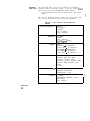
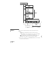
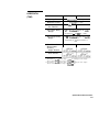
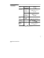
Specifications* * * *
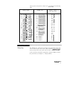
Channels
Bandwidth (- 3dB)’
dc-coupled
ac-coupled
Transition Time
(10% to 90%)
Deflection Factor
(full scale=8 div)
Resolution
(% of full scale)
2
Real-time
Repetitive
dc to 250 MHz
1 0 Hz to 250 MHz
dc to 500 MHz
1 0 Hz to 500 MHz
See “Operating
Characteristics”
700 ps
I
1 mV/div to 5 Vldiv continuous
8 bits to 25 MHz (0.4%),
7 bits to 100 MHz (0.8%),
6 bits to 250 MHz (1.6%),
6 bits (1.6%),
8 bits with averaging
to 500 MHz (0.4%)
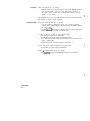
DC Gain Accuracy
22% of full-scale**
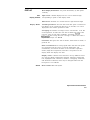
DC Offset Accuracy
~1.5% of setting ~0.2 div***
DC Measurement
Accuracy
single data point
between data
points on the
same waveform
DC Offset Range
Input Coupling
Maximum Safe
Input Voltage
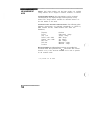
*Gain Act. c Offset Act. + Resolution
?Gain Act. ? 2 x Resolution
t.
+200 mV (1 mV/div to 4 mV/div)
k1 V (5 mV/div to 49 mV/div)
+lO V (50 mV/div to 499 mV/div)
240 V (500 mV/div to 5 Vidiv)
ac/dc!dc-50
Qlgnd
+40 Volts @I 1 MQ (dc +peak ac),
5 Vrms @ 50 R
Note
All voltages in table correspond to a 1:l attenuation setting. Ifa 1O:l
probe is attached, multiply all voltages by ten. The HP 10033A h a s a
maximum voltage of 2200 V
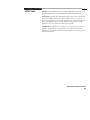
* Bandwidth for settings 1 mV/div to 4 mV/div is reduced to 150 MHz.
** When calibrated to probe tip using the front panel calibration source.
Applies to major ranges (5 mV/div, 10 mV/div, 20 mV/div, 50 mV/div,
100 mvldiv, 200 mV/div, 500 mV/div, 1 Vldiv, and 2 Vldiv). All continuous
settings between these ranges are 23% of full-scale. All settings between
1 mV and 4 mV/div are *4% of full-scale.
*** Increases to 20.4 divisions at 5 mVldiv to 9 mV/div, and of: 1 division
below 5 mV/div.
**** Applies for temperature ranges k5O C from point of last software calibration.
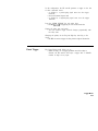
Specifications/Characteristics
15-2
(. j
j