1
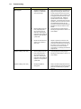
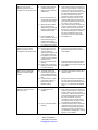
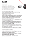
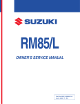
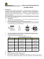
INSTALLATION & MAINTENANCE BULLETIN RM IMPERIAL & METRIC INTRODUCTION The Romet rotary meter is suitable for the measurement of most clean, dry gases. The installation of an upstream filter or, at the very least, a 200 mesh strai ner (e.g. Romet Tee Screen) will protect the meter from contaminants in the gas stream and permit accurate measurement. The meter is not suitable for the measurement of liquids. Consult the factory if any co rrosive gases (i.e. sour or sewer gases) are present, since these gases may have adverse effects on the mete r. Meters specifically constructed for these applications are available. The maximum allowable operating pressure (MAOP) of 175 psig or 12 bar and flow rating (Qmax) for each meter is indicated on the serial plate and should not be exceeded. Although ruggedly constructed, the Romet meter is a precision measuring instrument. 1.0 Pre-installation 1.1 Inspect the meter for any damage which may have occurred during transportation and handling. Consult the factory if the meter has been damaged. 1.2 Remove the sealing plugs or caps from the inlet and outlet port of the meter. 1.3 Ensure that all foreign material and scale hav e been removed from the meter station piping and that the mounting flanges are the correct distance (FL) apart, aligned with each other and level (maximum of 1/16" per foot or 5mm per meter in all directions). INLET FL Meter Model RM1000-RM5000 RM7000-RM23000 RM30-RM140 RM200-RM650 6 15/16" 9 11/16” 176 mm 246 mm METER METER FL INLET LEVEL LEVEL VERTICAL 1.4 1.5 The meter can be installed in either the horizontal or vertical position. The vertical position is the recommended installation since contaminants are more easily expelled from the meter, reducing the potential for internal wear or damage to the meter. Check that the correct hardware is available as per Table 1.0 TABLE 2.0 2.1 2.2 2.3 HORIZONTAL METER MODEL FLANGE RM1000-RM1500 RM30-RM40 ANSI 150 2” Flat Face RM2000-RM3000 RM55-RM85 ANSI 150 2” Flat Face RM5000-RM7000 RM140-RM200 ANSI 150 3” Flat Face RM11000-RM23000 RM300-RM650 ANSI 150 4” Flat Face 1.0 HARDWARE SPECIFICATION TABLE BOLTS 5/8”-11 x 1.5” long Hex Head, SAE Grade 5 Steel, Zinc Plated (8 Required) 5/8”-11 x 1.75” long Hex Head, SAE Grade 5 Steel, Zinc Plated (8 Required) 5/8”-11 x 2” long Hex Head, SAE Grade 5 Steel, Zinc Plated (8 Required) 5/8”-11 x 2.5” long Hex Head, SAE Grade 5 Steel, Zinc Plated (16 Required) WASHERS Flat; Steel; Zinc Plated (8 Required) Flat; Steel; Zinc Plated (8 Required) Flat; Steel; Zinc Plated (8 Required) Flat; Steel; Zinc Plated (16 Required) GASKETS ANSI 150 2” Full Face x 1/16” thick Compressed Fiber (2 Required) ANSI 150 2” Full Face x 1/16” thick Compressed Fiber (2 Required) ANSI 150 3” Full Face x 1/16” thick Compressed Fiber (2 Required) ANSI 150 4” Full Face x 1/16” thick Compressed Fiber (2 Required) Installation Install the meter using the hardware as specified in Table 1.0. Tighten the flange bolts to a torque of 20 ft-lbs (27 Nm). Fill the thrust cover, magnetic housing (RM2000-RM23000/RM55RM650) and module with approved meter oil (see section 2.5) to midway within the sight glass. In the case of a module with a counter (STD CTR, DCID, TC, 2.4 TCID), fill to the line on the counter dial plate. Depending on the meter model and mounting position (hor izontal or vertical), the required volume of oil will be different. Refer to table 2.0 to obtain the appropriate oil volumes. Note: Side reading STD CTR meters require an oil volu me for the module of 4.2 oz/120ml. In the case of ECM2, use the oil volumes for the magnetic housing and thrust cover for the applicable size TC meter. The ECM2 module being electronic does not require oil. TABLE 2.0 OIL VOLUME REQUIREMENTS (Imp oz / ml) METER MODEL RM1000-RM1500 RM30-RM40 RM2000-RM5000 RM55-RM140 RM7000RM23000 RM200-RM650 2.5 STD CTR, STD ID & DCID HORIZONTAL VERTICAL Module 2.5oz/70ml Module 6.3oz/180ml Magnetic Magnetic Housing N/A Housing N/A Thrust Thrust Cover 0.9oz/25ml Cover 2.1oz/60ml Module 6.3oz/180ml Module 6.3oz/180ml Magnetic Magnetic Housing 2.3oz/65ml Housing 3.5oz/100ml Thrust Thrust Cover 0.9oz/25ml Cover 2.5oz/70ml Module 4.2oz/120ml Module 4.2oz/120ml Magnetic Magnetic Housing 3.5oz/100ml Housing11.6oz/330ml Thrust Thrust Cover 1.4oz/40ml Cover 8.8oz/250ml TC & TCID HORIZONTAL VERTICAL N/A N/A Module 5.6oz/160ml Magnetic Housing 2.3oz/65ml Thrust Cover 0.9oz/25ml Module 8.1oz/240ml Magnetic Housing3.4oz/100ml Thrust Cover 1.4oz/40ml Module 8.8oz/250ml Magnetic Housing 3.5oz/100ml Thrust Cover 2.5oz/70ml Module 20.6oz/570ml Magnetic Housing11.6oz/330ml Thrust Cover 8.8oz/250ml An approved meter oil is available from Romet in one litre plastic bottle. Substitute oils should have a 60-65 SSU or ISO 10-15 at 100 oF or 38oC and a pour point of -40 oF/oC. The use of non-approved oil, without Romet's prior consent, may void the warranty. The approved oil for use with Romet meters is Shell Tellus R-10. 3.0 Post installation 3.1 Turn the gas supply on slowly (two seconds per 15 psig or 100 kPa maximum), checking constantly for leaks. Turning the gas supply on too quickly can overspeed and possibly damage the meter. 3.2 The flow rate of the meter should be checked to insure that the meter is correctly sized for the application and that the rated capacity (Qmax) is not being exceeded. The rated capacity (Qmax) is indicated on the serial plate that is located on the thrust cover. After installing the meter, the customer’s total gas load should be turned on to ens ure that the meter is sized correctly for the maximum flow rate. By measuring the number of seconds that the instru ment drive or right hand uncorrected counter wheel takes to complete one rota tion, the meter can be “clocked” to calculate the actual flow rate, using the formula below: ACTUAL VOLUME PER HOUR = TEST VOLUME x 3600 ROTATION TIME Test volume - Volume of gas (CF or m 3) for one complete revolution of the instrument drive or right hand wheel of the uncorrected counter. VOLUME/REVOLUTION METER RM1000-RM1500 10 CF RM2000-RM11000 10 CF / 100 CF RM16000-RM23000 100 CF RM30-RM85 0.1 m3 RM140-RM650 1.0 m3 Rotation time - The time in seconds for one complete revolution of the instrument drive or right hand wheel of the uncorrected counter. 4.0 Maintenance The meter oil should be clear and at the correct f ill levels (refer to section 2.4). Under normal operating conditions, the oil should be inspect ed every 5-10 years and changed or “topped up” as required. The change period will vary with the cleanliness of the gas being measured. Pressure access plugs are offered, as an option to permit o il filling and draining while the meter is pressurised and operating. If the meter is running abnormally "slow" or has stopped due to contamination from the gas stream, flush and/or service the meter per the Romet Shop Manual . Always drain all of the oil from the before removing the meter from the installation to prevent the oil from entering the measurement chamber during handling. After completing the servicing of t he meter, a differential pressure or proof test should be performed to ensure that the meter is clean and in good operating condition. 5.0 Troubleshooting TROUBLE Meter stopped POSSIBLE CAUSE REMEDY 1. Obstruction jamming the impellers (i.e. weld bead, stone, tap shaving) 1. 2. Mounting flanges have not been properly aligned or are not at the correct FL dimension, deforming the meter body and causing the impellers to jam against the cylinder wall. 2. 3. Mechanical instrument has seized on an instrument drive meter 3. Repair or replace the instrument. The recommended maximum torque that an instrument should transmit to the drive of the meter is 4 in oz or 0.004 Nm. The instrument drive module should be inspected for any damage per the Romet Shop Manual. Impellers rubbing, meter noisy 4. Mounting flanges have not been properly aligned or are not at the correct FL dimension, deforming the meter body and causing the impellers to rub against the cylinder wall. 4. Correctly align the mounting flanges, following the specifications in section 1.3 of this bulletin. Impellers rubbing; meter noisy 5. Damaged impellers or timing gears 5. Refer to the Romet Shop Manual for the proper procedure for inspecting the meter pressure and addressing any possible damage. Shut off the gas supply to the meter and purge the line of any gas. Remove the access plug from the thrust cover of the meter and insert a clean screwdriver until it engages the slotted crank cap on the end of the impeller shaft. Rotate the impellers back and forth to expel the obstruction. If the obstruction cannot be expelled, remove the meter from service and disassemble the meter per the procedure in the Romet Service Manual. Reinstall the meter per section2 of this bulletin. Correctly align the mounting flanges, following the specifications in section 1.3 of this bulletin. Meter accuracy low and differential pressure high in comparison to the factory results. Meter accuracy low and/or differential pressure high in comparison to the factory results. Meter accuracy substantially higher than the factory test results. Excessive vibration when the meter is running. 6. Impellers and/or bearings contaminated (dirt, pipe scale, pipe dope, moisture, distillate, etc). 6. 7. Mechanical instrument on an instrument drive meter is producing excessive drag. 7. 8. Meter has been overfilled with oil and the oil has passed through the impeller bearings, contaminating the measurement chamber. 8. 9. Meter was filled with oil prior to installation. Oil may have passed through the impeller bearings during handling and contaminated the measurement chamber. 9. Shut off the gas supply to the meter and purge the gas from the line. Drain the oil from the meter and remove the meter from service. Flush and service the meter per the Romet Shop Manual. Reinstall the meter and refill the oil per the procedures in section 2 of this bulletin. Repair or replace the instrument. The recommended maximum torque that an instrument should transmit to the drive of the meter is 4 in oz or 0.004 Nm. Shut off the gas supply to the meter and purge the gas from the line. Drain the oil from the meter and remove the meter from service. Flush and service the meter per the Romet Shop Manual. Reinstall the meter and refill the oil as per the procedures in section 2 of this bulletin. See remedy no. 6. 10. Mounting flanges are not properly aligned or at the correct FL dimension, deforming the cylinder body of the meter and causing the impellers to rub on the cylinder and/or the impeller bearings to bind. 11. Worn or corroded impeller bearings. 12. Hoses and/or connections between the prover and the test meter are leaking. 10. Correctly align the mounting flanges, following the specifications in section 1.3 of this bulletin. 13. The master meter of the transfer prover may have been contaminated during previous tests and running slow. 14. Incorrect module is mated to the pressure body (i.e. RM5000 body with an RM7000 module) 13 Check the master meter accuracy with a reference meter. 14 Remove the module from the meter body and verify that the number stamped on the module face plate matches the meter body (e.g. “5” matches with an RM5000 body) 15. Contaminates on the impellers. 15. Shut off the gas supply to the meter and purge the gas from the line. Drain the oil from the meter and remove the meter from service. Flush and service the meter per the Romet Shop Manual. Reinstall the meter and refill the oil per the procedures in section 2 of this bulletin. Any upstream filters or strainers should be inspected for possible damage. 16. Install new bearings. Refer to the Romet Shop Manual for the proper procedure. Check the mounting flange alignment to ensure that the wear on the bearings is not attributable to misalignment. Refer to section 1.3 of this bulletin. 16. Worn or corroded impeller bearings 11. Install new bearings. Refer to the Romet Shop Manual for the proper procedure. 12. Run a leak test on the prover system and fix any leaks. Istec Corporation www.istec-corp.com [email protected] Doc. Ref: 15-07-02 rev. 2