1
Agilent Technologies
8481A/8482A/8483A Power Sensor
Operating and Service Manual
Serial Numbers:
This manual applies directly to instruments with serial number
prefixes:
8481A: 3318A, US3729 and above
8482A: 3318A, US3729 and above
8483A: 3318A, US3729 and above
With the changes described in Appendix A, this manual also applies to
instruments with serial numbers prefixed:
8481A: 1550A, 1926A, 2237A, 2349A, 2552A, 2702A
8482A: 1551A, 1925A, 2237A, 2349A, 2607A, 2652A
8483A: 1602A, 1925A, 2243A, 2329A, 2351A, 2405A, 2623A, 2701A
For additional important information about serial numbers, see
“Instruments Covered By Manual.”
Part No. 08481-90049
Printed in USA
August 2001
Supersedes August 1997
.
Notice
The information contained in this document is subject to change
without notice.
Agilent Technologies makes no warranty of any kind with regard to
this material, including but not limited to, the implied warranties
of merchantability and tness for a particular purpose. Agilent
Technologies shall not be liable for errors contained herein or
for incidental or consequential damages in connection with the
furnishing, performance, or use of this material.
c Copyright Agilent Technologies 1975, 1979, 1986, 1990, 1993,
1997, 2001
All Rights Reserved. Reproduction, adaptation, or translation
without prior written permission is prohibited, except as allowed
under the copyright laws.
1400 Fountaingrove Parkway, Santa Rosa CA, 95403-1799, USA
Warranty
A copy of the speci c warranty terms applicable to your Agilent
Technologies product and replacement parts can be obtained from
your local Sales and Service Oce.
Herstellerbescheini-
Hiermit wird bescheinigt, da dieses Gerat/System in
U bereinstimmung mit den Bestimmungen von Postverfugung 1046/84
funkentst"rt ist.
Der Deutschen Bundespost wurde das Inverkehrbringen dieses
Gerates/System angezeigt und die Berechtigung zur U berprufung der
Serie auf Einhaltung der Bestimmungen eingeraumt.
Zusatzinformation fur Me- und Testgerate:
Werden Me- und Testgerate mit ungeschirmten Kabeln und/oder in
o enen Meaufbauten verwendet so ist vom Betreiber sicherzustellen,
dadie Funkentst"rbedingungen unter Betriebsbedingungen an seiner
Grundstucksgrenze eingehalten werden.
gung
Manufacturer's Declaration
This is to certify that this equipment is in accordance with the Radio
Interference Requirements of Directive FTZ 1046/1984. The German
Bundespost was noti ed that this equipment was put into circulation,
and has been granted the right to check the equipment type for
compliance with these requirements.
If test and measurement equipment is operated with
unshielded cables and/or used for measurements in open setups, the
user must ensure that under these operating conditions, the radio
frequency interference limits are met at the border of his premises.
Note:
iii
Contents
1. General Information
General Information . . . . . . . . . . . . . .
Instruments Covered by Manual . . . . . . . .
Description . . . . . . . . . . . . . . . . .
Option 001 (8481A Only) . . . . . . . . . . .
Accessories Supplied . . . . . . . . . . . . .
Recommended Calibration Interval . . . . . . .
Recommended Test Equipment . . . . . . . . .
Installation . . . . . . . . . . . . . . . . . .
Initial Inspection . . . . . . . . . . . . . . .
Storage and Shipment . . . . . . . . . . . . .
Environment . . . . . . . . . . . . . . . .
Original Packaging . . . . . . . . . . . . .
Interconnections . . . . . . . . . . . . . . . .
Operation . . . . . . . . . . . . . . . . . .
Environment . . . . . . . . . . . . . . . .
Operating Precautions . . . . . . . . . . .
Operating Procedures . . . . . . . . . . . .
SWR (Re ection Coecient) Performance Test . .
FET Balance Adjustment . . . . . . . . . . .
Equipment . . . . . . . . . . . . . . . .
Replaceable Parts . . . . . . . . . . . . . .
Service . . . . . . . . . . . . . . . . . . . .
Principles of Operation . . . . . . . . . . . .
Troubleshooting . . . . . . . . . . . . . . .
Power Meter . . . . . . . . . . . . . . . .
Power Sensor . . . . . . . . . . . . . . .
A2 Input Ampli er Assembly . . . . . . . .
Repair . . . . . . . . . . . . . . . . . . .
Repair Strategy . . . . . . . . . . . . . .
Bulkhead . . . . . . . . . . . . . . . .
A2 Input Ampli er Assembly Printed Circuit
Bulkhead Replacement . . . . . . . . . . .
Procedure . . . . . . . . . . . . . . . . .
Bulkhead Repair . . . . . . . . . . . . . .
Equipment . . . . . . . . . . . . . . . .
Rebuilding the Bulkhead . . . . . . . . .
Cartridge Replacement . . . . . . . . . .
Connector Cleaning . . . . . . . . . . . . .
Disassembly Procedure . . . . . . . . . . . . .
Reassembly Procedures . . . . . . . . . . . .
1-1
1-1
1-2
1-2
1-2
1-3
1-6
1-6
1-6
1-6
1-6
1-6
1-7
1-7
1-7
1-7
1-7
1-8
1-8
1-8
1-10
1-16
1-16
1-17
1-17
1-18
1-18
1-18
1-18
1-18
1-19
1-19
1-19
1-19
1-19
1-19
1-21
1-23
1-25
1-26
Contents-1
A. MANUAL CHANGES
CHANGE INSTRUCTIONS
CHANGE A . . . . . .
CHANGE B . . . . . .
CHANGE D . . . . . .
CHANGE E . . . . . .
CHANGE F . . . . . .
CHANGE G . . . . . .
CHANGE H . . . . . .
CHANGE I . . . . . .
Contents-2
.
.
.
.
.
.
.
.
.
.
.
.
.
.
.
.
.
.
.
.
.
.
.
.
.
.
.
.
.
.
.
.
.
.
.
.
.
.
.
.
.
.
.
.
.
.
.
.
.
.
.
.
.
.
.
.
.
.
.
.
.
.
.
.
.
.
.
.
.
.
.
.
.
.
.
.
.
.
.
.
.
.
.
.
.
.
.
.
.
.
.
.
.
.
.
.
.
.
.
A-2
A-2
A-2
A-3
A-3
A-3
A-3
A-3
A-3
1
General Information
General Information
Instruments Covered by
Manual
This Operating and Service Manual contains information about
initial inspection, performance tests, adjustments, operation,
troubleshooting and repair of the Agilent 8481A, 8482A, and 8483A
Power Sensors.
A serial number label is attached to the rear of the power sensor.
This label has two instrument identi cation entries: the rst
provides the instrument's serial number and the second provides the
identi cation number for each option built into the instrument.
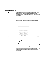
The serial number has two parts: the pre x (two letters and the
rst four numbers), and the sux (the last four numbers). Refer to
Example Serial Number below.
Example Serial Number
The two letters identify the country in which the unit was
manufactured. \US" represents the USA and \MY" represents
Malaysia. The four numbers of the pre x are a code identifying the
date of the last major design change incorporated in your power
sensor. The four digit sux is a sequential number and, coupled with
the pre x, provides a unique identi cation for each unit produced.
Whenever you list the serial number or refer to it in obtaining
information about your power sensor, be sure to use the complete
number, including the full pre x and the sux.
For information concerning a serial number pre x not listed on the
title page, contact your nearest Agilent Technologies Sales and
Service oce.
1-1
08481-90049
8481A/82A/83A
Description
Option 001
(8481A Only)
Accessories Supplied
Caution
1-2
The Power Sensors are used for measuring the average power
supplied by an RF source. In use, the Power Sensor is connected to
the RF source and to a compatible power meter. (Suitable meters
are the 435B, 436A, 437B, 438A, E4416A, E4417A, E4418A/B, or
E4419A/B Power Meter.) The 8481A and 8482A Power Sensors place
a 50 load on the RF source (8483A has a 75 load). The power
meter indicates the power dissipated in this load in W (or mW) and
dBm.
The Power Sensors measure power levels from 030 dBm to +20 dBm
(1 W to 100 mW), at frequencies from 10 MHz to 18 GHz (8481A),
or 100 kHz to 4.2 GHz (8482A), or 100 kHz to 2 GHz (8483A).
The physical con guration of all sensors is the same. However,
because of the di erent frequency ranges covered, there are some
changes in part numbers and component values.
CAL FACTOR data is provided on a label attached to the Power
Sensor's cover. Maximum uncertainties of the CAL FACTOR data
are listed in table 1.
Speci cations for the Power Sensor are provided in table 2.
A precision 7 mm RF connector (APC-7) is substituted for the
type-N connector.
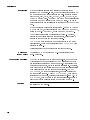
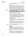
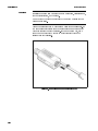
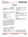
The 8483A is supplied with an adapter (1250-0597, shown in gure
1) for joining the Power Sensor's 75 type N connector to the 50
power reference connector on the power meter. This accessory is a
mechanical adapter only, not an impedance transformer. Therefore,
an impedance mismatch exists that must be taken into consideration
when calibrating the power meter and power sensor. The REF
CAL FACTOR, on the power sensor label, has been adjusted for
the impedance mismatch. This REF CAL FACTOR, when used to
calibrate any power meter, will allow calibration to 1.000 mW. The
CAL FACTOR, from the data on the power sensor label, should be
used for any power measurements in a 75 system at 50 MHz.
Remove mechanical adapter from the Power Sensor before connecting
the sensor to a 75 source.
8481A/82A/83A
08481-90049
Figure 1. Mechanical Adapter (8483A Only)
Recommended
Calibration Interval
Agilent Technologies recommends a one year calibration cycle for the
8481A/82A/83A power sensors.
1-3
08481-90049
8481A/82A/83A
3
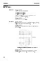
Table 1. Uncertainty of Calibration Factor Data
Frequency
(MHz)
10.0
30.0
100.0
300.0
(GHz)
1.0
2.0
4.0
6.0
8.0
10.0
12.4
14.0
16.0
18.0
(MHz)
0.1
0.3
1.0
Sum of
Uncertainties
6(%)1
8481A
Probable
Uncertainties
6(%)2
Frequency
(MHz)
2.5
2.6
3.1
3.1
1.3
1.4
1.6
1.6
2.7
2.7
2.8
2.8
3.2
3.6
4.4
4.8
5.2
5.8
1.4
1.4
1.5
1.5
1.7
1.9
2.3
2.6
2.9
3.2
3.0
10.0
30.0
100.0
300.0
1000.0
2000.0
4000.0
2.3
2.2
2.2
1.3
1.2
1.2
8482A
(MHz)
0.1
0.3
1.0
3.0
10.0
30.0
100.0
300.0
1000.0
2000.0
Sum of
Uncertainties
6(%)1
8482A (cont.)
Probable
Uncertainties
6(%)2
2.2
2.5
2.6
3.1
3.1
2.7
2.7
2.8
1.2
1.3
1.4
1.6
1.6
1.4
1.4
1.5
2.6
2.5
2.5
2.5
3.0
3.1
3.9
3.9
3.7
3.7
1.5
1.4
1.4
1.4
1.3
1.6
2.0
2.0
2.0
2.0
8483A
1 Includes uncertainty of reference standard and transfer uncertainty. Directly traceable to NIST (National Institute of Standards
Technology).
2 Square root of the sum of the individual uncertainties squared (RSS).
3 Uncertainties are for sensors with type N connectors. Values will be slightly less for sensors with APC-7 connectors.
1-4
8481A/82A/83A
08481-90049
Table 2. Specifications
8481A
Power Range: 030 dBm to +20 dBm (1 W |
Frequency Range: 10 MHz | 18 GHz
Nominal Impedance: 50
Maximum SWR (Re ection Coecient):
Maximum Power: 300 mW Average
Maximum Peak Power: 15W Peak
Maximum Energy/Pulse: 30W 1 s
RF Connector: Type N Male
10 MHz to 30 MHz <1.4 (0.166)
30 MHz to 50 MHz <1.18 (0.083)
50 MHz to 2 GHz <1.10 (0.048)
2 GHz to 12.4 GHz <1.18 to 0.083)
12.4 GHz to 18 GHz <1.28 (0.123)
8482A
Power Range: 030 dBm to +20 dBm (1 W |
Frequency Range: 100 kHz | 4.2 GHz
Nominal Impedance: 50
Maximum SWR (Re ection Coecient):
Maximum Power: 300 mW Average
Maximum Peak Power: 15W Peak
Maximum Energy/Pulse: 30W 1 s
RF Connector: Type N Male
8483A
Power Range: 030 dBm to +20 dBm
Frequency Range: 100 kHz | 2 GHz
Nominal Impedance: 75
Dimensions, Including RF Connector:
Weight: Net, 0.2 kg (8 oz)
Note
100 mW)
100 kHz to 300 kHz <1.60 (0.231)
300 kHz to 1 MHz <1.20 (0.091)
1 MHz to 2 GHz <1.10 (0.048)
2 GHz to 4.2 GHz <1.30 to 0.130)
(1 W | 100 mW)
Maximum SWR (Re ection Coecient):
Maximum Power: 300 mW Average
Maximum Peak Power: 10W Peak
Maximum Energy/Pulse: 30W 1 s
RF Connector: Type N Male (75 )
100 mW)
100 kHz to 600 kHz <1.80 (0.286)
600 kHz to 2 GHz <1.18 (0.083)
30 mm wide, 38 mm high, 105 mm long (1 3/16 in. x 1 1/2 in. x 5 7/8 in.)
When operating in the top 10 dB input power range (e.g. +10 to
+20 dBm), an error due to deviation from square law operation may
occur. This possible error, which applies to the 8481A, 8482A, and
8483A, is expressed as follows:
Worst Case Power Linearity:
+2/-4% (+10 to +20 dBm input range)
+/-3% for EPM Power Meters (+10 to +20 dBm input)
Negligible (-30 to +10 dBm input range)
1-5
08481-90049
8481A/82A/83A
Table 3 lists the test equipment recommended to check, adjust, and
troubleshoot the Power Sensor. If substitute equipment is used, it
must meet or exceed the critical speci cations.
Recommended Test
Equipment
Table 3. Recommended Test Equipment
Instrument Type
Digital Voltmeter
Oscilloscope
Ohmmeter
DC Power Supply
Critical Speci cations
Range: 100 mVdc to 100 Vdc
Input Impedance: 100 m
Resolution: 4-digit
Accuracy: 60.05% 61 digit
Bandwidth: dc to 50 MHz
Sensitivity: Vertical, 0.2 V/div
Horizontal, 1 ms/div
Range: 1 | 100,000
Accuracy: 65%
Range: 5 to 15 Vdc
Suggested Model
Use1
3466A or 34401A
T
1741A, 1980B
or 54622A
A,T
3466A or 34401A
T
6214B or E3610A
T
1 A = Adjustment, T = Troubleshooting
Installation
Initial Inspection
Storage and Shipment
Inspect the shipping container. If the container or packing material is
damaged, it should be kept until the contents of the shipment have
been checked mechanically and electrically. If there is mechanical
damage or if the instrument does not pass the performance tests,
notify the nearest Agilent Technologies oce. Keep the damaged
shipping materials (if any) for inspection by the carrier and an
Agilent Technologies representative.
Environment
The instrument should be stored in a clean, dry environment. The
following limitations apply to both storage and shipment:
Temperature . . . . . . . . . . . . . . . . . 040 to +75C
Relative humidity . . . . . . . . . . . . <95%
Altitude . . . . . . . . . . . . . . . . . . . . . < 7,600 metres (25 000 ft)
Original Packaging
Containers and materials identical to those used in factory packaging
are available through Agilent Technologies' oces. If the instrument
is being returned to Agilent Technologies for servicing, attach a
tag indicating the type of service required, return address, model
number, and serial number. Also, mark the container FRAGILE
1-6
8481A/82A/83A
08481-90049
to assure careful handling. In any correspondence, refer to the
instrument by model number and serial number.
Interconnections
Operation
Refer to the power meter operating and service manual for
interconnecting instructions.
Environment
The operating environment for the Power Sensor should be as
follows:
Temperature . . . . . . . . . . . . . . . . . 0 to +55C
Relative humidity . . . . . . . . . . . . <95%
Altitude . . . . . . . . . . . . . . . . . . . . . < 4,572 metres (15 000 ft)
Operating Precautions
Before the Power Sensor is connected, the following precautions must
be observed.
Warning
BEFORE CONNECTING THE POWER SENSOR TO ANOTHER
INSTRUMENT, ensure that the instrument and power meter are
connected to the protective (earth) ground.
Caution
Note
Exceeding the following energy and power levels may result in
damage to the power meter system.
Maximum Average Power . . . . . . . . . . . . . . . 300 mW
Maximum Peak Power . . . . . . . . . . . . . . . . . . 15W (10W 8483A
Only)
Maximum Energy Per Pulse . . . . . . . . . . . . . 30W 1 s
Do not apply torque to the Power Sensor's body while connecting or
disconnecting the Type N RF connector.
When using the Power Sensor with the 435 series Power Meter make
sure the correct scale is mounted on the Power Meter RANGE
switch. Refer to Section II of the Agilent Technologies 435 series
Power Meter Operating and Service Manual.
Operating Procedures
Instructions for use of the Power Sensor are provided in the power
meter manual. During operation, the precautions described under
\Operating Precautions" must be observed.
1-7
08481-90049
8481A/82A/83A
SWR (Reflection
Coefficient)
Performance Test
The maximum SWR and re ection coecient for each Power Sensor
are listed in table 4. For making these measurements, use equipment
which has measurement uncertainties not exceeding those shown in
the table.
Table 4. SWR and Reflection Coefficient
Frequency
System SWR Uncertainty
Actual
Measurement
Maximum SWR
(Re ection Coecient)
8481A
10 to 30 MHz
30 to 50 MHz
50 MHz to 2 GHz
2 to 12.4 GHz
12.4 to 18 GHz
60.030
60.020
60.020
60.020
60.025
< 1.40 (0.166)
< 1.18 (0.083)
< 1.10 (0.048)
< 1.18 (0.083)
< 1.28 (0.123)
8482A
100 kHz to 300 kHz
300 kHz to 1 MHz
1 MHz to 2 GHz
2 to 4.2 GHz
60.08
60.04
60.02
60.02
< 1.60 (0.231)
< 1.20 (0.091)
< 1.10 (0.048)
< 1.30 (0.130)
8483A
100 kHz to 600 kHz
600 kHz to 2 GHz
FET Balance
Adjustment
Warning
60.08
60.02
< 1.80 (0.286)
< 1.18 (0.083)
The FET balance adjustment should be performed if the wires
connecting J1 to the A2 printed circuit have been moved. If you have
replaced A2 or moved the wires during troubleshooting you will need
to perform this adjustment. You do not need to perform a FET
balance adjustment after an A1 bulkhead assembly replacement if the
wires between J1 and A2 have not been disturbed.
The following procedure exposes high voltage areas within the
power meter. Use extreme care while working around these areas or
personal injury could occur.
Equipment
Oscilloscope . . . . . . . . . . . . . . 54200A
Power Meter . . . . . . . . . . . . . . 435B
Multimeter . . . . . . . . . . . . . . . 3478A
The sampling gate balance is a ected by the relative positions of
the wires in the Power Sensor, which connect to pins G and H of
1-8
8481A/82A/83A
08481-90049
Note
connector J1. One wire is black and white; and the other is brown
and white. Moving the black and white wire will adjust the switching
transient amplitude (spike). Moving the brown and white will change
the o set. Once positioned, care must be used not to displace these
wires. To correctly position these wires, after replacement of the
printed circuit board or if the wires have been moved so as to a ect
the sampling gate balance, perform the following procedure:
1. Set the multimeter controls as follows:
FUNCTION
dc Voltage
RANGE
20 mV, full scale
2. Set oscilloscope controls as follows:
SENSITIVITY
0.2 V/DIV
SWEEP
1 ms/DIV
TRIGGER
INT
DISPLAY
A
3. Set the Power Meter CAL FACTOR to 100%. Set the Power
Meter RANGE to 1 mW (0 dBm).
4. Open the Power Sensor (see \Disassembly Procedure", steps
1 through 3). Zero and calibrate the Power Meter. Leave the
opened Power Sensor connected to the Power Meter POWER
REF output. Heat can a ect the adjustments so handle the
sensor as little as possible.
5. Turn OFF the POWER REF switch on the rear panel of the
Power Meter.
6. Remove the 435B bottom panel. This will expose the circuit side
of the A5 printed circuit board. On A5 you will see a long double
row of soldered terminals numbered 1 to 44.
Opening the 435B meter may void the current calibration and/or
warranty.
7. Connect a probe from pin 40 (the number \902" is printed on the
board next to pin 40) to the multimeter input.
8. Lay the 435B on its left side and remove the right panel. This
will expose the A4 assembly.
9. Connect a 1:1 probe from TP4 to channel A on the oscilloscope.
10. O set. Read the multimeter and adjust the position of the brown
and white wire until the reading is between 03.0 mV and +2.0
mV. Helpful hint: the relative position of the brown and white
wire to C4 will adjust the o set.
11. Switching transients. Read the oscilloscope and adjust the
position of the black and white wire until the switching transients
are less than 0.8V peak to peak. Helpful hint: the relative
position of the black and white wire to the collector of Q1 will
adjust the switching transients.
1-9
08481-90049
8481A/82A/83A
You will nd that positioning the wire for switching transients a ects
the o set. Go back and forth between the two wires, positioning and
repositioning, until both adjustments are within speci cations.
Replaceable Parts
Note
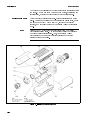
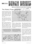
Table 5 is a list of replaceable parts. Figure 2 illustrates the major
parts. To order a part listed in the \Replaceable Parts" table, quote
the part number with Check Digit (CD), indicate the quantity
required, and address the order to the nearest Agilent Technologies
oce.
Within the USA, it is better to order directly from the Agilent
Technologies Parts Center. Ask your nearest Agilent Technologies
oce for additional information. Also, your nearest Agilent
Technologies oce can supply toll free telephone numbers for
ordering parts and supplies.
Figure 2. Illustrated Parts Breakdown
1-10
8481A/82A/83A
08481-90049
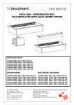
Figure 3. Component and Assembly Locations
1-11
08481-90049
8481A/82A/83A
Table 5. Replacement Parts
Reference
Designation
A1
A1
A1
A1
A1MP1
A1MP1
A1MP2
A1MP3
A1MP4
A1MP4
A1MP5
A1MP6
A1MP7
A1MP8
A1MP9
A1MP10
A1MP11
A1MP12
A1MP13
A1MP13
A1MP13
A1MP13
A1MP14
A2
A2C1
A2C2
A2C3
A2C4
A2C5
A2C6
A2C7
A2C8
A2C9
A2C10
A2MP1
A2MP2
1-12
Part
Number
08481-60004
08481-60005
08482-60003
08483-60003
1250-0918
1250-1466
1250-0016
1250-0916
1250-0917
1250-0816
1460-0977
5020-3296
5020-3297
5040-0306
0470-0013
08481-20015
08481-20016
08481-40006
08481-60009
08481-69009
08482-60004
08483-60006
2190-0831
5061-0982
0180-2515
0160-5947
0160-5947
0180-0594
0160-3094
0160-3879
0160-5947
0160-5947
0180-2515
0180-2545
08481-20008
1251-3363
CD
Qty
3
4
3
4
0
6
0
9
0
8
7
1
2
0
2
2
3
3
8
6
4
7
0
8
8
2
2
9
8
7
2
2
8
4
3
8
1
1
1
1
1
1
1
1
1
1
1
1
1
1
1
1
1
1
1
1
1
1
1
1
1
4
1
1
1
1
1
4
1
1
1
1
Description
BULKHEAD, TYPE N (FOR 8481A ONLY)
BULKHEAD, APC-7 (FOR 8481A OPT 001 ONLY)
BULKHEAD, TYPE N (FOR 8482A ONLY)
BULKHEAD, TYPE N (FOR 8483A ONLY)
NUT-CONN RF
7MM RF CONNECTION ASSY (OPT 001 ONLY)
RING, RF CONN
BODY, RF CONN
CONNECTOR, RF CONTACT
7MM CONTACT (OPT 001 ONLY)
SPRING, COMPR
CENTER CONDUCTOR
SLIDING CONTACT
INSULATOR
SEALANT-THD RED
BULKHEAD
CAP NUT
POLYIRON SLUG (8481A ONLY)
CARTRIDGE ASSY (8481A ONLY)
RESTORED CARTRIDGE ASSY (8481A ONLY)
CARTRIDGE ASSY (8482A ONLY)
CARTRIDGE ASSY (8483A ONLY)
.010 WASHER-FLAT
BD AY PWR SENSOR (8481A, 8482A, 8483A)
CAP-FXD 47uF 6 V TA
CAP-FXD 1000pF
CAP-FXD 1000pF
CAP-FXD 3.3uF 15 V TA
CAP-FXD 0.1uF 100 V
CAP-FXD 0.01uF 100 V
CAP-FXD 1000pF
CAP-FXD 1000pF
CAP-FXD 47uF 6 V TA
CAP-FXD 100uF 4 V TA
END BELL
NUT-AUDIO CONN
Mfr
Code
28480
28480
28480
28480
Manufacturer
Part Number
08481-60004
08481-60005
08482-60003
08483-60003
28480
28480
0180-2515
95275
04222
04222
95275
VJ0805Y102MF
202L1602-335-M4
SR301C104KAAH
SR201C103MAAH
VJ0805Y102MF
28480
28480
202L6301-476-M7-552
202L6301-107-M6-552
08481-20008
1251-3363
8481A/82A/83A
08481-90049
Table 5. Replacement Parts (continued)
Reference
Designation
A2Q1
A2R1
A2U1
A2MP5
A2MP6
A2J1
Part
Number
1854-1179
0698-3260
1813-0060
0590-1040
5040-6938
08481-60024
CD
Qty
0
9
8
1
6
7
1
1
1
1
1
1
MP1
MP2
MP3
MP4
MP6
MP8
MP9
MP10
MP11
MP12
MP13
MP14
MP15
MP16
MP17
MP18
MP19
MP20
5040-6998
5040-6998
08481-20011
08481-20011
1460-1978
08481-00002
08481-00002
0515-0879
0515-0879
0515-0879
0515-0879
0515-0879
0515-0879
0515-0879
0515-0879
0515-0879
0515-0879
0515-0879
9
9
8
8
0
5
5
1
1
1
1
1
1
1
1
1
8
8
2
MP21
0515-0879
8
MP22
0515-0879
8
MP23
3030-0436
4
1
X-N MPSA18 TO-92
RESISTOR 464K +-1% .125W TF TC=0+-100
IC MISC TO-8 PKG MISCELLANEOUS PARTS
NUT-PRESS IN
SPACER
CONNECTOR ASSEMBLY, 12-PIN
CHASSIS PARTS
SHELL, PLASTIC
SHELL, PLASTIC
CHASSIS
CHASSIS
SPRING-CPRSN .088-IN-OD .188-IN-OA-KG
SHIELD
SHIELD
SCREW-SMM 1.6 5 SHHX
SCREW-SMM 1.6 5 SHHX
SCREW-SMM 1.6 5 SHHX
SCREW-SMM 1.6 5 SHHX
SCREW-SMM 1.6 5 SHHX
SCREW-SMM 1.6 5 SHHX
SCREW-SMM 1.6 5 SHHX
SCREW-SMM 1.6 5 SHHX
SCREW-SMM 1.6 5 SHHX
SCREW-SMM 1.6 5 SHHX
SCREW-SMM 1.6 5 SHHX (USED TO MOUNT THE PRINTED
CIRCUIT BOARD)
SCREW-SMM 1.6 5 SHHX (USED TO MOUNT THE PRINTED
CIRCUIT BOARD)
SCREW-SMM 1.6 5 SHHX (USED TO MOUNT THE PRINTED
CIRCUIT BOARD)
SCREW-SKT HD CAP 0-80 .5-IN-LG SST-300
MP24
MP25
MP26
MP27
MP28
5040-6939
5040-6940
1250-0597
08481-80002
08482-80002
7
0
2
3
4
1
1
1
1
1
CLAMP
BLOCK
ADAPTER COAX STR M-N F-N
8481A ID LABEL
8482A ID LABEL
2
1
2
9
4
Description
Mfr
Code
04713
28480
28480
28480
28480
28480
Manufacturer
Part Number
0698-3260
1813-0060
0590-1040
5040-6938
08481-60024
28480
28480
28480
28480
28480
28480
28480
28480
28480
28480
28480
28480
28480
28480
28480
28480
00000
00000
5040-6998
5040-6998
08481-20011
08481-20011
1460-1978
08481-00002
08481-00002
0515-0879
0515-0879
0515-0879
0515-0879
0515-0879
0515-0879
0515-0879
0515-0879
0515-0879
0515-0879
0515-0879
00000
0515-0879
00000
0515-0879
00000
28480
28480
ORDER BY
DESCRIPTION
5040-6939
5040-6940
28480
28480
08481-80002
08482-80002
1-13
08481-90049
8481A/82A/83A
Table 5. Replacement Parts (continued)
Reference
Designation
MP29
MP301
MP32
MP33
Part
Number
08483-80001
08481-80115
08486-80005
7121-2422
CD
Qty
6
7
1
7
1
1
1
1
Description
Mfr
Code
28480
28480
26480
26480
8483A ID LABEL
CAL LABEL (BLANK) - ZEBRA
INFO LABEL (SIDE)
LABEL - CAUTION
Manufacturer
Part Number
08483-80001
08486-80005
7121-2422
1 For MP30, the zebra blank label is to be used with Zebra brand printers. No mylar overlay is necessary. For generating labels using
an older track feed \impact" printer, please order 08486-80006 label blank and 08481-80005 mylar tape, to be installed as an overlay
on top of the 08486-80006, after it is printed.
Table 6. Code List of Manufacturers
Mfr
Code
00000
04213
14140
24546
28480
51959
1-14
Manufacturer Name
ANY SATISFACTORY SUPPLIER
CADDELL-BURNS MFG CO INC
EDISON ELEK DIV MCGRAW-EDISON
CORNING GLASS WORKS BRADFORD)
AGILENT TECHNOLOGIES CORPORATE HQ
VICLAN INC
Address
MINEOLA
MANCHESTER
BRADFORD
PALO ALTO
SAN DIEGO
Zip Code
NY
NH
PA
CA
CA
11501
03130
16701
94304
92138
8481A/82A/83A
08481-90049
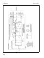
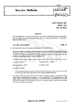
Figure 4. Schematic Diagram
1-15
08481-90049
8481A/82A/83A
Service instructions consist of principles of operation,
troubleshooting, and repairs. Test equipment which meets or exceeds
the critical speci cations in table 3 may be used in place of the
recommended instruments for troubleshooting the Power Sensor.
Service
Note
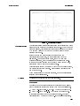
Principles of Operation
1-16
Check your warranty. Opening the Power Sensor will void warranty.
For the following discussion, refer to gure 4 Schematic Diagram and
gure 5 Operational Ampli er. The operational ampli er is made up
of the Power Sensor input ampli er, A2Q1, and the rst ampli er
stage in the power meter.
For additional information on thermocouple sensors, refer to Agilent
Technologies Application Note 64-1C, \Fundamentals of RF and
Microwave Power Measurements".
The A1 Bulkhead Assembly provides a 50 ohm load (8481A and
8482A) or a 75 ohm load (8483A) to the RF signal applied at the
RF INPUT. The rf signal is coupled through a dc blocking capacitor
and absorbed by the thermocouples which generate a dc voltage
proportional to the rf input power. The dc voltage is routed from
the thermocouples to the input ampli er on gold wires to reduce
undesired thermocouple e ects. The gold wires pass through ferrite
beads A2E1 and A2E2 which are located in the black plastic block.
(See gure 2.) The ferrite beads increase the self inductance of the
gold wires causing this portion of the wires to provide the properties
of an rf choke. The result is to minimize rf feedthrough to the A2
Input Ampli er Assembly.
The dc output from the bulkhead assembly is applied to the two eld
e ect transistors (FETs) in A2U1. These transistors function as a
sampling gate or chopper. The sampling rate is controlled by a 220
Hz square wave supplied by the power meter. The amplitude of the
sampling gate output (at pin 3 of A2U1) is a 220 Hz square wave
proportional to the power input. The sampled 220 Hz ac output is
applied to the input ampli er A2Q1 which is the input stage for
an operational ampli er ( gure 5). The ac gain of the operational
ampli er is approximately 700.
A dc feedback voltage from the power meter Auto Zero circuit is
coupled to the input of FET A2U1Q1 to set the zero level. The
voltage is developed across the voltage divider consisting of A2R1
and the series resistance of the thermocouple A1TC1.
When the Power Sensor is used with a Power Meter, the short
to ground at J1-K (Mount Resistor) causes the power meter to
automatically select the proper measurement range of 030 to +20
dBm. With the 435 series Power Meter this short serves no function.
8481A/82A/83A
08481-90049
Figure 5. Operational Amplifier
Troubleshooting
Caution
The troubleshooting information is intended to rst isolate the Power
Sensor or power meter as the defective component. When the Power
Sensor is isolated, troubleshooting information is intended to identify
A1 Bulkhead Assembly or A2 Input Ampli er Assembly as the
defective component.
Before you open the Power Sensor to continue with the
troubleshooting procedures, try the substitution method of
elimination. Use another power meter, known to be in good
operating condition, with the suspected power sensor and cable.
If the same problem occurs with the \known good" power meter,
substitute a \known good" power sensor cable.
Troubleshooting should be performed with the Power Sensor opened,
the printed circuit board exposed. See \Disassembly" close to the
end of this manual.
When a failed assembly has been identi ed, go to \Repair" directly
following \Troubleshooting".
Excessive power will damage the thermocouples.
Power Meter
To ensure the power meter is providing the correct 220 Hz signal,
check the following levels of the square wave with an oscilloscope.
At the white-black wire: 00.05 60.05 Vdc (top of square wave).
At the white-brown wire: 09.0 Vdc (bottom of square wave).
If the levels are correct the Power Sensor is at fault. Continue
troubleshooting A1 Bulkhead Assembly. If the levels are incorrect,
1-17
08481-90049
8481A/82A/83A
the power meter is at fault. Refer to the power meter service manual
for troubleshooting information.
Power Sensor
The most common cause of Power Sensor failure is the application
of power levels beyond the speci ed tolerance. The second most
common cause of failure is applying torque to the body of the Power
Sensor. Either of these common causes will damage the bulkhead
cartridge unit (which holds the thermocouples). If this happens, the
fault will cause a short or an open between the two gold wires.
Caution
Be extremely careful when measuring across the gold wires. They are
delicate and can be damaged easily.
1. Disconnect all cables from the power sensor.
2. Remove the clamp holding the two gold wires.
3. Resistance measured between the two gold wires from the A1
Bulkhead Assembly should be 200 610 ohms (8481A), 245 612.5
ohms (8482A), or 375 617.5 ohms (8483A). If you cannot obtain
the proper resistance (failure is usually indicated by an open
circuit) the A1 Bulkhead Assembly is defective. If the resistance is
correct continue to \A2 Input Ampli er".
A2 Input Amplifier Assembly
It is extremely rare for the A2 Assembly to fail. Eliminate the power
meter, the bulkhead assembly and the connectors before suspecting
the A2 Assembly.
In most cases, the operational ampli er (made up of A2Q1 and the
rst ampli er of the power meter, gure 5) is operating correctly if
the dc voltage on the metal cover of A2Q1 (collector) is 070 630 mV
dc. Refer to the schematic to troubleshoot further.
Repair
Power Sensor repair consists of A1 Bulkhead replacement or repair
and A2 Input Ampli er replacement.
Repair Strategy
You can choose to either replace your A1 Bulkhead
Assembly, or repair it yourself. We recommend replacing the A1
Bulkhead with a new or restored bulkhead over attempting to rebuild
it. A restored Bulkhead is rebuilt and calibrated at the factory. It
comes with a calibration report and new calibration sticker for your
sensor.
If you decide to repair the bulkhead yourself, you should have
an 11760S, 85127A E01 or equivalent automated power sensor
calibration system and, when repairs are nished, the appropriate
SWR test setup. (See table 4 for system speci cations.)
Bulkhead.
1-18
8481A/82A/83A
08481-90049
Note
If you repair power sensors often and have the proper calibration
systems, bulkhead repair can be more economical than replacement.
If the A2 Input Ampli er
Assembly is at fault, replace it. Replacing the A2 Assembly is
usually less costly than than the time it takes to troubleshoot and
replace faulty components. For those who wish to troubleshoot, use
gure 4, \Power Sensor Schematic Diagram".
A2 Input Amplifier Assembly Printed Circuit.
Bulkhead Replacement
Read repair strategy, above. Bulkhead replacement di ers from
repair in that no special tools or skills are required other than those
needed to do the FET balance adjustment.
Procedure
1. Order your new or restored A1 Bulkhead Assembly from table 5,
\Replaceable Parts".
2. Follow the dissassembly and reassembly procedure for bulkhead
removal and replacement located near the end of this manual.
3. Check the FET balance using the procedure that precedes the
parts list. If you did not disturb the wires, it is likely that no
adjustment will be necessary.
4. Place the new calibration sticker on the power sensor cover.
Bulkhead Repair
Read the repair strategy, above. Before beginning repair, inspect the
center conductor and outer conductor with a magnifying glass. If you
have any burrs or scratches visible on the connecting surfaces you
should complete the entire procedure below or replace the bulkhead.
If your connecting surfaces are acceptable, repair your bulkhead by
replacing cartridge (A1MP16) starting with step 9. Do not attempt
repair without the following equipment.
Equipment
Power Sensor Calibration System . .
Type N Connector Gage . . . . . . . . . .
Precision 7mm Connector Gage
(for Option 001) . . . . . . . . . . . . . . . .
SWR Test Set . . . . . . . . . . . . . . . . . . .
11760S or 85127A E01
85054-60024 or equivalent
1250-1875 or 85050-80012
See table 4 for speci cations.
Rebuilding the Bulkhead.
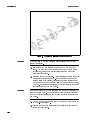
1. Refer to the parts list and gures 6, 7, and 8. Order the internal
type N bulkhead parts A1MP1 through A1MP12. (8482A and
8483A do not use A1MP12 polyiron slug. The precision 7mm
connector A1MP1 comes assembled, so A1MP2 and MP3 are
unnecessary.)
1-19
08481-90049
8481A/82A/83A
2. Set up the necessary equipment for your SWR test. See table 4
in this manual for system speci cations.
3. Remove the bulkhead assembly from the Power Sensor. See the
disassembly procedure near the end of this manual.
4. Using a 5/8 in (16mm) wrench remove the cap nut and
disassemble the bulkhead. Save the cap nut A1MP11, and
polyiron slug A1MP12. Discard the old parts.
5. Build the RF Connector Assembly A1MP1, MP2, and MP3. If
you have an 8481A Option 001, ignore this step.
a. Slip the C-ring into the groove on the RF connector body
(A1MP3).
b. Place the nut face down (knurled end up) on a at surface.
c. While squeezing the C-ring with a long nose pliers, slide the
connector body into the nut until the ring snaps into place.
Figure 6. P/O A1 Bulkhead Assembly
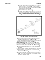
6. Build the Center Pin Assembly A1MP4, 5, 6, 7, 8, and 9.
a. Insert the threaded end of center contact A1MP4, through the
insulator A1MP8.
b. Place a very small amount (use the point of a wooden
toothpick) of red anaerobic sealant A1MP9, on the threads of
A1MP4. Be careful not to get any sealant near the insulator.
1-20
8481A/82A/83A
08481-90049
c. Use your ngers to screw the center contact A1MP4 into the
center conductor A1MP6 until tight. The round insulator
should be squeezed tight enough so that it will not rotate. Do
not scratch or burr the two shafts.
d. Place the spring A1MP5 into A1MP6.
e. Patiently place the sliding contact (snow ake) A1MP7 so that
the snow ake ngers (without being damaged) surround the
spring and press against the inner surface of center conductor
A1MP6. The snow ake should spring back when pressed.
Figure 7. A1 Bulkhead Center Contact Assembly
7. Screw the bulkhead into the center pin assembly as shown in
gure 8. Tighten in place to 50 65 in-lbs (565 N1cm)
8. Use the appropriate gage to verify pin depth. When pin depth is
correct go to next step, \Cartridge Replacement".
If you do not need to replace the inner
and outer conductors of your bulkhead, start here. The procedure
assumes the bulkhead assembly is removed from the Power Sensor.
9. Order one cartridge replacement A1MP13 from the replaceable
parts list.
10. Place the bulkhead on its face, connector side down with the gold
wires pointing up. Using a 5/8 in (16 mm) open end wrench,
remove the cap nut A1MP11.
11. Turn the bulkhead assembly upside down and shake out the old
parts. Watch where the polyiron slug A1MP12 rolls to and keep
it for the new cartridge unit.
Cartridge Replacement.
1-21
08481-90049
8481A/82A/83A
Figure 8. A1 Bulkhead Illustrated Parts Breakdown
Caution
The gold wires on the new cartridge unit are easily damaged and
cannot be repaired.
12. Slip washer A1MP14 inside the bulkhead A1MP10 (for 8481A
only). Now load in the new cartridge unit with the gold wires
pointing out, holding the polyiron slug inside the unit until
everything is in place.
13. Press the top of the bulkhead. A slight springlike action indicates
the cartridge is properly seated. If the cartridge unit does not
spring a little when pressed, carefully remove the cartridge unit
(so you do not damage the gold wires) and use a thinner washer,
A1MP15. If it still does not spring, you should rebuild the center
conductor (step 6) with new parts.
Caution
Damage can occur to both the cartridge and center conductor if they
are not properly mated. If no springlike action (or \give") is present
remove the cartridge assembly and rebuild the center conductor with
new parts.
14. Tighten the cap nut to nger tight then torque the cap nut to to
35 65 in-lbs (395 N1cm).
15. Reassemble the power sensor using the reassembly procedure at
the end of this manual.
1-22
8481A/82A/83A
08481-90049
16. Test for SWR.
17. Check the FET balance using the procedure prior to Replaceable
Parts. (If you were careful not to disturb the wires above the PC
board (A2) this step may not be necessary.)
18. Calibrate the Sensor using your Automated Power Sensor
Calibration System. Place the new sticker on the Power Sensor
cover.
Connector Cleaning
Keeping in mind its ammable nature, a solution of pure isopropyl or
ethyl alcohol can be used to clean connectors.
1-23
08481-90049
8481A/82A/83A
Caution
The RF connector bead deteriorates when contacted by any
chlorinated or aromatic hydrocarbon such as acetone, trichlorethane,
carbon tetrachloride, and benzene.
Do not attempt to clean connectors with anything metallic such as
pins or paper clips.
Clean the connector face by rst using a blast of compressed air. If
the compressed air fails to remove contaminants use a cotton swab
dipped in isopropyl or ethyl alcohol. If the swab is too big, use a
round wooden toothpick wrapped in a lint free cloth dipped in
isopropyl or ethyl alcohol.
Figure 9. Removing the Power Sensor's Cover
1-24
8481A/82A/83A
08481-90049
Disassemble the Power Sensor by performing the following steps:
Disassembly
Procedure
Caution
Note
Disassembly must be performed in sequence described below,
otherwise damage may be caused to the two gold wires between
the bulkhead assembly and the input ampli er assembly. If these
wires are damaged, the A1 Bulkhead Assembly must be repaired or
returned to the factory for repair.
Every Power Sensor has an individually prepared label on the
housing. If more than one power sensor is disassembled at a
time, be sure to mate the correct Power Sensor and housing when
reassembling.
1. Insert the blade of a large screwdriver between the two-piece
plastic shell at the rear of the Power Sensor. Gently pry the
sections apart. (See gure 9.)
2. Proceed to the other side of the connector and again pry the cover
sections apart. Remove the shells and magnetic shields.
3. Position the Power Sensor as shown in gure 8 (top). The small
hole 5 should be on the left side of the RF input connector.
Remove the allen cap screws 1, 2, 10, and 13. Loosen 11 and 12.
Remove the upper chassis from the Power Sensor.
4. Remove the spring clamp cap screw 7 to free the gold leads which
come from the Bulkhead Assembly.
5. Remove cap screws 3, 4, and 5.
6. Slide the Bulkhead Assembly straight out from the chassis.
7. Remove cap screws 8, 9, 11, 12, 14, and 15.
8. Lift the A2 Input Ampli er and J1 connector out of the chassis.
1-25
08481-90049
8481A/82A/83A
Figure 10. Power Sensor Hardware Locations
Reassembly
Procedures
Caution
The gold wires connecting the A1 Bulkhead Assembly and the A2
Input Ampli er Assembly are extremely delicate and may be easily
broken. Be careful when working around them.
1. Set the printed circuit board and connector into place as shown
in gure 10, bottom view.
2. Insert cap screws 8, 9, 11, 12, 14, and 15 but do not tighten.
3. Center the circuit board so there is equal air gap between each
side and the chassis. Tighten 8, 9, 14, and 15.
4. With small hole 5 to the left, carefully insert the gold leads on
A1 bulkhead assembly through the holes in the black plastic
guide on A2 input ampli er.
5. Insert screw 3, 4, and 5. Tighten only screw 5.
1-26
8481A/82A/83A
08481-90049
6. Using tweezers, position the ends of the gold wires over the
electrical pads.
Caution
DO NOT tighten clamp screw 6 excessively or the FET circuit may
be broken.
7. Place and hold plastic clamp 16 over the gold wires. As you
tighten the clamp screw, watch the compression spring. Tighten
the clamp screw 7 only until the spring coils touch. Any further
tightening could damage the FET circuit.
8. Place the upper chassis in position and insert cap screws 1, 2, 10,
and 13.
9. Tighten 1, 2, 3, and 4.
10. Tighten 10, 11, 12, and 13.
11. Place the plastic shells, magnetic shields, and the chassis together
as shown in gure 1. Snap the plastic shells together.
1-27
A
MANUAL CHANGES
This Appendix contains information for adapting this manual to
instruments for which the content does not apply directly.
To adapt this manual to your instrument, refer to Table I-1 and
make the changes listed opposite your instrument serial number.
Table I-1. Manual Changes by Serial Number
Agilent
Instrument
8481A
8482A
8483A
Serial Pre x
or Number
Make Manual
Changes
1550A
1926A
2237A
2349A
2552A
2702A
1551A
1925A
2237A
2349A
2607A
2652A
1602A
1925A
2243A
2329A
2351A
2405A
2623A
2701A
I,H,F,D,B,A
I,H,F,D,B
I,H,F,D
I,H,G,F
I,H
I
I,H,G,D,B,A
I,H,G,D,B
I,H,G,D
I,H,G
I,H
I
I,H,G,E,D,C,B,A
I,H,G,E,D,C,B
I,H,G,E,D,C
I,H,G,E,D
I,H,G,E
I,H,G,
I,H
I
A-1
08481-90049
8481A/82A/83A
CHANGE
INSTRUCTIONS
CHANGE A
CHANGE B
Page 1-13, Table 5:
Change A2 part numbers as follows:
08481-60025 to 08481-60017
08482-60013 to 08482-60005
08483-60007 to 08483-60004
Change J1 to 1251-3228 CONNECTOR, 12 PIN FEMALE
MULTICONTACT 90949 91T-3638.
Page 1-12, Figure 4:
Replace Figure 4 with Figure I-1.
Page 1-14, Table 5:
The part number for MP6 was originally 1460-1224, however,
1460-1978 is the recommended replacement.
Page 1-12, Figure 4:
Replace the area to the right of the A2 Input Ampli er Assembly
with Figure I-1.
MP6.
Figure I-1. J-1 Partial Schematic Diagram (P/O Change 2)
Page 1-14, Table 5:
Change the part number and description of MP30 to:
MP30 08483-00002 CD7 LABEL-CAL INSTRUCTIONS.
MP 30.
A-2
8481A/82A/83A
08481-90049
CHANGE D
CHANGE E
Page 1-12, Figure 4:
In the shaded area to the right of the schematic, connect pin A to the
junction of pins F, M, and J.
Page 1-2:
Replace the sentence which reads:
\The REF CAL FACTOR, on the power sensor label, has been
adjusted for the impedance mismatch."
with:
\The CAL FACTOR at 50 MHz must be multiplied by 0.96 to
determine the REF CAL FACTOR."
Page 1-14, Table 5:
The part number for MP10|MP18 was originally
3030-0422, however, 3030-0954 is the recommended replacement.
Page 1-14, Table 5:
Change the part number and description of MP30 to:
08483-00006 CD1 LABEL-CAL INSTRUCTIONS.
MP10{MP18.
MP 30.
CHANGE F
Page 1-14, Table 5:
Replace MP27 with the following:
7120-3118 CD0 LABEL, ID-LEFT (8481A ONLY)
MP27.
CHANGE G
Page 1-14 Table 5:
Replace MP28 with the following:
7120-4199 CD9 NAMEPLATE .315-IN-WD 2.745-IN-LG AL.
Replace MP29 with the following:
7120-4204 NAMEPLATE .315-IN-WD 2.745-IN-LG AL.
MP28.
MP29.
CHANGE H
CHANGE I
Page 1-11, Figure 3:
Replace gure 3, \Component and Assembly Locations", with gure
I-3.
Page 1, \Instruments Covered by Manual":
This instrument has a two-part serial number. The rst four digits
and the letter comprise the serial number pre x. The last ve digits
form a sequential sux which is unique to each instrument. The
contents of this manual apply directly to instruments having the
serial number pre x listed under \Serial Numbers" on the title page.
A-3
08481-90049
8481A/82A/83A
Figure I-1. Schematic Diagram (P/O Change A)
A-4
8481A/82A/83A
08481-90049
Figure I-3. Component and Assembly Locations
A-5
08481-90049
8481A/82A/83A
By internet, phone, or fax, get assistance with all your test &
measurement needs.
Table A-1. Contacting Agilent
Online Assistance: www.agilent.com/find/assist
United States
Japan
New Zealand
Canada
Latin America
Asia Paci c
Europe
Australia
(tel) 1 800 452 4844
(tel) 1 877 894 4414
(fax) (905) 206 4120
(tel) (81) 426 56 7832 (tel) 0 800 738 378
(fax) (81) 426 56 7840 (fax) 64 4 495 8950
(tel) (305) 269 7500
(fax) (305) 269 7599
(tel) (31 20) 547 2323 (tel) 1 800 629 485
(fax) (31 20) 547 2390 (fax) (61 3) 9210 5947
A-6
(tel) (852) 3197 7777
(fax) (852) 2506 9284