1
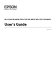
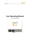
Lotus Service Notes
Section MP
ELECTRICS
SECTION MP
Sub-Section
Page
Vehicle Security Alarm
MP.1
2
Central Door Locking
MP.2
5
Electric Windows
MP.3
6
Switches & Instruments - Driver's Information
MP.4
7
Component Location & Fuse Ratings
MP.5
13
Audio Equipment
MP.6
15
Battery, Battery Cables & Earthing Points
MP.7
16
Wiper Mechanism
MP.8
19
Harness Routing
MP.9
20
Front Lamp Assemblies
MP.10
21
Circuit Diagrams
MP.11
24
Page 1
Lotus Service Notes
Section MP
MP.1 - COBRA VEHICLE SECURITY ALARM
The Lotus Elise/Exige is fitted as standard with a Cobra 8186 immobiliser/alarm which includes the following
features:
•
Elise 111R U.K. approval to Thatcham category 1.
•
'Dynamic coding' of the transmitter keys; Each time the transmitters are used, the operating frequency is
randomly changed to guard against unauthorised code copying.
•
Automatic (passive) engine immobilisation to prevent the engine from being started.
•
Ingress protection using sensing switches on both doors, both front body access panels, and the engine
cover.
•
Personal protection by ‘on demand’ activation of the siren.
•
Selectable cockpit intrusion sensing using a microwave sensor.
•
Self powered siren to maintain protection if the vehicle battery is disconnected.
•
Owner transmitter programming using a Personal Identification Number (PIN).
Transmitter Fobs
Two transmitter fobs are provided with the
car to operate the immobiliser/alarm system.
The two transmitters should be kept separate,
and a replacement obtained immediately after
any loss to ensure that a spare is always available.
Each individual alarm system has a
unique serial number and an owner’s Personal
Identification Number (PIN), both of which are
printed on a code card supplied with the vehicle. In order to allow replacement transmitters
to be ordered, it is essential that these numbers are recorded and kept safely with the
vehicle documents. If the code card is not
available on receipt of the car, enquire with the
dealer immediately.
S/N 99999999
PIN CODE = 9999
Large button
Key tell tale
Small button
COBRA TRANSMITTER & CODE NUMBERS
Engine Immobiliser
In order to provide a measure of automatic vehicle security, independent of any driver initiative, the system
will ‘passively’ immobilise the engine’s cranking and running circuits after the first occurring of the following
approximate time delays:
i)
Four minutes after switching off the ignition.
ii)
Two minutes after a mobilising command (see below).
iii) One minute after switching off the ignition and opening the driver’s door.
The immobilised state is indicated by the security tell tale in the tachometer upper face flashing continuously.
To mobilise the engine, press once, and for a full second, the larger of the two buttons on the transmitter fob.
The security tell tale will be extinguished.
Valet Mode
If leaving the car for servicing or parking, the passive immobilisation feature may be switched off by; switching on the ignition, pressing the transmitter small button, and switching off the ignition. Two beeps will confirm
‘valet’ activation, and the security tell tale will flash continuously, even with the engine running.
At the next arming command, the valet mode will be switched off.
Arming the Alarm
Remove the ignition key, close (and lock) both doors, and check that the engine cover and front body access
panels are secure. The roof may be either closed or open. Press once, and for a full second, the larger of the two
buttons on the transmitter fob (on cars with CDL, this action will automatically lock both doors - see later). This
command will be acknowledged by:
Page 2
Lotus Service Notes
-
Section MP
Two flashes of the hazard warning lamps;
Continuous flashing of the security tell tale.
Check that these indications occur. If not, press the button a second time, as the first press may have only
switched off the passive immobilisation (see above).
Note that if the system is armed when a door or engine cover/front access panel is not fully closed, a
continuous buzz will be heard as warning. If still open after expiry of the arming period, (see below) the alarm will
be armed with that switch group (both doors, or front/rear access lids) excluded from the circuit.
After arming the system, the engine is immediately immobilised, but a period of approximately 45 seconds
must elapse before all functions and sensors become fully active. After this time, the alarm will be triggered by
any of the following actions:
Interruption of the vehicle battery power supply.
Energising the ignition circuit (‘hot wiring’).
Opening a door;
Opening the engine cover or a front access panel.
Movement detected within the cabin.
When triggered, the hazard warning lamps will flash and the electronic wailing siren will sound for a period
of approximately 30 seconds before closing down and resetting, ready for any further triggering input. If a trigger
is continuously present, the alarm will repeat after a short delay, and continue in this sequence for about ten
cycles.
To silence the siren when triggered, press once, and for a full second, the larger button on the transmitter fob.
This will not affect the status of the alarm which will remain armed.
Disarming the Alarm
To disarm the alarm, press once, and for a full second, the larger button on the transmitter fob. This
command will be acknowledged by:
One flash of the hazard warning lamps;
Extinguishing of the security tell tale.
If the alarm had been triggered during the last armed period, the disarm command will be acknowledged by
the hazard lamps flashing 4 times, and the buzzer sounding 4 times. The security tell tale will then flash a code
to indicate the triggering source:
One pulse flashing: door, engine cover/boot lid or body front access panel. On USA cars, check that the
interior lamp is not switched off.
Two pulse flashing: movement detected in cabin by microwave sensor.
Four pulse flashing: tampering with ignition circuit.
Six pulse flashing: interruption of battery supply.
The coding will be deleted when the ignition is next turned on.
Emergency Disarming/Mobilising
If the transmitter fobs are lost or damaged, the alarm system owner’s unique PIN may be used to disarm the
alarm and/or mobilise the engine provided that access is available to the cabin. Follow the transmitter fob
programming instructions (see later) from step 3.
Intrusion Sensing
A microwave sensor is mounted behind the cabin rear bulkhead trim panel, and is able to detect substantial
physical movement within the cockpit, and trigger the alarm. Microwave transmissions are blocked by metal
objects, so it is important not to corrupt the signal by placing such items on the bulkhead ledge.
If desired, the alarm may be armed without the intrusion sensor or battery interruption circuits being active by
arming the system in the usual way with the transmitter larger button, and within 20 seconds, pressing the smaller
button twice.
Page 3
Lotus Service Notes
Section MP
Manual Activation of Horn/Siren
To enhance personal security, with the system in an armed state, the siren may be manually triggered by
pressing the transmitter smaller button. The horn/siren will sound and the turn lamps flash for 15 seconds. To
stop the alarm, press either of the two buttons.
Transmitter Fob Battery Replacement
The transmitter fobs will normally operate within a range of 5 metres from the car, but this may be reduced by
the presence of other radio signals in the vicinity. A small LED tell tale on the transmitter fob will flash whilst the
button is held down to indicate correct operation, but if the lamp flashes irregularly or only once, transmitter
battery replacement is required.
The transmitters are powered by a long life 3V Lithium battery, type CR2032, which with normal use should
last for 3 years. To ensure continuity of operation, it is recommended to renew the batteries every 12 months:
Using a small screwdriver, prise open the case in the areas marked ‘open’.
Remove the old battery and wait for 10 seconds before inserting the new battery with +ve sign uppermost,
and holding the battery only by the periphery.
Align the locating studs, and firmly press the case together.
The transmitter should now operate normally, but may require re-synchronisation with the control unit.
Transmitter Re-synchronisation
If at any time the transmitter does not function, and the battery is known to be good, carry out the following
re-synchronisation procedure:
Stand close to the car and hold down both buttons on the transmitter until the LED on the fob is extinguished
(approx. 10 seconds).
Release both buttons; the fob tell tale should come on constantly.
Press the larger button for one second (the fob tell tale will flash). Synchronisation is complete.
Programming Additional Transmitter Fobs
Two transmitter fobs are provided with the new vehicle. If a transmitter is lost or damaged, a replacement
should be obtained immediately from your dealer, and programmed to the vehicle alarm controller using the
system owner’s unique Personal Identification Number (PIN). Up to four transmitter fobs can be matched with the
alarm system, but all fobs must collectively undergo the single programming operation:
a).
Before programming the transmitters, the PIN should first be verified. If the PIN is incorrect and a working fob
is prepared for reprogramming, all fobs may be disabled. To verify the PIN;
With the car immobilised (tell tale flashing), follow steps (3i) to (3iii) below (i.e. do not prepare any fobs). If
the PIN is correct, the tell tale should be extinguished, and the system mobilised. If not, the PIN is incorrect.
b).
Having verified the PIN as above, proceed as follows:
1.
Press, simultaneously, both buttons on a transmitter fob until the fob tell tale stops flashing (approx. 10
seconds). On release of the buttons, the fob tell tale will light.
Repeat operation (1) for ALL the transmitter fobs required to operate the system.
If the system is immobilised (security tell tale flashing):
i)
Turn the ignition on and off 3 times within 7 seconds; the security tell tale in the tachometer will light for
3 seconds.
ii)
Enter the PIN: Immediately the tell tale goes out, switch ON the ignition and count the number of
security tell tale flashes until equal to the first number of the PIN, then turn the ignition OFF, then back ON
again.
iii) Repeat operation (ii) for the remaining 3 digits of the PIN, remembering to turn the ignition OFF and
back ON after each code number.
Note: If at any time a mistake is made when entering the PIN, turn the ignition OFF for 10 seconds and recommence entering the PIN.
iv). If the PIN is correct, the security tell tale will be out. Carry on with step 4.
With the system mobilised (security tell tale out):
i)
Turn the ignition on and off 3 times within 7 seconds; the security tell tale in the tachometer will light for
3 seconds.
ii)
Enter the PIN: Immediately the tell tale goes out, switch ON the ignition and count the number of
2.
3.
4.
Page 4
Lotus Service Notes
5.
6.
7.
Section MP
security tell tale flashes until equal to the first number of the PIN, then turn the ignition OFF, then back ON
again.
iii) Repeat operation (ii) for the remaining 3 digits of the PIN, remembering to turn the ignition OFF and
back ON after each code number.
Note: If at any time a mistake is made when entering the PIN, turn the ignition OFF for 10 seconds and recommence entering the PIN.
After finishing step (4) with the ignition on, within 7 seconds, press once the large button of each transmitter
fob.
Turn off the ignition.
Test operation of each transmitter fob.
Location of Components
The alarm system components are located as follows:
Electronic Controller: Mounted on top of the scuttle beam at passenger's extreme end. Accessible after
removal of fascia top.
Siren Unit: Mounted on front of radiator duct LH extension, beneath LHF turn lamp. Accessible only after
removal of front clamshell.
Immobiliser Module: Mounted on left hand end of cabin rear bulkhead. Accessible after removal of rear
bulkhead trim panel.
Microwave Sensor: Mounted centrally on cabin rear bulkhead, beneath trim panel.
Engine Lid Sensor: Mounted on luggage compartment bulkhead, alongside latch.
Front Access Panel Sensors: Mounted on brackets fixed to topshell at outboard edge of aperture.
Front access cover sensor
Electronic controller
Microwave sensor
Engine lid sensor
Siren unit
Door switch
Immobiliser module
m240a
Identification of alarm controller
Note that earlier Elise variants have used versions of the alarm controller with and without CDL functionality.
For Elise 111R and Exige models with CDL, the controller should be printed with the identification 8185 4C8170AIB.
Page 5
Lotus Service Notes
Section MP
MP.2 - CENTRAL DOOR LOCKING (if fitted)
The central door locking (CDL) operates on the driver’s and passenger’s doors in conjunction with the
security alarm system, which includes CDL circuitry in the Cobra 8186 alarm controller.
To lock the car, remove the ignition key, close both doors and check that the engine cover and front body
access panels are secure. Arm the security alarm in the usual way by pressing once, for a full second, the larger
of the two buttons on the transmitter key. This action will both arm the alarm and electrically lock the driver’s and
passenger’s doors.
If it is desired to lock the doors from inside the vehicle, for example to deter highjack attempts, a CDL rocker
switch is provided on the front of the gear lever shroud which should be pressed to the right to lock both doors with
or without the ignition switched on. Alternatively, the doors can be locked individually by depressing the button at
the rear end of each door sill. Note that whichever locking method is used, the doors will be ‘deadlocked’ such that
the interior door release handles are inoperative.
To unlock the doors, press once, for a full second, the larger button on the transmitter key. The alarm will
be disarmed and both doors unlocked. Alternatively, from inside the car, press to the left the rocker switch on the
gear lever shroud to unlock both doors, or raise the sill button on each door. Note that in the event of a vehicle
collision which causes the safety inertia switch to be tripped, the doors will automatically be unlocked.
Notes:
In the event of a flat vehicle battery, the
central door locking will not operate. The
doors can be unlocked from outside only
after:
Elise; opening the engine cover and restoring power to the battery by substitution, re-charging or ‘jumping’ to a second
battery.
Exige; removing the front body passenger side access panel and providing a 12
volt supply to the auxiliary power point.
EXIGE AUXILIARY
BATTERY POSTS
ohs142
-
-
To lock the car with a flat or disconnected battery, use the mechanical key in each exterior door button to
disconnect each release button from the latch. This technique does not 'deadlock' the interior release
handles, but does allow continued key access to the car until restoration of battery power.
To deadlock the car with a flat vehicle battery, or without the use of the transmitter or mechanical key, close
and lock one door using the sill button, and for the second door, hold the exterior release button pressed in
and depress the sill button before closing the door. Access is now available only on restoration of electrical
power.
Door Locking Actuator
A CDL actuator is screw fixed to the door shell below the latch mechanism, and uses a link rod which
passes through the innermost hole on the latch lever, before continuing upwards to the door sill button. For
replacement details, refer to sub-section BP.17.
Modules, Fuses & Relays
A CDL module is mounted on the top of
the scuttle beam at the extreme end on the
driver's side, accessible after removal of the fascia top trimmed panel and face level vent
trunking (if fitted). A battery feed for the CDL
system is provided from fuse A22 (7.5A).
m251
Page 6
CDL module
Lotus Service Notes
Section MP
MP.4 - SWITCHES & INSTRUMENTS - DRIVER'S INFORMATION
Ignition Switch/Steering Lock
The switch/lock is located on the right hand side of the steering column.
IInsert the key into the slot, and turn clockwise to position ‘I’ to unlock the steering column. If the key is
reluctant to turn, wriggle the steering wheel to ease the load on the steering lock.
II - Turn to position ‘II’ to switch on the ignition and operate auxiliary equipment.
III - Turn further clockwise to ‘III’ against spring pressure to operate the starter motor. As soon as the engine
starts, allow the key to return to position ‘II’. For the correct starting procedure, see the later chapter
‘Starting Procedure & Running In’. To stop the engine, turn the key back to ‘I’.
Passive Immobilisation: If the ignition has been switched off for longer than four minutes, or longer than one
minute after switching off the ignition and opening the driver’s door, the passive immobilisation security
feature will operate and disable the ignition and starter circuits. This condition is indicated by the security
tell tale flashing continuously. To mobilise the engine, press once, and for a full second, the larger of the two
buttons on the transmitter fob. The security tell tale will be extinguished.
B - To remove the key, turn fully counterclockwise to ‘B’ and withdraw. The steering column lock will be activated when the key is withdrawn but may not engage until the steering is turned and the mechanism is
aligned.
DO NOT leave the ignition switched on for long periods without the engine running, since although the engine
ignition system itself draws no current when the engine is stopped, a battery drain will occur through other circuits
even when auxiliary equipment is not being used.
For security reasons, and to guard against battery drain, always remove the key when leaving the car.
WARNING:
Do not push or tow the car unless the key is first used to unlock the column and is then left in the
lock.
Never withdraw the key until the vehicle is stationary.
To reduce the risk of theft, or danger to a child remaining in the vehicle, always remove the key
when leaving a parked car.
Tell Tale Lamps
A block of tell tale lamps is incorporated
into the instrument cluster to indicate the operational status of various systems.
Bulb Check
In order to check that the warning systems are operative, all the tell tale lamps (except the ‘security’ tell tale; see Vehicle Security Alarm) should light for about six seconds
following ignition switch on. If any lamp should
fail to light, it is possible that the bulb or warning circuit may be faulty.
a
b
c
d
e
g
a
h
b
i
c
j
d
k
e
g
h
i
j
k
Euro
f
USA
f
S.I.R. (Airbag) Tell Tale (USA h)
The Supplementary Inflatable Restraint system has a self-diagnostic facility which lights the red tell tale if a
fault is detected. As a bulb and circuit check, the tell tale will light briefly when the ignition is switched on, and
then go out. If the lamp lights at any other time, a fault in the S.I.R. system is indicated, which should be rectified
without delay.
Turn Tell Tale (a)
When the left hand or right hand turn indicators are operating, this green tell tale flashes in unison. The
flasher relay may also be heard to operate. If the tell tale fails to light, or flashes at an unusual or irregular rate,
check the operation of the turn indicator lamps immediately.
Page 7
Lotus Service Notes
Section MP
Seat Belt Tell Tale (b)
`The red seat belt tell tale is provided as a reminder that both driver and passenger should always wear the
seat belts, no matter how short the journey. The lamp will light for about 8 seconds following ignition switch on,
before being extinguished. On USA market cars, the lamp will flash until the driver's seat belt is fastened,
accompanied for the first eight seconds by an audible chime.
Brakes Tell Tale (c)
This tell tale will glow red with the ignition switched on whenever the parking brake is applied. Driving the car
with the brake not fully released will cause overheat damage to the rear brakes. Each time the parking brake is
released, check that the tell tale is extinguished.
With the parking brake released, if the tell tale should light at any time after the check period, stop the car
immediately, as the circuit has detected a dangerously low level of brake fluid in the master cylinder reservoir,
possibly caused by a hydraulic leak in one of the separate front or rear brake circuits. There is a danger that air
may enter the hydraulic system and cause spongy operation and extended pedal travel. The divided brake circuit
should ensure that emergency braking remains, but the car should not be driven until the fault has been identified
and rectified.
Oil Pressure Tell Tale (d)
This red tell tale warns of low engine oil pressure. The lamp will be lit whenever the ignition is on and the
engine is stopped, but should extinguish as soon as the engine is started. If the lamp fails to go out after engine
start up, or comes on when the engine is running, stop the engine immediately and do not restart until the cause
has been investigated and rectified. Continuing to run the engine with little or no oil pressure could cause major
internal damage, possibly resulting in seizure.
Low Fuel Level Tell Tale (e)
When only a single segment of the fuel gauge bar graph remains, representing approximately 5 litres, this
amber tell tale will flash. Refuel at the next opportunity.
ABS Tell Tale (f)
This amber tell tale should light for about four seconds following ignition switch on, and then go out. If the
lamp remains lit, or comes on whilst driving, a fault in the ABS is indicated. The base brake system will continue
to operate normally, but without ABS regulation. The car can be driven but should be checked and repaired at the
earliest opportunity.
Main Beam Tell Tale (g)
This lamp glows blue whenever the headlamp main beams are operating.
Rear Fog Lamps Tell Tale (Euro h)
This lamp glows amber whenever the rear fog lamps are operating (see ‘Rear Fog Lamp Switch’).
Battery Charging Tell Tale (i)
This red tell tale will light whenever the ignition is on and the engine is stopped. If it lights any time that the
engine is running, the battery is not being charged, which may be due to a broken alternator drive belt, or an
electrical fault. Urgent attention is required, but as the engine coolant pump is independently driven, the car need
not be stranded, subject to battery condition and local circumstances.
Low Tyre Pressure Tell Tale (If applicable) (j)
On cars equipped with this feature, the tell tale lamp will light up amber if a wheel speed discrepency is
detected, indicative of a deflating tyre. Stop the car as soon as safely possible and check all four tyres.
Malfunction Indicator Lamp (k)
The engine Malfunction Indicator Lamp (MIL) is provided to warn the driver that the engine management
system has detected a fault which may result in increased noxious emissions from the exhaust. In order to
minimise emissions and potential engine damage, various operational limitations may automatically be applied.
i)
If the MIL lights continuously whilst driving, immediately reduce speed and adopt a moderate driving style.
Seek dealer advice without delay and avoid all unnecessary journeys.
ii)
If the MIL flashes, an engine misfire has been detected which is likely to cause overheat damage to the
Page 8
Lotus Service Notes
-
-
Section MP
catalytic converter. Slow down immediately and be prepared to stop.
If the MIL then stops flashing, and is lit continuously, proceed with caution and seek dealer advice.
If the MIL continues to flash, stop the vehicle as soon as it is safe to do so, and switch off the engine. Seek
dealer advice.
Note:
Continuing to drive the car with a flashing MIL may cause overheat damage to the catalytic converter and
increased noxious emissions.
In order to comply with emissions regulations, data regarding activation of the MIL is recorded in the engine
electronic controller, and may be downloaded by Lotus dealers.
Security/RPM Tell Tale
The security tell tale is located at the top of the tachometer display, and indicates the status of the immobiliser and alarm.
Tell tale out; engine is mobilised, and the alarm is off.
Tell take flashing; engine is immobilised, or alarm is armed and engine immobilised.
For full details of the vehicle security system, refer to the earlier section ‘Vehicle Security’. Note that the tell
tale also functions as a high engine speed (rpm) warning - see ‘Tachometer’.
Instruments
Speedometer
This instrument displays road speed in either MPH (with a secondary scale in km/h), or km/h according to
market.
Tachometer
The tachometer indicates engine speed in revolutions per minute. A safeguard in the engine management
system limits the maximum continuous engine speed to 8000 rpm once normal running temperature has been
attained. Very short bursts up to 8500 rpm are allowed during maximum acceleration through the lower gears. A
6000 rpm limit is imposed on a cold engine in order to reduce possible damage from unsympathetic use. The use
of wide throttle openings and/or high rpm before normal running temperature has been reached will result in
premature wear and should be avoided. Do not run the engine continuously at its maximum speed, or allow
overspeeding to occur on the overrun by changing down through the gears too early, as this imposes very high
loads on engine components, resulting in premature wear and possible failure.
A red tell tale lamp in the top of the tachometer face lights at high rpm (dependent on gear engaged) to warn
that maximum engine speed is being approached. When exploiting full acceleration, gearchange upshifts should
be made immediately the tell tale lights. Note that this lamp also functions as a security system tell tale (see
‘Vehicle Security’).
Recalibration of the tachometer needle position will occur during a three second period following ignition
switch on, but if a needle becomes 'stranded' outside of the re-calibration range, the following procedure should be
followed:
Open driver's door;
Press and hold trip reset button on column shroud;
Turn on ignition.
Security/RPM tell tale
Tachometer
INSTRUMENT POD
Speedometer
ohs127
Page 9
Lotus Service Notes
Section MP
LCD Panel
A liquid crystal display (LCD) panel is provided below the instruments in order to display fuel level, coolant
temperature, total mileage and trip functions. The panel is blank until the ignition is switched on.
Fuel Contents Display
An indication of the level fuel in the tank
is displayed in the form of a bar graph at the
right hand top of the LCD panel in the instrument cluster. When completely full (approximately 43.5 litres (9.6 U.K. gal), the display
will show six black segments. As the fuel level
falls, a white band will extend from the right to
represent the empty portion.
When only a single segment remains,
representing approximately 5 litres, the amber
low fuel tell tale will flash. Refuel at the next
opportunity.
Trip distance
Proportion of fuel remaining
Odometer
LCD DISPLAY PANEL
Coolant temperature
m253
Coolant Temperature Display
The engine coolant temperature will be displayed at the bottom right hand corner of the panel as soon as the
temperature reaches 72°C. The running temperature will fluctuate a certain amount as the operating conditions
change, and during periods of idling or in heavy traffic, the temperature may rise to over 100°C, with the cooling
fans switching on at half speed at approximately 98°C and at full speed at approximately 103°C. The display will
flash at temperatures over 110°C in order to prompt closer monitoring of high temperatures, but as the pressurised
cooling system has a boiling point of over 120°C, only if the temperature approaches this level need there be any
cause for concern. If this should occur, allow the engine to idle for a few minutes whilst monitoring the temperature, and if it continues to rise, switch off and seek qualified assistance.
After a heavy snowfall, ensure that the radiator cooling outlet grilles in the front body are cleared of snow
before driving the car, or overheating may occur.
Odometer
An odometer (total distance recorder) reading is displayed at the bottom left hand corner of the panel, and is
calibrated in the same units (miles or kilometres) as is the speedometer.
Trip Recorder
A trip recorder is provided at the top left hand corner of the panel, calibrated in the same units as is the
speedometer.
In order to zero the trip display, switch on the ignition, and press for a moment (less than 1 second), the
small button on the steering column shroud between the ignition switch and steering wheel. This dual function
button also controls the panel illumination - see ‘Instrument & Switch Illumination’.
Fascia Switches
Lighting functions are controlled by a vertical row of three push button switches mounted in the fascia
outboard of the steering column. Each switch is pressed once to switch on, and pressed a second time to switch
off. A symbol is positioned alongside each switch to indicate its function, and is backlit orange when the lights are
switched on.
Sidelamp Switch
The topmost switch functions with or without ignition, and switches on the sidelamps. A tell tale in the
switch button lights up green to indicate when the circuit is active. Note that the headlamps must be off before the
sidelamps can be switched off.
Headlamp Switch
The centre switch functions with or without ignition, and switches on the headlamps together with the
sidelamps if not already selected by the sidelamps switch. A tell tale in the switch button lights up green to
indicate when the circuit is active. The steering column lever switch (see later) is used to select main beam or dip.
Page 10
Lotus Service Notes
Section MP
Pressing the switch a second time will switch off the headlamps, but leave on the sidelamps.
'Lights On’ Buzzer
A ‘lights on’ reminder buzzer will sound if the lights are on when the ignition is switched off and the driver’s
door is opened.
Sidelamps
Headlamps
Rear Fog
ohs109a
Rear Fog Lamp Switch
The lowermost switch controls the two rear fog lamps (where fitted), and may be selected only after first
switching on the ignition, and then the headlamps. A tell tale in the switch button lights up amber to indicate when
the circuit is active.
Note that the switch will default 'off' whenever the headlamps or ignition are switched off, requiring re-selection if lamp acivation is again desired.
In some territories, rear fog lamps may be used legally only in conditions of ‘seriously reduced visibility’. Be
aware that indiscriminate or forgetful use of the rear fog lamps can cause distraction and discomfort to following
traffic.
Hazard Warning Lamps Switch
The hazard warning switch is located immediately ahead of the gear lever in the centre shroud, and has an
icon in the switch button which is back lit when the ignition is switched on. The switch is operative at all times,
and when pressed flashes all the turn indicator lamps, and the switch tell tale, in unison. Press a second time to
switch off.
This facility should be used when the vehicle has to be stopped on the highway in abnormal circumstances,
where a warning to other traffic would be judicious. Use of the hazard warning lamps may be subject to local traffic
laws, with which drivers should familiarise themselves.
Instrument Illumination
A small button is provided on the steering column shroud, between the ignition switch and steering wheel, by
which the brightness of the instrument illumination may be adjusted. To cycle through the range of brightness,
press and hold the button, and release at the desired setting.
This dual function button also resets the trip distance recorder - see ‘Trip Recorder’.
Auxiliary Power Socket
An auxiliary power socket is fitted in the
centre trim shroud below the oddments pocket
on the rear bulkhead. The socket is operative
at all times, and is provided with a protective
hinged flap and an illumination ring which is
backlit red when the lights are switched on.
The format of the socket allows a standard cigarette lighter element to be used, or other
electrical accessories requiring this type of fitting. Maximum current draw should not exceed 15 amps.
AUXILIARY
POWER
SOCKET
ohs144
Page 11
Lotus Service Notes
Section MP
WARNING: Do not leave small children unattended in the car since careless interference with the power
socket could be dangerous.
Headlamp Dipswitch/Flasher/Turn Indicators
The steering column left hand lever switch controls the headlamps main beam/dip, headlamp flash and turn
indicators.
Headlamp Dipswitch: To switch on the
Right
headlamps, press the headlamp switch in the
turn
fascia outboard of the steering column. The
left hand lever switch is then used to select
main or dip beam. Main beam is obtained with
the lever furthest forward, away from the
steering wheel, and dip beam with the lever
moved back towards the wheel. The main beam
Left
Main beam
tell tale lamp in the instrument panel lights
turn
when main beam is operating.
Dip beam
Note: i) When main beam is selected, the dip
Flash
beam lamps remain lit. ii) On cars equipped
with optional auxiliary main beam lamps
mounted in the radiator air intake, the auxiliary
lamps operate in conjunction with the body
mounted headlamp main beams.
Headlamp Flasher: The headlamp flasher is operative at all times. If the lever is pulled towards the steering
wheel against spring pressure, the headlamp main beams will light.
Turn Indicators: The turn indicators operate only with the ignition switched on. Move the lever down to indicate
a left hand turn, and up for a right hand turn. The switch will be cancelled when the steering wheel is returned to
the straight ahead position.
For convenience, when signalling a lane change, lightly pressing the switch up or down will allow its return
under spring action.
ohs32
Windscreen Wiper/Washer
The steering column right hand lever switch controls the windscreen wiper and washer, and is operative only
with the ignition switched on. Never use the wiper on a dry screen.
Windscreen Wiper: The wiper is controlled by
Wiper
the up/down position of the lever switch, which
operates as follows:
Moved fully down, the wiper is switched
off.
Move up to the first position for
intermittent wipe. The wiper will make
one sweep about every five seconds.
Select the next position for normal wiper
operation.
Move fully upwards for quick wipe, to be
used only in heavy rain.
Washer
ohs33
Windscreen Washer: Two windscreen washer jets are provided, one each side of the wiper spindle. Pulling the
control lever towards the steering wheel will operate both the washer pump and the wiper. When the switch is
released, the wiper will continue for a further four sweeps.
Horn
The windtone horn, which functions at all times, is operated by a central button in the steering wheel boss.
Interior Lamp
An interior lamp is mounted centrally in the rear bulkhead trim panel and is equipped with a three position
rocking lens:
Page 12
Lotus Service Notes
-
Section MP
Lens rocked upwards; lamp is switched off. NOTE: On USA cars, arming the alarm with the interior
lamp switched off may exclude the doors from activating the alarm.
Lens central; lamp is switched on, with or without ignition.
Lens rocked downwards; a courtesy mode applies, where the lamp is switched on whenever a door is
opened, and goes out when the doors are closed. In addition, the alarm disarm command will also light the
interior lamp for a period of 30 seconds, or until the ignition is switched on.
-
Inertia Switch
The safety inertia switch is designed to
operate on impact, typified by vehicle collision,
to switch off the fuel pump, and thus minimise
any fire hazard. The inertia switch is mounted
at the left hand rear corner of the engine bay,
and is reset by pressing the rubber diaphragm
button on the top of the unit.
INERTIA
SWITCH
ohs137
MP.5 - COMPONENT LOCATION & FUSE RATINGS
Main Fusebox
The main fusebox is located in the front services compartment, on the passenger side, and is protected by
a plastic cover. For access, remove the passenger side front body access panel, and unclip the fusebox lid.
Twenty two slots are provided for ‘Littel’ type fuses which are numbered, and coloured according to their amperage
rating, and may be pulled out from their slots using the fuse extractor tool provided on the fusebox lid.
m254
As viewed from in front of Elise:
Fuse 1
Fuse 11
Fuse 12
Fuse 22
m255
MAIN FUSEBOX
Slot
1
2
Rate
20A
2A
3
4
5
20A
20A
7.5A
6
7
8
9
10
11
12
7.5A
10A
7.5A
10A
7.5A
10A
10A
Circuit
Aux. power socket
non USA: Alarm siren
USA: Reverse lamps
Driver window
Passenger window
Stoplamps
non USA: Reverse lamps
Turn indicators
Ignition services
Battery services
Hazard lamps
Horn
Alarm power, interior lamp
ABS
Slot
13
14
Rate
3A
20A
15
16
7.5A
10A
17
18
19
10A
10A
20A
20
21
22
15A
15A
7.5A
Circuit
ECU ignition
Rad. fans;
1&2 slow, 1 fast
Radio, switch pack module
Sidelamps
non USA: Rear fog
Dip beam LH
Dip beam RH
A.C. comp. relay,
rad fan 2 fast
Main beam LH
Main beam RH
CDL
Page 13
Lotus Service Notes
Engine Compartment
Fuses and relays associated with the
engine management system are contained in
two 4-position fuse holders located at the front
of the engine bay on the cabin bulkhead, adjacent to the engine ECM. To access the fuses,
unclip rear edge of the cover.
Fuse no.
R1
R2
R3
R4
R5
R6
R7
R8
Rating
20A
3A
5A
5A
5A
7.5A
10A
5A
Section MP
ENGINE BAY FUSES
4
3
2
1
Circuit
Fuel pump
Immobiliser
Alternator sense
ECU battery feed
O2 heaters
VSV's VVT, VVL, IAC
Injectors, ignition coils
Re-circ. pump
ohs136
Front
Interior Fuses & Relays
The wash/wipe module, turn/hazard flasher
relay, horn relay and a relay for inertia switch
activation of the central door locking, are
mounted on the scuttle beam above the passenger footwell, with four fuses secured to the
harness in that area.
Fuse no.
C1
C2
C3
C4
Rating
20A
15A
7.5A
10A
8
7
6
5
Circuit
Interior fan
Wiper motor
Audio key-in
A.C. compressor
Fusebox ‘C’
!
Viewed
from
beneath
m248a
A 60A Maxi fuse protecting the ABS circuit is located beneath the passenger side fascia top, adjacent to the
positive post.
A multi-function relay unit containing the engine control relay, fuel pump relay and starter relay is mounted in
the engine bay near the ECU. A similar relay unit is mounted in the front services compartment alongside the
fusebox, and operates the a.c. compressor and radiator fans. Important Note: Although the two modules are
identical in appearance, their function is different and they must not be transposed. The a.c. relay module
A117M0038F has a brown label marked YWB100800; The engine relay module A111E6024F has a white label
marked YWB100970.
For the location of the vehicle alarm system components, see sub-section MP.1.
Fuse colours:
2A - Black
3A - Violet
15A - Light Blue 20A - Yellow
Page 14
4A - Pink
25A - Clear
5A - Orange
7.5A - Brown
10A - Red
Lotus Service Notes
Section MP
Component Location - Illustration to be revised
CDL module
Horn mounted
on crash structure
Engine bay fuseboxes
ECU
mounting
plate
Fusebox
Inertia
switch
Radiator fan/a.c.
control module
ABS
fuse
Switch
controller
Fuse
block
Rear fog module
CDL trip relay
Flasher unit
Wiper delay
pl1703mt
MP.6 - AUDIO EQUIPMENT
Front speaker
The Elise may be specified with various
audio equipment options. All cars are fitted with
a main wiring harness which includes: an ISO
16-way connector located behind the standard
ISO size audio aperture in the dash panel;
speaker wiring terminating behind the cabin LH
rear corner trim panel; and an analogue di-pole
aerial routed inside the front body. On cars
factory built with a digital audio set, this aerial
is supplemented by a digital di-pole aerial routed
in a similar manner.
Speaker
grille
Speakers
'Two speaker' cars are fitted with a
speaker in each cabin rear corner in a sound
deadening full width rear bulkhead trim panel.
An upgraded audio option uses the same rear
speakers, in conjunction with a pair of front
speakers, mounted one in each dash end panel.
USA cars have the front speakers mounted in
the fascia top panel.
m243
Page 15
Lotus Service Notes
Section MP
Speaker specifications are as follows:
Rear: Blaupunkt GTX 542 2-way co-axial; 90W max; 30W RMS; 4 ohms impedance.
Front: Blaupunkt TSX 402 2-way co-axial; 105W max; 35W RMS; 4 ohms impedance.
To remove the rear bulkhead trim panel, remove the four screws securing the top edge of the panel to the
bulkhead plinth, and ease the panel from behind the seat belt mounting frame at each side.
MP.7 - BATTERY, BATTERY CABLES & EARTHING POINTS
Battery
WARNING: POISON/DANGER - CAUSES SEVERE BURNS - KEEP OUT OF REACH OF CHILDREN.
Contains sulphuric acid - avoid contact with skin, eyes or clothing. If in contact with skin or eyes; flush
with copious amounts of water. Remove contaminated clothing. Seek immediate medical attention. If
ingested; seek immediate medical attention . Do not induce vomiting or give fluids to drink.
Batteries produce explosive gases. Keep sparks, flames and cigarettes away. Ventilate when charging
or using in enclosed space. Always shield eyes when working near batteries.
Battery Access
The 45 Ahr Yuasa type 063/3 battery is located at the left hand front of the rear luggage compartment. No
routine inspection or topping up of the electrolyte is required, but at intervals specified in the Maintenance Schedule, the battery terminals should be checked for security and condition, and protected with petroleum jelly.
To remove the battery, unhook the plastic cover, disconnect both battery cables (see below), and pull off the
breather pipe (if applicable). Release the single screw securing the clamp bracket at the rear base of the battery,
and manoeuvre the battery from the base retaining shoes at the front and right hand side. When lifting out the
battery, be aware of the considerable weight, and take all appropriate precautions to safeguard personal health.
Refit the battery, with its terminals inboard, by reversing the above procedure. Remember to push on the
breather pipe (if applicable), and reconnect the battery cables as detailed below.
Battery
clamp
ohs145
Disconnecting the Battery
If the battery is to be disconnected, the following precautions should be taken:
i)
Wait for at least ten seconds after switching off the ignition to allow the engine management system to
adjust the setting of some components ready for re-starting.
ii)
If the car is fitted with the upgraded security alarm, immediately before disconnection, mobilise the engine
using the transmitter button with ignition off, and disconnect the battery within 25 seconds. If disconnected
after this time, or when immobilisation is in effect, the alarm will be triggered.
iii) Ensure that all electrical loads (e.g. lights) are switched off.
iv)
Disconnect the negative (earth; black; ‘-’) battery cable first, and re-connect last. If the battery positive
terminal is inadvertently earthed (e.g. when using a spanner) whilst the negative terminal is still connected,
the resultant short circuit with heavy sparking and current flow could cause serious burns.
v)
If the vehicle is fitted with security coded audio equipment, check that the code is available for entering after
battery reconnection.
Page 16
Lotus Service Notes
Section MP
Battery Reconnection
i)
Check again that all electrical loads are switched off.
ii)
Connect the positive battery cable first, followed by the negative (earth) cable.
iii) Be aware that the vehicle security alarm may be triggered by the action of battery re-connection. Have the
alarm transmitter key ready to disarm the alarm (see ‘Vehicle Security Alarm’).
iv)
After reconnection, a change in the engine performance characteristics may be noted for a period whilst the
computer controlled engine management system ‘re-learns’ some of its settings.
v)
If necessary, enter the security code into audio equipment.
Battery Charging
Under conditions of normal daily use, it should not be necessary to use external battery charging equipment.
In a low usage regime, however, it is important to maintain the charge state of the battery using a trickle charger,
or an automatic battery management charger such as that available through Lotus After Sales. Such devices,
when connected to a vehicle battery, continuously monitor battery charge state and switch on and off automatically in order to maintain the battery in a fully charged state without danger of damage through overcharging.
If the battery becomes discharged to the extent that the vehicle cannot be started, the recommended course
of action is to fit a substitute battery whilst the original battery is trickle charged. If, in an emergency, the vehicle
has to be ‘jump’ started, the subsequent conditions of vehicle use may not allow for sufficient alternator charging
of the battery to achieve a fully charged state. The battery should be trickle charged until 12.8 volts is recorded,
which process may take 24 hours or longer. Putting the battery into service at a lower state of charge will reduce
the time period for which the vehicle can be parked. A battery left in a fully discharged state for a prolonged period,
may not be recoverable to its original condition.
Unless using an automatic battery management charger, the battery should be removed from the car for
recharging, to a well ventilated area to avoid a build up of fumes in the luggage compartment and to prevent
damage to the car's electrical system. Observe the safety precautions listed above when removing the battery
and take care to avoid sharp knocks or shocks, keeping the battery as upright as possible. Beware of the
considerable weight of a battery, and take necessary precautions against personal injury.
Check that the electrolyte level is between the upper and lower markers on the battery case, and if necessary add distilled water. The recommended bench charge rate is 4 amps. When the battery is fully charged (12.8
volts), allow the battery to stand for an hour before refitting into the battery well and reconnecting the leads - see
above.
Quiescent Drain
With a fully charged battery, the current drain with all electrical equipment switched off (no radio fitted)
should be as follows;
Immobiliser active
15 mA
Alarm set
20 mA
If current drain is found to be significantly in excess of these figures, the cause must be established by
isolating components (e.g. at fusebox) and rectifying faults as necessary.
Battery Cables
The main battery positive cable runs from the battery to a binding post mounted on the engine ECU plate,
itself fixed to the engine bay bulkhead. From this post, one cable loops to the starter motor and then to the
alternator, and another is routed through the LH sill, fixed to the outside of the chassis LH side rail together with
the heater return pipe, clutch hydraulic hose and servo vacuum hose, and penetrates the scuttle baffle panel to a
second positive post mounted on the top of the scuttle beam. This post is used to distribute power to the main
fusebox and other front end circuits.
The battery earth cable connects to a chassis earth point on the inside surface of the LH chassis rail at the
side of the engine bay, accessible from beneath. From here, an earth braid connects with the ECU plate and also
with the transmission casing. A second earth point is used at the front of the chassis to provide for front mounted
components, and is located within the front services compartment on the inside surface of the chassis LH siderail.
Each chassis earth point uses an M8 threaded insert and on some cars, a special stepped washer which must be
fitted the correct way round in order to contact the chassis (anodisation removed around insert). The chassis and
cable earth terminals should be coated with petroleum jelly to protect from corrosion.
On the Exige, positive and negative posts are provided on the passenger side in the front services compartment in order to allow for jumper cable connection on a car with a flat battery, when release of the engine cover is
not available.
Page 17
Lotus Service Notes
Section MP
Battery cables; positive & negative posts
Positive binding post
on scuttle
Chassis front
earthing point
Starter
solenoid
Battery
negative
Battery
positive
m191b
Chassis rear earth point
Positive post on bulkhead
Chassis
earth
stud
To ECU
plate
Chassis front
earth point
To transmission
housing
Positive binding
post on scuttle
m191b
Page 18
Lotus Service Notes
Section MP
MP.8 - WIPER MECHANISM
The windscreen wiper mechanism comprises a uni-directional motor with an external rotary link, a connecting rod, and a pair of actuating links which join the connecting rod to the arms of the wiper spindle. This mechanism provides the wiper with a motion which is slowed at each end of its travel in order to ease the inertia loads
during direction changes, to the benefit of refinement and durability. The motor and wheelbox are mounted on a
single fabricated steel bracket which is bolted to the windscreen scuttle panel.
To remove the wiper mechanism:
1.
Remove the front clamshell (see sub-section BP.5).
2.
Remove the wiper motor protective cover by releasing the two screws into the windscreen buttress, and the
patch of adhesive between the inboard end and the screen gutter. Disconnect the harness plug from the
motor. Disconnect the washer tubing.
3.
Remove the wiper arm from the spindle, and the spindle rubber surround.
Illustration to be updated
Spindle rubber surround
Wiper arm
Wiper motor
mounting bracket
Clamshell
mounting
plinth
Bracket fixing
bolt
Bracket
fixing
bolts
Wiper motor assembly
m208
4.
Release the three screws securing the motor mounting bracket to the windscreen frame - one at each side
of the spindle, one at the motor end, and withdraw the complete mechanism from the car.
5.
If the motor is separated from the mechanism, the position of the rotary link should be marked against the
motor shaft for reference when re-fitting. The motor should be in the 'park' position before fitting, and the
mechanism at full travel so that the rotary link and connecting rod are aligned in the fully extended position.
Page 19
Lotus Service Notes
Section MP
RHD Shown
(LHD symmetrically
opposite)
Wiper linkage
in full travel
position
6.
m209
Re-assemble in the reverse order to removal, torque tightening the bracket bolts to 20 Nm.
MP.9 - HARNESS ROUTING
The main harness runs from the main fusebox/relay station at the passenger side of the front services
compartment, and divides into three branches; one running forwards across the front of the chassis well to feed the
interior fan motor, heater/a.c. functions, radiator fans and ABS controller, and then round the front of the crash
structure to supply the horn and front lights. A second branch connects to the radiator fans/a.c. control module
mounted on the passenger side wheelarch liner. The third brance runs rearwards through the scuttle where it
divides again to run across the dash top, picking up on the positive post, and supplying the instrument pack and
switchgear. The harness then runs along the cockpit centre tunnel to the rear of the cabin, over the top of the fuel
tank bay, and through a grommet at the left hand rear corner of the cabin.
At the left hand front corner of the engine bay, one branch continues rearwards through a rear clamshell
grommet to connect with the rear lighting harness routed inside the clamshell. Another branch runs across the
engine bay/cabin bulkhead to the multi-function relay module and engine ECU. The engine harness connects to
the ECU on the bulkhead.
Front section fixed
to crash structure
Routed along dash top
Engine harness
Wheel speed
sensor
Fusebox &
rad. fan/a.c.
module
Routed along
centre tunnel
Positive
post
Rear
harness
Engine ECU
pl1701mt
Page 20
Lotus Service Notes
Section MP
MP.10 - FRONT LAMP ASSEMBLIES
Headlamp Units
The front clamshell incorporates, at each side, a headlamp housing, in each of which are mounted a halogen
projector type dip beam lamp (upper), and a halogen main beam lamp (lower), which also incorporates the sidelamp
bulb. A moulded plastic mask and clear acrylic cover are bonded together and are fitted over each headlamp
housing, with a rubber surround finisher, with the unit retained by three slotted thumbscrews accessible from
within the front wheelarch. For access to the headlamps, release the three socket head screws and withdraw the
headlamp cover assembly.
Dip beam lamp
Main beam
lamp
Sidelamp bulb
HEADLAMP COVER UNIT SOCKET BOLTS
ohs105a
ohs107
Headlamp bulbs may be replaced after disconnecting the cables (Dip; blue/yellow, black. Main; blue/black,
black) and releasing the spring clip. Both the 55W H1 dip beam bulb, and the 55W H7 main beam bulb incorporate orientation features which must be correctly located on re-fitting. The holder for the T4W bayonet fitting
sidelamp bulb may be twisted to release from the main beam headlamp.
If the car is to be used temporarily in an opposite drive hand territory, a masking lever incorporated in each
dip beam headlamp should be moved to provide a horizontal cut off and prevent dazzle.
Headlamp Beam Alignment
1.
Using beam setting equipment compatible with ECE Regulation No.48 for 76/756/EEC, position the machine between 300 and 700mm in front of the LH headlamp, and parallel with the two headlamp units using
the sight bar or similar device dependent on the machine design, to ensure cross car match. Use the guides
provided on the machine to ensure the correct height and lateral setting.
2.
Switch on the headlamp dip beams (uppermost lamps), and check the lateral beam alignment. The ‘knee
point’ of the beam cut off line must lie within a tolerance of 2% to the passenger side, and 0%.
Check the vertical alignment of the dip beam which must lie within a tolerance of -0.5% and -2%.
3.
If adjustment is required, from within each front wheelarch, using a 5mm hexagonal key, remove the three
socket head screws securing the headlamp cover/masks, and withdraw the covers complete with rubber
seal.
4.
To adjust the dip beam laterally, adjust the dome headed screw at the upper inboard side of the dip beam
(uppermost) lamp, accessed from the front of the lamp. Turn clockwise to adjust the beam to the right.
Optimum setting is 0%.
To adjust the vertical aim of the dip beam, adjust the dome headed screw at the lower outboard side of the
lamp, accessed from the front of the lamp. Turn clockwise to raise the beam. Optimum setting is -1.5%.
5.
Repeat for the RH lamp.
6.
Centralise the machine on the LH main beam (lowermost) lamp, and switch on the main beams. Check the
main beam alignment which should be centralised with the marker dot on the machine screen or slightly
below the horizontal. Optimum setting is 0%.
- To adjust the main beam laterally, adjust the dome headed screw at the upper inboard side of the lamp,
Page 21
Lotus Service Notes
Section MP
accessed from behind the lamp. Turn clockwise to adjust the beam to the right.
- To adjust the vertical aim of the main beam, adjust the dome headed screw at the lower outboard side of the
lamp, accessed from behind the lamp. Turn clockwise to raise the beam.
7.
Repeat for the RH lamp.
8.
Re-fit the cover/mask assemblies complete with edge seal to the body, and secure with the three socket
head screws and washers.
Vertical adjuster
Lateral adjuster
Lateral adjuster
High beam lamp
Vertical adjuster
Low beam
lamp
m257
Headlamp Cover Seal
The headlamp cover/mask is sealed to the body aperture by an extruded synthetic moulding, supplied in
straight lengths. The seal needs to be cut to length to be a snug fit around the periphery of the lamp and the two
ends bonded together using a suitable adhesive such as Permabond C2 or similar. The seal is then fitted to the
headlamp cover with the narrower face uppermost, and with the longer leg of the lower face against the mask.
Headlamp cover
Cover/mask seal
Body
Mask
Front Turn Lamps
For access to the front turn indicator bulb,
the lamp unit must be released from the body.
Using the tool provided in the toolkit, or a suitable stiff rod, via an access hole in the outer
top corner of the air intake aperture, push backwards the retaining clip at the front corner of
the turn lamp, and withdraw the lamp from the
body. Twist the bulb holder counterclockwise
to release from the lamp, and replace the bayonet fitting amber bulb.
After replacing the bulb and holder, fit the
seal around the periphery of the lamp, and engage the lamp unit top corner lip in the body
aperture, before pressing the bottom corner until
the spring clip is heard to engage. Ensure the
lamp is securely fitted by attempting to extract
the lamp from above, which should not be possible.
Page 22
RELEASING FRONT
TURN LAMP
ohs117
Lotus Service Notes
Section MP
MP.11 - CIRCUIT DIAGRAMS - Except North America
Circuit
Sheet
Start, Alternator, Ignition
1
Fuel Pump, Engine Management 1
2
Engine Management 2, Diagnostic Connector
3
Engine Management 3
3A
Alarm, Interior Lamp
4
Stoplamps, Reverse Lamps
5
Direction Indicators, Hazard Lamps
6
Headlamps, Sidelamps, Fog Lamps, Switch Controller
7
Instrument Pack
8
Windscreen Wipers/Washers
9
Interior Fan, Air Conditioning (Option)
10
Radio, Auxiliary Power Socket
11
Horn
12
CDL, Window Lift, Tracker
13
ABS
14
Ground Splices
15
Fuses
16
Page 23
Lotus Service Notes
Page 24
Section MP
Lotus Service Notes
Section MP
MP.11 - CIRCUIT DIAGRAMS - North America
Circuit
Sheet
Start, Alternator, Ignition
1
Fuel Pump, Engine Management 1
2
Engine Management 2, Diagnostic Connector
3
Engine Management 3
3A
Alarm, Interior Lamp
4
Stoplamps, Reverse Lamps
5
Direction Indicators, Hazard Lamps
6
Headlamps, Sidelamps, Switch Controller
7
Instrument Pack
8
Windscreen Wipers/Washers
9
Interior Fan, Radiator Fans, Air Conditioning (Option)
10
Radio, Auxiliary Power Socket
11
Horn, Airbags, Seat Belt Pre-tensioners
12
CDL, Window Lift, Tracker
13
ABS
14
Ground Splices
15
Fuses
16
Page 25
Lotus Service Notes
Section MP
MO.9b - CIRCUIT DIAGRAMS - 2004 M.Y. Onwards
Circuit
Sheet
Start, Alternator & Ignition
1
Fuel Pump, Cooling Fan, Engine Management 1
2
Engine Management 2
3
Alarm & Interior Lamp
4
Stop & Reverse Lamps
5
Direction Indicators & Hazard Lamps
6
Headlamps, Sidelamps, Rear Fog Lamps, Switch Controller
7
Instruments
8
Windscreen Wipers/Washer
9
Interior Fan & Air Conditioning (Option)
10
Radio & Auxiliary Power Socket
11
Horn
12
CDL, Window Lift & Tracker
13
Ground Splices
14
Page 26
Lotus Service Notes
Section MP
MP.3 - ELECTRIC WINDOWS (if fitted)
On cars so equipped, switches for the electric windows are mounted in the front of the door trim panels, and
are operative only with the ignition switched on. To help locate the switches in the dark, an illuminated dot is
provided in the ‘down’ button which glows amber when the lights are switched on.
Illuminated
dot
Window up
Window down
ohs124
To lower a window, switch on the ignition and press the lower, dished end of the switch in the relevant door.
Release the switch to stop window movement. To raise a window, press the upper, domed end of the switch. The
electric window lift mechanismuses an electric motor and winder drum driving a steel cable around top and bottom
guide pulleys to a lift block. The window glass is fixed to the lift block which is guided by a vertical rail.
The door harnesses to support CDL and electric windows are routed to the scuttle area via a grommet in the
'A' post area ahead of the door hinge post. Two 20A fuses for the window motors are tie wrapped to the harness
above the passenger footwell. Modules for the hazard lamps and wash/wipe functions, and relays for the horn and
inertia switch door open command, are mounted on the scuttle beam in the same area.
Page 27
6a
Page