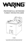
1
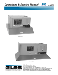
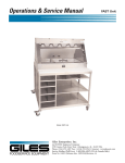
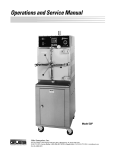
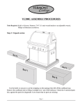
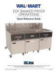
Operations & Service Manual
RT-5
Model: RT-5
Giles Enterprises, Inc.
FOODSERVICE EQUIPMENT
An ISO9001 Registered Company
2750 Gunter Park Drive West • Montgomery, AL 36109 USA
Phone: (334) 272-1457 Fax: • (334) 272-3561 • Internet: www.gilesent.com
Service Hotline (Toll Free): 1-800-554-4537 (USA & Canada Only)
Form No. 63380 (Release date: 02/04/2005)(Revision Level: B)
LIMITED WARRANTY
•
Subject to the terms and conditions of this Limited Warranty as herein stated, all Giles Enterprises,
Inc., Foodservice Equipment and parts purchased new from an authorized Giles Enterprises, Inc.,
representative are warranted as to defects in material or workmanship for a period of 12 months
from the date of installation, provided, however, that with regard to labor costs in connection with
this warranty, see below. All installations must be made by a qualified installing agency in accordance with all applicable codes and/or regulations in the jurisdiction in which installed. Limited warranty coverage is extended to the original owner only and is void if the unit is resold.
•
During the Limited Warranty period, Giles Enterprises, Inc. will replace or recondition, at its factory,
any part or parts of this unit which Giles Enterprises, Inc. inspectors judge defective, provided the
unit has been subjected to normal usage, properly installed, operated and serviced. This Limited
Warranty does not cover cosmetic damage, and damage due to acts of God, accident, misuse, alteration, negligence, abuse of the Giles Foodservice Equipment or the use of unorthodox repair methods. All parts replaced under this Limited Warranty carry only the unexpired term of this Limited
Warranty. Limited Warranty service may be furnished only by an authorized Giles Enterprises, Inc.,
representative.
•
If Limited Warranty service is requested, Giles Enterprises, Inc., will send factory-authorized service representatives to repair, recondition, replace or inspect units of its manufacture with such labor
being rendered without cost to owner for ninety (90) days from the date of installation. Otherwise,
service, including labor and transportation charges or other expenses, in connection with the
removal or installation of any part or parts supplied under this Limited Warranty, are specified on the
original sales contract between the purchaser and the authorized Giles Enterprises, Inc., representative.
•
Giles Enterprises, Inc. reserves the right to change or improve its equipment and parts in any way
without obligation to alter such equipment or parts previously manufactured.
•
Giles Enterprises, Inc. makes no further warranties, express or implied including implied warranties
of merchantability or fitness for a particular purpose, and has no other obligation or liability not
specifically stated herein.
•
Repair or replacement as provided under this Limited Warranty is the exclusive remedy. Giles
Enterprises, Inc., shall not be liable for any incidental or consequential damages for breach of any
express or implied warranty on this product, except to the extent prohibited by applicable law. Any
implied warranty of merchantability or fitness for a particular purpose on this product is limited in
duration to the duration of this Limited Warranty.
•
Used Giles Enterprises, Inc., Foodservice Equipment or parts or Giles Enterprises, Inc., Foodservice
Equipment or parts not purchased from an authorized Giles Enterprises, Inc., representative, carry
no warranties, express or implied.
Table Of Contents
Safety
Model: RT-5
........................................................v
Safety Overview . . . . . . . . . . . . . . . . . . . . . . . . . . . . . . . . . . . . . . . . . . . . . . . . . . . . . . . . . . . . . . . . . . . . v
Specific Safety Precautions . . . . . . . . . . . . . . . . . . . . . . . . . . . . . . . . . . . . . . . . . . . . . . . . . . . . . . . . . . . vi
1.
Introduction . . . . . . . . . . . . . . . . . . . . . . . . . . . . . . . . . . . . . . . . . . . . . . 1
1-01.
1-02.
1-03.
1-03.1.
1-03.2.
1-03.3.
1-03.4.
1-04.
Construction . . . . . . . . . . . . . . . . . . . . . . . . . . . . . . . . . . . . . . . . . . . . . . . . . . . . . . . . . . . . . . 1
Standard Features. . . . . . . . . . . . . . . . . . . . . . . . . . . . . . . . . . . . . . . . . . . . . . . . . . . . . . . . . . 1
Specifications . . . . . . . . . . . . . . . . . . . . . . . . . . . . . . . . . . . . . . . . . . . . . . . . . . . . . . . . . . . . . 2
Overall Dimensions for RT-5 . . . . . . . . . . . . . . . . . . . . . . . . . . . . . . . . . . . . . . . . . . . . . . . . . . 2
Regulatory Listings . . . . . . . . . . . . . . . . . . . . . . . . . . . . . . . . . . . . . . . . . . . . . . . . . . . . . . . . . 3
Unit Weights . . . . . . . . . . . . . . . . . . . . . . . . . . . . . . . . . . . . . . . . . . . . . . . . . . . . . . . . . . . . . . 3
Shipping Specifications (Crated) . . . . . . . . . . . . . . . . . . . . . . . . . . . . . . . . . . . . . . . . . . . . . . . 3
Product Capacity. . . . . . . . . . . . . . . . . . . . . . . . . . . . . . . . . . . . . . . . . . . . . . . . . . . . . . . . . . . 3
2.
Installation . . . . . . . . . . . . . . . . . . . . . . . . . . . . . . . . . . . . . . . . . . . . . . . 5
2-01.
2-02.
2-03.
2-04.
2-05.
2-05.1.
2-05.2.
Unpacking . . . . . . . . . . . . . . . . . . . . . . . . . . . . . . . . . . . . . . . . . . . . . . . . . . . . . . . . . . . . . . . . 5
Location and Clearances. . . . . . . . . . . . . . . . . . . . . . . . . . . . . . . . . . . . . . . . . . . . . . . . . . . . . 6
Leg Installation . . . . . . . . . . . . . . . . . . . . . . . . . . . . . . . . . . . . . . . . . . . . . . . . . . . . . . . . . . . . 7
Table or Counter Installation . . . . . . . . . . . . . . . . . . . . . . . . . . . . . . . . . . . . . . . . . . . . . . . . . . 8
Electrical Requirements . . . . . . . . . . . . . . . . . . . . . . . . . . . . . . . . . . . . . . . . . . . . . . . . . . . . . 9
Electrical Specifications . . . . . . . . . . . . . . . . . . . . . . . . . . . . . . . . . . . . . . . . . . . . . . . . . . . . . 9
Electrical Connections. . . . . . . . . . . . . . . . . . . . . . . . . . . . . . . . . . . . . . . . . . . . . . . . . . . . . . 10
3.
Overview . . . . . . . . . . . . . . . . . . . . . . . . . . . . . . . . . . . . . . . . . . . . . . . 13
3-01.
3-02.
Components . . . . . . . . . . . . . . . . . . . . . . . . . . . . . . . . . . . . . . . . . . . . . . . . . . . . . . . . . . . . . 14
Accessories. . . . . . . . . . . . . . . . . . . . . . . . . . . . . . . . . . . . . . . . . . . . . . . . . . . . . . . . . . . . . . 16
4.
Operation . . . . . . . . . . . . . . . . . . . . . . . . . . . . . . . . . . . . . . . . . . . . . . . 17
4-01.
4-02.
4-03.
4-04.
4-05.
4-06.
4-07.
4-08.
4-09.
4-10.
4-11.
4-12.
4-13.
4-14.
4-15.
4-16.
Cooking Controller buttons and functions . . . . . . . . . . . . . . . . . . . . . . . . . . . . . . . . . . . . . . 18
Setting and running a Manual Menu . . . . . . . . . . . . . . . . . . . . . . . . . . . . . . . . . . . . . . . . . . 20
Programming a Programmed Menu . . . . . . . . . . . . . . . . . . . . . . . . . . . . . . . . . . . . . . . . . . . 22
Running a Programmed Menu . . . . . . . . . . . . . . . . . . . . . . . . . . . . . . . . . . . . . . . . . . . . . . . 23
Cancelling a Manual or Programmed Menu . . . . . . . . . . . . . . . . . . . . . . . . . . . . . . . . . . . . . 24
Viewing actual temperature in Rotisserie . . . . . . . . . . . . . . . . . . . . . . . . . . . . . . . . . . . . . . . 24
Using the Hand-Held Temperature Probe . . . . . . . . . . . . . . . . . . . . . . . . . . . . . . . . . . . . . . . 25
Spit installation . . . . . . . . . . . . . . . . . . . . . . . . . . . . . . . . . . . . . . . . . . . . . . . . . . . . . . . . . . . 26
Basket installation. . . . . . . . . . . . . . . . . . . . . . . . . . . . . . . . . . . . . . . . . . . . . . . . . . . . . . . . . 27
Spit removal . . . . . . . . . . . . . . . . . . . . . . . . . . . . . . . . . . . . . . . . . . . . . . . . . . . . . . . . . . . . . 28
Basket removal . . . . . . . . . . . . . . . . . . . . . . . . . . . . . . . . . . . . . . . . . . . . . . . . . . . . . . . . . . . 29
Spit Wheel Assembly removal . . . . . . . . . . . . . . . . . . . . . . . . . . . . . . . . . . . . . . . . . . . . . . . 30
Spit Wheel Assembly installation . . . . . . . . . . . . . . . . . . . . . . . . . . . . . . . . . . . . . . . . . . . . . 31
Normal Shut-Down . . . . . . . . . . . . . . . . . . . . . . . . . . . . . . . . . . . . . . . . . . . . . . . . . . . . . . . . 32
Emergency Shut-Down. . . . . . . . . . . . . . . . . . . . . . . . . . . . . . . . . . . . . . . . . . . . . . . . . . . . . 32
Recipes . . . . . . . . . . . . . . . . . . . . . . . . . . . . . . . . . . . . . . . . . . . . . . . . . . . . . . . . . . . . . . . . . 33
iii
Model: RT-5
Table Of Contents
5.
Cleaning . . . . . . . . . . . . . . . . . . . . . . . . . . . . . . . . . . . . . . . . . . . . . . . . 35
5-01.
5-02.
5-03.
Cleaning the Inner Cabinet . . . . . . . . . . . . . . . . . . . . . . . . . . . . . . . . . . . . . . . . . . . . . . . . . . 35
Cleaning the Outer Cabinet . . . . . . . . . . . . . . . . . . . . . . . . . . . . . . . . . . . . . . . . . . . . . . . . . 36
Cleaning the Glass Doors . . . . . . . . . . . . . . . . . . . . . . . . . . . . . . . . . . . . . . . . . . . . . . . . . . . 37
6.
Troubleshooting . . . . . . . . . . . . . . . . . . . . . . . . . . . . . . . . . . . . . . . . . 39
6-01.
Troubleshooting Procedures . . . . . . . . . . . . . . . . . . . . . . . . . . . . . . . . . . . . . . . . . . . . . . . . . 39
7.
Parts List . . . . . . . . . . . . . . . . . . . . . . . . . . . . . . . . . . . . . . . . . . . . . . . 43
7–01.
7-02.
7-03.
7-04.
7-05.
7-06.
7-07.
7-08.
7-09.
7-10.
7-11.
7-12.
Parts Ordering and Service Information . . . . . . . . . . . . . . . . . . . . . . . . . . . . . . . . . . . . . . . . 43
Quartz Light Replacement . . . . . . . . . . . . . . . . . . . . . . . . . . . . . . . . . . . . . . . . . . . . . . . . . . 44
Fuse Replacement . . . . . . . . . . . . . . . . . . . . . . . . . . . . . . . . . . . . . . . . . . . . . . . . . . . . . . . . 44
Spit Wheel Assembly . . . . . . . . . . . . . . . . . . . . . . . . . . . . . . . . . . . . . . . . . . . . . . . . . . . . . . 46
Spit Wheel Support Replacement . . . . . . . . . . . . . . . . . . . . . . . . . . . . . . . . . . . . . . . . . . . . 46
Drive Motor Replacement . . . . . . . . . . . . . . . . . . . . . . . . . . . . . . . . . . . . . . . . . . . . . . . . . . 48
Drive Motor Assembly . . . . . . . . . . . . . . . . . . . . . . . . . . . . . . . . . . . . . . . . . . . . . . . . . . . . . 48
Element and Probe Replacement. . . . . . . . . . . . . . . . . . . . . . . . . . . . . . . . . . . . . . . . . . . . . 50
Blower Replacement . . . . . . . . . . . . . . . . . . . . . . . . . . . . . . . . . . . . . . . . . . . . . . . . . . . . . . 52
Component Replacement. . . . . . . . . . . . . . . . . . . . . . . . . . . . . . . . . . . . . . . . . . . . . . . . . . . 54
Controller Assembly . . . . . . . . . . . . . . . . . . . . . . . . . . . . . . . . . . . . . . . . . . . . . . . . . . . . . . . 54
Door Replacement . . . . . . . . . . . . . . . . . . . . . . . . . . . . . . . . . . . . . . . . . . . . . . . . . . . . . . . . 56
8.
Wiring Diagram . . . . . . . . . . . . . . . . . . . . . . . . . . . . . . . . . . . . . . . . . . 59
8-01.
8-02.
8-03.
8-04.
8-05.
Wiring
Wiring
Wiring
Wiring
Wiring
iv
Diagram
Diagram
Diagram
Diagram
Diagram
RT-5
RT-5
RT-5
RT-5
RT-5
208-240/60/1. . . . . . . . . . . . . . . . . . . . . . . . . . . . . . . . . . . . . . . . . . . . 60
208-240/60/3. . . . . . . . . . . . . . . . . . . . . . . . . . . . . . . . . . . . . . . . . . . . 62
230/50/1 . . . . . . . . . . . . . . . . . . . . . . . . . . . . . . . . . . . . . . . . . . . . . . . 64
380/50/3 . . . . . . . . . . . . . . . . . . . . . . . . . . . . . . . . . . . . . . . . . . . . . . . 66
415/50/3 . . . . . . . . . . . . . . . . . . . . . . . . . . . . . . . . . . . . . . . . . . . . . . . 68
Safety
Model: RT-5
Safety
Safety Overview
The instructions contained in this manual have been prepared to assist you in learning the proper procedures for installing and servicing your unit.
Throughout this manual, safety precautions are identified through the use of the safety alert symbol and
three signal words: DANGER, WARNING, and CAUTION. All safety alert information precedes the
step(s) to which they apply. Suggested, recommended, or other noteworthy information is identified
through the use of NOTES. Additionally, certain words are used to indicate a specific meaning or to add
emphasis.
The following words are used as indicated throughout the manual:
Shall: understood to be mandatory.
Should: understood to be advisory.
May: understood to be permissive.
Will: indicates a future event/condition to occur.
! or !
(Safety Alert Symbol)
Used in conjunction with signal words (DANGER, WARNING, or CAUTION) to alert you of potential personal injury hazards, immediately preceding precautionary measures that pertain to subsequent step(s).
Obey all safety messages that follow this symbol to avoid possible injury or death. Failure to adhere to
safety precautions identified by the safety alert symbol may also void the warranty.
!
DANGER
• Indicates an imminently hazardous situation which, if not avoided, will result in death or serious injury.
Use of this is limited to the most extreme situations.
! WARNING
• Indicates a potentially hazardous situation which, if not avoided, could result in death or serious injury.
! CAUTION
• Indicates a potentially hazardous situation which, if not avoided, may result in minor or moderate injury.
Also used to alert against unsafe practices.
CAUTION
• When used without the safety alert symbol, CAUTION indicates a potentially hazardous situation
which, if not avoided, may result in equipment/property damage, and void the warranty.
NOTE:
• Identifies suggested, recommended, or other noteworthy information.
v
Model: RT-5
Safety
Specific Safety Precautions
For your safety, please observe the following precautions when operating or servicing the Giles Rotisserie
Model RT-5. Read the following important safety information to avoid personal injury and/or damage to
the equipment.
!
DANGER
• Always disconnect the source of the main power before removing any service covers.
• Failure to comply with these DANGER notices will result in death or serious injury, equipment/property
damage, and void the warranty.
! WARNING
• DO NOT use or store gasoline or other flammable liquids or vapors in the vicinity of this or any other
appliance!
• Consult a qualified electrician to ensure all electrical specifications have been met and the unit is properly grounded.
• Before installing or servicing this equipment, read the contents of this manual thoroughly.
• Improper installation, adjustment, alteration, service or maintenance could result in death or serious
injury, equipment/property damage, and void the warranty.
• Exercise care when lifting or moving the unit. For unit weights see Section 1-03.3.
• Exercise care when removing the wooden crate from around the unit.
• DO NOT CLEAN OR TOUCH the quartz lights located in top of the RT-5 doors.
• DO NOT CLEAN GLASS WHEN HOT! Clean glass with approved cleaner, do not use abrasive on
glass!
• Failure to comply with these WARNING notices could result in death or serious injury and
equipment/property damage.
vi
Safety
Model: RT-5
CAUTION
• Do not operate the RT-5 unless you fully understand all it’s components and their intended functions.
• The electronic components of the Control Panel are impact-sensitive.
Exercise care around the Control
Panel to maintain proper operation.
• During cleaning of unit.
••
••
••
••
DO
DO
DO
DO
NOT
NOT
NOT
NOT
steam clean.
use products containing chlorine.
use abrasive products, steel wool or scouring pads.
USE OVEN CLEANER.
• DO NOT CLEAN OR TOUCH the quartz lights located in top of the RT-5 doors.
• Failure to comply with these CAUTION notices may result in equipment/property damage and void the
warranty.
NOTE:
• If the Shipping Crate is damaged, immediately inspect the unit and notify the carrier of any damage to
the unit.
• To aid the electrician, an electrical wiring diagram is contained in this manual.
Refer to the wiring dia-
gram during installation or servicing.
• Comply with all appropriate state and/or local heath regulations regarding the cleaning and sanitation of
equipment.
• For difficult to clean areas, a mild biodegradable nontoxic degreaser (such as Clear Magic or Simple
Green) may be used.
• Always ensure the unit is electrically grounded and installed in accordance with local codes, or in the
absence of local codes, in accordance with the National Electrical Code ANSI/NFPA No. 70-1984.
vii
Model: RT-5
Notes:
viii
Safety
Introduction
1.
Model: RT-5
Introduction
Congratulations on the purchase of your new Giles Rotisserie Model RT-5, manufactured by Giles
Enterprises, Inc., Montgomery, Alabama (USA).
To help protect your investment in this equipment, we recommend taking a few moments to familiarize
yourself with the installation, cleaning and maintenance procedures contained in this manual. Read these
instructions before installation and use. Adherence to these recommended procedures minimizes the
potential for costly "down-time" and equipment repairs. Please retain this manual for future reference.
1-01.
Construction
The RT-5, is constructed of a stainless steel frame and uses tempered glass in the doors.
1-02.
Standard Features
Control Panel
• Controls are functional, easy to operate.
Temperature Controls
• Adjustable control up to 420ºF (215.5ºC).
• 10 programmable menus.
Doors
• Curved glass provides panoramic view of product.
• Both front and rear doors provide easy access for loading and cleaning.
1
Model: RT-5
1-03.
Introduction
Specifications
The following sections give various specifications of the RT-5.
1-03.1. Overall Dimensions for RT-5
Customer-side Door
Operator-side Door
INCHES [MILLIMETERS]
2
Introduction
Model: RT-5
1-03.2. Regulatory Listings
UL (US and Canada)
NSF
CE
1-03.3. Unit Weights
Unit
Crated Weight
Uncrated Weight
(without product)
RT-5
314 lbs [142.4 kg]
209 lbs [94.8 kg]
1-03.4. Shipping Specifications (Crated)
Net Weight
Crated Size
Model
Length
Lbs
RT-5
1-04.
314
Volume
Width
Height
In
mm
In
mm
In
mm
Cubic
Feet
54
1371.6
36
914.4
42
1066
47.25
Kg
142.4
Cubic
Meters
1.338
Product Capacity
Product
Weight (lb)
Weight (kg)
Quantity
Whole Chicken
2-1/2 to 2-3/4
1.13 to 1.24
20
Ribs
3 to 3-1/2
1.36 to 1.58
5
Roast
5
2.26
5
3
Model: RT-5
Notes:
4
Introduction
Installation
Model: RT-5
2. Installation
This section provides a summary of procedures necessary to install your new Giles Rotisserie,
Model RT-5. Before installing or servicing this equipment, please read the contents of this manual
thoroughly. Following these procedures will help ensure a safe and proper installation.
2-01. Unpacking
Your unit should arrive packaged in a wooden crate, covered with plastic shipping wrap, and secured to a
wooden platform by means of high-tensile strength strapping. Perform the following steps to uncrate the
unit:
NOTE:
• If the crate is damaged, immediately inspect the unit and notify the carrier of any damage to the unit.
! CAUTION
•
Exercise care when lifting or moving the unit, please see Section 1-03.3 for unit weights.
•
Exercise care when removing the wooden crate from around the unit.
1. Position the packaged RT-5 in an area with sufficient room for unpacking.
2. Cut and remove the plastic shipping wrap and any high-tensile strength straps from the exterior of the
wooden crate.
3. Carefully use a hammer and pry bar to remove the wooden crate from around the unit.
4. Cut and remove the plastic shipping wrap and high-tensile strength strapping that secures the unit to
the wooden platform.
5. Before installing, check the unit for damage. If unit was damaged during shipment, notify the carrier
immediately and file a claim.
6. Carefully remove the unit from the wooden platform and place at the installation site.
7.
Using wire cutters, cut all plastic ties holding Spits or Baskets and Spit Wheel Assembly in place.
5
Model: RT-5
Installation
2-02. Location and Clearances
! WARNING
• DO NOT install the unit next to combustible walls or materials.
Failure to maintain safe distances may result in
combustion.
• DO NOT MODIFY, ALTER OR ADD ATTACHMENTS TO THIS EQUIPMENT.
1. Select a location with adequate space to properly operate and service the RT-5.
2. A minimum clearance of 4 inches from the side of the RT-5 to any obstruction is required for
adequate ventilation through the unit. See below for proper clearances.
3. Mount the RT-5 on a Table or Counter that is capable of safely bearing it’s weight
and the maximum weight of product to be placed in the unit for cooking.
4. Place the RT-5 with Customer-side Door facing the customer and the Operator-side Door facing the
operator.
Operator-side Door
Inches [Millimeters]
6
Customer-side Door
Installation
Model: RT-5
2-03. Leg Installation
1. Fasten Legs and Leg Mounts to the unit. Ensure the Leg Mounts are diagonal to each other to
stabilize the unit. See below
Leg Mount
Leg Mount
7
Model: RT-5
Installation
2-04. Table or Counter Installation
! WARNING
• Ensure the Table or Counter can adequately maintain the weight of the unit (See Section 1.03.3
for unit weights) and the weight of the product being cooked.
1. Place the unit on an adequate table or counter. Ensure the table or counter can maintain the weight of
the unit with a full load of product.
2. Ensure the unit is level. To help level the unit rotate the lower part of the adjustable legs clockwise or
counter-clockwise.
3. Using screws appropriate to the table or counter (not supplied), fasten (2) Leg Mounts with (3) screws
per mount, into the table or counter.
Leg Mount
Lower Leg Adjustment
(3) Screws per mount (Screws
supplied by customer)
8
Installation
Model: RT-5
2-05. Electrical Requirements
The following sections describe various electrical specifications and connections for the RT-5.
! WARNING
• The unit must be adequately and properly grounded. Improper grounding may result in electrical
shock. Always refer to your local electrical code to ensure proper grounding of this or any other
electrical equipment. Always consult with an electrician or other qualified service person to ensure
breakers and wiring are of sufficient rating and gauge for the equipment being operated.
2-05.1.
Electrical Specifications
Please see the Serial Plate attached to the RT-5, for the proper Voltage, Hz, and Phase of the unit.
L1
L2
L3
Circuit
Breaker
Required
(amps)
AMPS
Model
Voltage
Hz
Phase
Watts
RT-5
208
60
1
6,160
29.6
29.6
--
40
RT-5
208
60
3
6,160
13.1
21.6
17.7
30
RT-5
240
60
1
6,160
25.6
25.6
--
40
RT-5
240
60
3
6,160
11.3
18.7
15.5
30
RT-5
230
50
3
6,160
11.3
18.7
15.5
30
RT-5
380
50
3
6,160
9.0
4.4
13.4
20
RT-5
415
50
3
6,160
8.7
4.2
12.8
20
9
Model: RT-5
2-05.2.
Installation
Electrical Connections
1.
Install appropriate Circuit Breakers in Main Breaker Box. See Table 2-05.1.
2.
Connect appropriate size Power Cable for the Voltage and Phase being used, to the Main Breaker.
Allow enough Power Cable so the unit can be moved for cleaning and servicing.
3.
Remove the Side Cover and Probe Holders.
Side Cover
Probe Holders
4.
Fasten Cable or Conduit to the unit using customer supplied Cord Strain Relief or Cable Connector.
5.
Connect Grounding Wire to the unit’s Ground Lug.
6.
Connect appropriate Power wires to the unit’s Contactor.
Contactor
L3 for 3 phase only
L1 L3 L2
Main
Breakers
Power
Wires
Ground
Lug
Ground
Wire
(Continued next page)
10
Installation
2-05.2.
Model: RT-5
Electrical Connections (Continued for previous page)
7.
Reinstall Side Cover and Probe Holders.
8.
Ensure all plastic ties holding Spits or Baskets and Spit Wheel Assembly have been removed.
9.
Turn Main Breaker on.
10.
Press the Power Switch to the ON 1 position. Verify the unit’s lights (Customer-side only) and the
controller illuminate. (Note: The Operator-side Door Light will only illuminate only when the heating
elements are on. The Customer-side Door Light is illuminated when the Power Switch is in the ON
position.)
Lights
1
Controller
11
Model: RT-5
Notes:
12
Installation
Overview
Model: RT-5
3. Overview
The following section provides a brief overview of the components, functions, and accessories of the
RT-5. Please review this section carefully before proceeding any further.
13
Model: RT-5
Overview
3-01. Components
4. Power Switch
2. Spit Wheel
Assembly
3. Controller
1. Operator-side Door
5. Customer-side Door
6. Spit or *Basket
7. Grease Funnel
8. Drip Pan
9. Hand-Held Temperature Probe
* - Not shown
14
Overview
Model: RT-5
3-01. Components
Item
Description
Function
1
Operator-side Door
Used to load and unload Product. Also used for easy access
when cleaning the unit.
2
Spit Wheel Assembly
3
Controller
4
Power Switch
5
Customer-side Door
6
Spit or *Basket
7
Drip Funnel
8
Drip Pan
9
Hand-Held Temperature
Probe
Used to support and rotate Spits or Basket.
Used to control cooking cycles (Temperature and Times).
Used to turn power to unit on or off.
Used to allow customers to view the product. Also used for
easy access when cleaning the unit.
Used to support the product being cooked.
Used to funnel Product Drippings to the Drip Pan
Used to catch the Product Drippings.
Used to check the internal temperature of the Product being
cooked.
* - Not shown
15
Model: RT-5
Overview
3-02. Accessories
Part
Description/Part Number
Function
RT-5 Spit
(5 included in Spit model)
P/N 33199
Support Product placed in unit
RT-5 Basket
(5 included in Basket model)
P/N 70203
Support Product placed in unit
Drip Funnel
(1 included)
P/N 33102
Drip Pan
(1 included)
P/N 76024
16
Used to funnel the product
drippings to the Grease Drip
Pan
Used to capture
product drippings
Operation
Model: RT-5
4. Operation
This section describes how to operate the unit.
17
Model: RT-5
Operation
4-01. Cooking Controller buttons and functions
This section describes how to operate the Cooking Controller.
Cooking Controller
Hand-Held Temperature Probe
18
Operation
Model: RT-5
4-01. Cooking Controller buttons and functions
This section describes the basic function of each button on the controller.
Used to display Times, Temperatures and
other various messages.
Used for setting and displaying Cooking and Holding Temperature.
Used for setting and displaying Cooking and Holding Time.
Used to select a programmed menu (Cooking Cycle).
Used for starting and stopping a menu (Cooking Cycle).
Used to increase Time and Temperature; to select programmed
menus 1-10; and to rotate the internal spits when the door is open.
Used to decrease Time and Temperature; to select programmed
menus 1-10; and to activate the Hand-Held Temperature Probe (Only
when Operator-side door is open).
19
Model: RT-5
Operation
4-02. Setting and running a Manual Menu
This section describes how to set and run a Manual Menu (A Non-Programmed Menu). The Manual Menu
controls Cooking Temperature, Holding Temperature, and Cooking Time. The Manual Menu program will
not be saved once the power is turned off.
Step 2
Step 1
Power
On
Step 3
Step 4
Press to begin setting
Cooking Temp
Display reads
Display reads
After pressing you have 5
seconds to proceed to the
next step or the controller
will return to the idle state.
Step 6
Step 5
Press to Adjust
Cooking Temperature
Cooking Temp
is displayed
Step 7
Step 8
Press to begin setting
Holding Temp
Display reads
or
After adjusting you have 5
seconds to proceed to
Step 7 or the controller will
return to the idle state.
After pressing you have 5
seconds to proceed to
Step 9 or the controller will
return to the idle state.
Step 10
Step 9
Press to Adjust
Holding Temperature
Holding Temp
is displayed
Step 11
Press to begin setting
Cooking Time
Step 12
Press to Adjust
Cooking Time
or
or
After adjusting you have 5
seconds to proceed to
Step 11 or the controller will
return to the idle state.
After pressing you have 5
seconds to proceed to
Step 12 or the controller will
return to the idle state.
Continued next page
20
Operation
Model: RT-5
4-02. Setting and running a Manual Menu (Continued from previous page)
Step 13
Cooking Time
is displayed
Step 14
Press to Start
Pre-Heat
RT-5 begins PreHeating and Spit
Wheel begins rotating
Step 17
Load Product
See Section 4-08. for
loading Spits.
Step 18
Press to Start
Cooking Time
Step 15
Display reads.
Display reads.
then displays the
actual temperature
inside the RT-5 until
Pre-Heated
Step 19
Cooking Time
begins counting
down
Holding Time
begins counting.
Unit is now
ready for product
Step 20
At the end of the
Cooking Time, the
unit cycles to the
Holding Temperature
Display reads
See Section 4-09. for
loading Baskets
Step 21
Step 16
Step 22
Open Door and
Unload Product.
(Note: When the
door is open the
Holding Time will
pause.)
Step 23
Press to end the
Manual Menu.
(Note: if not
pressed when the
Door is closed the
Holding Time will
continue.
Step 24
Power may be
turned off or
the Manual
Menu may be
re-started
21
Model: RT-5
Operation
4-03. Programming a Programmed Menu
This section describes how to program a Programmed Menu into the Cooking Controller. A programmed
Menu contains Cooking Temperature, Holding Temperature and Cooking Time. The Menu is saved in the
Controller, even when the unit is turned off. This function is useful when cooking various products at different cooking temperatures and times.. You may program up to 10 Programmed Menus in the RT-5.
Step 1
Step 2
Step 3
Power
On
Display reads
Press to begin
programming
Step 4
Press to find menu
1-10 to program
or
Step 6
Press to begin setting
Cooking Temperature
Step 7
Step 8
Press to adjust
Cooking Temperature
Press to begin setting
Holding Temperature
Step 10
Press to begin setting
Cooking Time
After adjusting you have 5
seconds to proceed to the
next step or the controller
will return to the idle state.
Step 11
or
After pressing you have 5
seconds to proceed to the
next step or the controller
will return to the idle state.
22
After pressing you have 5
seconds to proceed to the
next step or the controller
will return to the idle state.
Step 12
Press to Adjust
Cooking Time
Press to Adjust
Holding Temperature
or
or
After pressing you have 5
seconds to proceed to the
next step or the controller
will return to the idle state.
Step 9
Press to save
the program
to the menu
After adjusting you have 5
seconds to proceed to the
next step or the controller
will return to the idle state.
Operation
Model: RT-5
4-04. Running a Programmed Menu
This section describes how to run a Programmed Menu. If you have not programmed a menu please see
Section 4-03.
Step 1
Step 2
Step 3
Step 4
Press to find
menu 1-10
Power
On
Display reads
Press
or
Step 5
Step 6
Press to Start
Pre-Heat
When Display reads
RT-5 begins PreHeating and Spit
Wheel begins rotating
Step 9
Holding Time
begins counting.
Step 7
Press to Start
Cooking Time
Step 8
At the end of the
Cooking Time, the
unit cycles to the
Holding Temp.
Display reads
Open Door and Load
Product
Step 10
Open Door and
Unload Product.
(Note: When the door
is open the Holding
Time will pause.)
Step 11
Press to end the
Menu. (Note: if not
pressed when the
Door is closed the
Holding Time will
continue.
23
Model: RT-5
Operation
4-05. Cancelling a Manual or Programmed Menu
This section describes how to cancel a Manual or Programmed Menu.
Step 1
During a Cooking
Cycle, Press and
Hold for 3 seconds
Step 2
Display reads.
Program has been
cancelled.
4-06. Viewing actual temperature in Rotisserie
This section describes how to view the actual temperature in the Rotisserie.
Step 1
During a Cooking
Cycle, Press and Hold.
24
Step 2
After 3 seconds the
Actual Temperature is
displayed until Temp
Button is released
Operation
Model: RT-5
4-07. Using the Hand-Held Temperature Probe
This section describes how to use the Hand-Held Temperature Probe. The Probe is used to check the internal temperature of the product being cooked.
Step 2
Step 1
The Rotisserie
door must be
open to enable
the Probe Temp
mode.
Step 3
Press
Display reads
Step 5
Step 4
Insert Probe into Product
Internal
Temperature
is display
Step 7
Step 6
Remove Probe from Product
The Jog button may be
used to manually rotate
the Spits or Baskets
while the door is open.
Step 8
Close the
Rotisserie door.
If running a
Menu the
Cooking Time
will resume.
25
Model: RT-5
Operation
4-08. Spit installation
This section describes how to install the Spits. Always place a Spit through the Product before installing
the Spits into the Spit Wheel. (Note: Product to be cooked not shown in illustration)
Step 1
Place Pointed End through
Left Spit Wheel Holes
Operator-side Door
Step 2
Operator-side Door
Place Bottom Grooved End into Right Spit Wheel
Step 3
Use Jog button
to rotate Spits
26
Operation
Model: RT-5
4-09. Basket installation
This section describes how to install the Baskets. Product may be placed in the Baskets before or after
installing the Baskets into the Spit Wheel. (Note: Product to be cooked not shown in illustration)
Step 1
Operator-side Door
Place the Non-Grooved End through the
Middle Hole on the Left Spit Wheel
Step 2
Operator-side Door
Place the Grooved End into the Middle Hole on Right Spit Wheel
Step 3
Use Jog button
to rotate Baskets
27
Model: RT-5
Operation
4-10. Spit removal
This section describes how to remove the Spits. Always use Oven Mitts when removing the Spits. (Note:
Product to be cooked not shown in illustration)
Step 1
Operator-side Door
Remove Bottom Grooved End from Right Spit Wheel
Step 2
Remove Pointed End from Left
Spit Wheel Holes
Operator-side Door
Step 3
Use Jog button
to rotate Spits
28
Operation
Model: RT-5
4-11. Basket removal
This section describes how to remove the Baskets. Always use Oven Mitts when removing the Baskets.
(Note: Product to be cooked not shown in illustration)
Step 1
Operator-side Door
Remove the Grooved End from the Right Spit Wheel
Step 2
Operator-side Door
Remove the Non-Grooved End
from the the Left Spit Wheel
Step 3
Use Jog button
to rotate Baskets
29
Model: RT-5
Operation
4-12. Spit Wheel Assembly removal
This section describes how to remove the Spit Wheel Assembly. Always allow the unit to thoroughly cool
before removing this assembly.
Step 1
Remove the Spits or Baskets. See Sections
4.10. Spit removal or 4.11. Basket removal.
Step 2
Lift the right-side of the Spit Wheel Assembly
Operator-side Door
Step 3
Move the entire Assembly to the right
30
Step 4
Move the entire assembly out of the unit
Operation
Model: RT-5
4-13. Spit Wheel Assembly installation
This section describes how to install the Spit Wheel Assembly.
Step 1
Move the entire assembly into the unit
Step 2
Move the entire Assembly to the right
Operator-side Door
Step 3
Align groove in Left-side support with Spit
Wheel Spoke.
Step 4
Lower right-side into Right-side support
cradle.
31
Model: RT-5
Operation
4-14. Normal Shut-Down
1
1. Press the Power Switch to the OFF 1 position.
4-15. Emergency Shut-Down
In case of emergency, remove power to the unit by turning off the facility circuit breaker.
32
Operation
Model: RT-5
4-16. Recipes
Cook Time or
Pre-Heat
Cook
Internal
until internal
Temperature Temperature temperature Temperature
is reached
Product
Product
Specifications
Accessory
Whole
Chicken
2.5lb to 2.75lb
1.23kg to 1.24kg
Spits or
Baskets
350°F
177°C
350°F
177°C
70
minutes
180°F
82°C
Chicken
Halves
Cut from
2.5lb to 2.75lb
1.23kg to 1.24kg
Baskets
350°F
177°C
350°F
177°C
45
minutes
180°F
82°C
Chicken
Quarters
Cut from
2.5lb to 2.75lb
1.23kg to 1.24kg
Baskets
350°F
177°C
350°F
177°C
45
minutes
180°F
82°C
Chicken
Pieces
Cut from
2.5lb to 2.75lb
1.23kg to 1.24kg
Baskets
350°F
177°C
350°F
177°C
40
minutes
180°F
82°C
Ribs
3lb to 3.5lb
1.4kg to 1.6kg
Spits or
Baskets
400°F
204°C
400°F
204°C
45
minutes
155°F
68°C
Boston
Butt
5lb
2.3kg
Spits or
Baskets
400°F
204°C
400°F
204°C
45
minutes
155°F
68°C
Rolled
Beef Roast
5lb
2.3kg
Spits or
Baskets
400°F
204°C
400°F
204°C
45
minutes
155°F
65°C
Baskets
400°F
204°C
400°F
204°C
45
minutes
145°F (rare)
63°C (rare)
Salmon
Steaks
33
Model: RT-5
Notes:
34
Operation
Cleaning
Model: RT-5
5. Cleaning
This section describes the cleaning of the unit.
5-01. Cleaning the Inner Cabinet
! CAUTION
• Place the Power Switch in the OFF position and allow unit to thoroughly cool before following
this procedure.
• DO NOT Steam Clean the unit.
• DO NOT use cleaning products containing chlorine.
• DO NOT use abrasive products, steel wool or scouring pads.
• DO NOT USE OVEN CLEANER.
• DO NOT CLEAN OR TOUCH quartz lights located in top of unit doors.
For difficult areas use a biodegradable nontoxic degreaser, such as Clear Magic or Simple Green.
Step 1
Step 2
Remove Spits or Baskets and Spit Wheel
then clean separately. See Sections 4.12
Spit Wheel Assembly Removal.
Remove Drip Funnel then clean. Begin
cleaning the inside of the unit. The
Customer-side Door may be opened to
allow easy access to the inside of the
unit.
Continued next page
35
Model: RT-5
Cleaning
5-01. Cleaning the Inner Cabinet (Continued from previous page)
Step 3
Remove Grease Drip Pan and clean.
Step 4
Re-assemble unit.
5-02. Cleaning the Outer Cabinet
Clean exterior of the unit using a mild non-abrasive detergent. Polish the stainless steel with an approved
stainless steel cleaner.
36
Cleaning
Model: RT-5
5-03. Cleaning the Glass Doors
! CAUTION
• DO NOT CLEAN OR TOUCH quartz lights located in top of unit doors.
• DO NOT CLEAN GLASS WHEN HOT! Clean glass with approved cleaner, do not use abrasive on
glass!
Clean both sides of glass with an approved cleaner, do not use abrasives on glass!
37
Model: RT-5
Notes:
38
Cleaning
Troubleshooting
Model: RT-5
6.Troubleshooting
!
•
•
DANGER
Electrical troubleshooting procedures should be done ONLY by qualified service personnel. Death or
serious injury will result from contact with energized electrical components.
Failure to comply with these DANGER notices will result in death or serious injury, equipment/property damage, and void the warranty.
6-01. Troubleshooting Procedures
Problem
Rotisserie will not turn
on.
No display on the
Controller. Quartz Lamps
not illuminated.
Probable Cause
a. Unit not connected to power
source.
a. Call service technician to connect
to proper power source.
b. Defective fuse or circuit breaker.
b. Check fuse or circuit breaker. Call
service technician to replace faulty
fuse or circuit breaker.
c. Fuse holder cracked.
c. Call service technician to replace
fuse holder.
d. Call service technician to replace
POWER switch.
d. POWER switch defective
Rotisserie will not heat
Repair Procedure
e. Improper supply voltage
e. Call service technician to connect
proper supply voltage.
a. Check to verify temp is set.
a. Check cooking set-point.
b. Loose wire
Heat indicator on
Controller is illuminated
and the display indicating c. Bad element
temperature
d. Bad contactor
b. Call service technician to reposition
wire.
c. Call service technician to replace
element.
d. Call service technician to replace
contactor.
e. Bad controller
e. Call service technician to replace
controller.
f.
f.
High limit module
Call service technician to replace
high limit module.
g. Temperature probes
g. Call service technician to replace
temperature probes.
h. Door switch
h. Call service technician to replace
door switch.
i.
i.
Elements and Quartz Lamp
Call service technician to replace
elements and quartz lamps
39
Model: RT-5
Troubleshooting
6-01. Troubleshooting Procedures
Problem
Quarts Lamps not Illuminated
Probable Cause
a. Bad quartz lamp
One or both Lamps not illuminated
b. Loose wire
when Controller Heat indicator is
illuminated and Elements are heating.
c. Bad contactor
Rotisserie shuts down with
Power Switch in ON position
Spit Wheel Assembly Not
Rotating
40
Repair Procedure
a. Call service technician to replace
quartz lamp.
b. Call service technician to replace
wiring.
c. Call service technician to replace
contactor.
a. High limit exceeded
a. Cool unit. If unit exceeds high temp
limit continuously, call service technician.
b. Bad safety contactor
b. Call service technician to replace
contactor.
c. Bad safety probe
c. Call service technician to replace
safety probe.
d. Door switches
d. Verify door is closed
completely. Possible bad door
switch.
a. Motor bad
a. Call service technician to replace
faulty motor.
b. Chain loose
b. Call service technician to
tighten chain.
c. Motor hot
c. Cool motor, if problem persists call
service technician.
d. Faulty load relay
d. Call service technician to replace
faulty load relay.
e. Loose wiring
e. Call service technician to replace
loose wiring.
f.
f.
Bad Controller
Call service technician to replace
Controller.
g. Left wheel support
screw loose.
g. Tighten Screw.
h. Door Open
h. Close Door
i.
i.
Door Switch bad
Call service technician to replace
faulty door switch.
Troubleshooting
Model: RT-5
6-01. Troubleshooting Procedures
Problem
Blower Not Working
Elements & quartz lamps working
Product is slow to cook
Probable Cause
a. Bad fan motor
a. Call service technician to
replace fan motor.
b. Faulty capacitor
b. Call service technician to
replace faulty capacitor.
c. Loose wiring.
c. Call service technician to
repair loose wiring.
a. Elements or Quartz lamps not a. Call service technician to
working
replace either elements or
quartz lamps.
b. Cook temp not set properly
b. Set correct cooking
temperature.
c. Contactor not functioning
c. Call service technician to
replace contactor.
d. Fan is not operating
d. Call service technician to have
fan replaced.
e. Fan running & no air movement
e. Fan blades loose or dirty. Call
service technician.
f.
f. Call service technician.
Temperature calibration
Load Switch will not rotate Spit a. Faulty Controller
Wheel Assembly
Rotates when door is closed
Repair Procedure
a. Call service technician to
replace Controller.
b. Faulty relay
b. Call service technician to
replace relay.
c. Loose wiring
c. Call service technician to
repair wiring.
41
Model: RT-5
Notes:
42
Troubleshooting
Parts List
7.
Model: RT-5
Parts List
This section lists various parts that are available for replacement on the unit.
7–01. Parts Ordering and Service Information
If you require assistance or need repairs, please contact your area developer for a service agency in your
area. For further assistance, please contact the Giles Enterprises, Inc. factory at the following phone
numbers:
IN THE UNITED STATES, CANADA or MEXICO
Please call 1-800-288-1555 during normal business hours, 8:00AM-5:00PM Central Time Zone; for
Emergency Equipment Repair Service, after normal business hours call 1-800-288-1555, extension 314.
IN ALL OTHER COUNTRIES
Please call 1-334-272-3528 during normal business hours, 8:00AM-5:00PM Central Time Zone; for
Emergency Equipment Repair Service, after normal business hours call 1-334-272-3528 extension 314.
INTERNET
Please visit our website on the world wide web at: www.gilesent.com.
The goal of the Giles team of professionals is to provide you with the highest quality of service and assistance. You can help us accomplish this by obtaining the following information and having it readily available when calling. The information is recorded on the Serial Plate attached to the rear of the unit.
Serial Plate
The area below may be helpful in recording information for use as a quick reference.
Model Number: ______________________________________
Serial Number: ______________________________________
Phase:
___________________________________________
Voltage: ___________________________________________
Nature of Problem: _________________________________
43
Model: RT-5
7-02.
Parts List
Quartz Light Replacement
CAUTION
• DO NOT TOUCH quartz lights.
• DO NOT CLEAN quartz lights.
Flat Washer
Flat Washer
Nut
Terminal Cover
Terminal Cover
Screws
7-03.
Fuse Replacement
1
Fuse Holder Cover
44
Nut
1
Terminal Cover
Parts List
7-02.
Model: RT-5
Parts List for Quartz Light Replacement
Item
Part No.
Qty.
1
37808
2
Description
LIGHT, QUARTZ, 1000 WATT
CAUTION
• DO NOT TOUCH quartz lights.
• DO NOT CLEAN quartz lights.
7-03.
Parts List for Fuse Replacement
Item
Part No.
Qty.
1
21875
2
Description
FUSE, 6 AMP, SC-6
45
Model: RT-5
7-04.
Parts List
Spit Wheel Assembly
2
1
3
4
1
7
5
6
7-05.
Spit Wheel Support Replacement
4
5
6
2
1
46
3
Parts List
7-04.
Model: RT-5
Parts List for Spit Wheel Assembly
Item
Part No.
Qty.
1
11500
6
SCREW, 10-32X 1/2, FLT HD SLT, SS
2
35554
1
WHEEL, LEFT SPIT (CR-5)
3
35511
1
WHEEL SPIT SHAFT, WELD ASSY
4
35514
1
WHEEL, RIGHT SPIT (RT-5)
5
34300
1
EXTENSION, WHEEL SHAFT
6
40155
1
BEARING, RULON, 1/2IN ID, RT-5
7
13150
1
RETAINING RING, EXTERNAL, 1/2
7-05.
Description
Parts List for Spit Wheel Support Replacement
Item
Part No.
Qty Description
1
34615
1
SUPPORT, RIGHT WHEEL, RT-5
2
N/A
1
WASHER, 1/4 SAE FLAT
3
N/A
1
WASHER, LOCK, 1/4, ZN
4
N/A
1
SCREW, 1/4-20 X 5/8, HX HD, ZN
5
33060
1
PANEL, SIDE
6
N/A
2
SCREW, SM #8 X 1 TYPE B SLT TRS
N/A - Not available from factory
47
Model: RT-5
7-06.
Parts List
Drive Motor Replacement
3
9
22
19
16
10
6
8
11
10
15
14B
3
20
18
21
17
12
9
13
14B
7
14A
5
4
1
7-07.
2
Drive Motor Assembly
5A
4
2B
2A
1
2B
48
3
5B
23
Parts List
7-06.
Model: RT-5
Parts List for Drive Motor Replacement
Item
1
2
3
4
5
6
7
8
9
10
11
12
13
Part No.
N/A
33060
N/A
N/A
N/A
N/A
36463
40288
N/A
12430
33082
35238
41501
Qty.
2
1
1
2
1
1
1
1
6
4
1
1
1
14A
40002
1
SPROCKET, SHAFT (ROTISSERIE)
14B
15
16
17
18
19
19
20
21
22
23
----70307
40949
N/A
37886
38546
38547
10019
37899
70306
12525
2
1
1
4
1
1
1
1
1
1
1
SET SCREW,5/16-18 X 3/8,SERRATED CUP POINT,COMES W/SPROCKET
CHAIN, #41 DRIVE (ROT)
LINK, CONNECTING, #41 CHAIN, 1/2" P
SCREW, 8-32 X 1/4 TRS HD SLT SS
ASSY,PLATE,CR-5,BEARING COVER
ASSY,ROTISSERIE DRIVE MOTOR,60HZ
ASSY,ROTISSERIE DRIVE MOTOR,50HZ
RETAINING RING, EXTERNAL 1"
ASSY,CR-5,INNER BEARING ,ROTISS DRIVE
SUPPORT, LEFT, WHEEL, RT-5
SCREW, 1/4-20 X 1 5/8, SOC, S/S
7-07.
Item
1
2A
2B
3
4
5A
5B
5B
Description
SCREW, SM #8 X 1 TYPE B SLT TRS
PANEL, SIDE
SCREW, 1/4-20 X 5/8, HX HD, ZN
WASHER, LOCK, 1/4, ZN
WASHER, 1/4 SAE FLAT
WASHER, 1.25 OD X .281 ID X .051 THK STL Z
KEY, 1/4" X 1-1/4", STL
SHAFT, DRIVE
SCREW, 10-32 X 3/8, TRS HD SLT, SS
SCREW, 1/4-20 X 1/2 TRS HD SLT SS
BRACKET, SHAFT MOUNT
ASSY., DRIVE BEARING HOUSING
COLLAR, 1" I.D. w/SET SCREW
Parts List for Drive Motor Assembly
Part No.
N/A
40546
----N/A
33085
----20255
20216
Qty
1
1
2
4
1
1
1
1
Description
KEYSTOCK, 1/8" SQUARE
SPROCKET, DRIVE MOTOR, 0.500DIA BORE
SET SCREW, 1/4-20 X 3/8 CUP POINT, COMES WITH SPROCKET
SCREW, 8-32 X 1/4 TRS HD SLT SS
BRACKET, MOTOR MOUNT
FAN, COMES WITH MOTOR
MOTOR, CR-5,ROTISS,KEYED SHAFT,60HZ
MOTOR,CR-5,ROTISS DRIVE,50HZ
N/A - Not available from factory
49
Model: RT-5
7-08.
Parts List
Element and Probe Replacement
1
2
3
4
5
6
6
16
7
8
15
9
10
12
14
13
11
50
Parts List
7-08.
Model: RT-5
Parts List for Element and Probe Replacement
Item
Part No.
Qty.
Description
1
N/A
4
SCREW, SM #8 X 1 TYPE B SLT TRS
2
37356
1
WELDMENT, COVER, TOP
3
33107
1
HEAT ELEMENT COVER, WELD ASSY
4
N/A
4
NUT, 5/16-18 SS CAP
5
33137
4
SPACER, ELEMENT MOUNTING BRACKET
6
33065
4
BRACKET, ELEMENT
7
23249
2
ELEMENT, HEATER 240V,2080 WATTS
7
23245
2
ELEMENT, HEATER 208V, 2080 WATTS
8
N/A
4
WASHER, #8 US FLAT ZN
9
N/A
4
WASHER, LOCK, #8, ZN
10
N/A
4
NUT, 8-32, HEX, ZN
11
N/A
4
SCREW, 8-32 X 3/8, TRS HD SLT, SS
12
23788
1
THERMOCOUPLE, TYPE J, SINGLE, 4.0"
13
23788
1
THERMOCOUPLE, TYPE J, SINGLE, 4.0"
14
N/A
4
SCREW, 6-32 X 1/4 RD HD SLT ZN
15
10120
4
RING, RETAINING, PUSH-ON, 0.25 IDx0.522 OD
N/A - Not available from factory
51
Model: RT-5
7-09.
Parts List
Blower Replacement
1
2
4
3A
5
6
7
3B
8
3C
9
3D
10
11
12 13
52
Parts List
7-09.
Model: RT-5
Parts List for Blower Replacement
Item
Part No.
Qty
Description
1
N/A
4
SCREW, #8X1/2HX HD ZN
2
37356
1
WELDMENT, COVER, TOP
3A
21799
1
BLOWER, 208-240V, CR-5
3B
-----
1
WASHER, COMES WITH BLOWER
3C
-----
1
BLOWER BLADE, COMES WITH BLOWER
3D
-----
1
NUT, (LEFT-HAND THREAD) COMES WITH BLOWER
4
N/A
5
SCREW, #8X1/2HX HD ZN
5
N/A
4
NUT, 6-32, HEX, ZN
6
N/A
4
WASHER, LOCK, #6, ZN
7
N/A
4
WASHER, FLAT, #6, S/S
8
33128
1
BRACKET, CAPACITOR
9
20501
1
CAPACITOR, 1.5 uF, CR-5
10
N/A
4
SCREW, 6-32 X 1/2 TRS HD SLT SS
11
33107
1
HEAT ELEMENT COVER, WELD ASSY
12
N/A
4
NUT, 5/16-18 SS CAP
13
70729
1
LOCTITE, C5-A ANTI-SEIZE, 2GRAM PACKET
N/A - Not available from factory
53
Model: RT-5
7-10.
Parts List
Component Replacement
14
13
12
15
16
1
2
11
3
4
5
6
7
10
8
9
17
18
18
19
19
7-11.
Controller Assembly
9
3
8
6
2
5
1
4
54
7
Parts List
7-10.
Parts List for Component Replacement
Item Part No.
1
21197
2
23755
3
37770
3
37616
4
21101
5
21102
6
20248
6
21175
7
20248
7
21175
8
21950
9
23751
10
32208
10
32260
10
37881
11
24237
12
42651
13
39524
14
N/A
15
N/A
16
N/A
17
33060
18
39525
19
N/A
7-11.
Model: RT-5
Qty
1
1
1
1
1
1
1
1
1
1
1
1
1
1
1
1
1
1
4
4
4
1
2
2
Description
SWITCH, ROCKER,250V,10A,MARK ON-OFF,D.P.
THERMOSTAT, SAFETY, WATLOW, 450DEG
TRANSFORMER & ADAPTER PLATE, ASSY,50HZ_
TRANSFORMER & ADAPTER PLATE, ASSY,60HZ
SOCKET, RELAY, 8 PIN, 300V, 10A, CR-5
RELAY, 8 PIN, 240V COIL, 10A
CONTACTOR,2 PL,240V/50HZ
CONTACTOR, 50AMP,2 POLE, 208/240V
CONTACTOR,2 PL,240V/50HZ
CONTACTOR, 50AMP,2 POLE, 208/240V
HOLDER, FUSE, 300V, 15A, SC 0 TO 15
TERMINAL BLOCK, MA106,6 POLE
CONTACTOR,ASSY,208/240VAC,3 POLE
CONTACTOR,ASSY,4 POLE,40A,W/QUENCH
CONTACTOR ASSY,240V/50HZ,4 POLE W/SNUBR
SWITCH, PLUNGER, 250V, 15A
GASKET, TEFLON CONTROLLER
CONTROLLER ASSY,WATLOW,RT-5
WASHER, FLAT, #6, S/S
WASHER, LOCK, #6, ZN
NUT, 6-32, HEX, ZN
PANEL, SIDE
PROBE HANGING BRACKET,MEAT PROBE
SCREW, SM #8 X 1 TYPE B SLT TRS
Parts List for Controller Assembly
Item Part No. Qty Description
1
20340
1 MEAT PROBE,RT-5,'J' TC
2
20339
1 CORD GRIP,STRAIN RELIEF,0.08-0.20"
3
N/A
4 SCREW, 6-32 X 1/2" SS PAN SLOT FLAT BLACK HEAD
4
63334
1 LABEL,CONTROL PANEL,WATLOW
5
39287
1 PLATE,CONTROLLER MOUNT,WATLOW
6
20338
4 CONTROLLER,TEMP/TIMER,WATLOW
7
N/A
4 WASHER, #6, FLAT,ZN
8
N/A
4 WASHER, LOCK, #6, ZN
9
N/A
4 NUT, 6-32, HEX, ZN
N/A - Not available from factory
55
Model: RT-5
7-12.
Parts List
Door Replacement
1
2
3
11
4
10
9
8*
5
7*
6
7*
* - comes with door assembly
56
Parts List
7-12.
Model: RT-5
Parts List for Door Replacement
Item
Part No.
Qty
Description
1
N/A
1
SCREW, 1/4-20 X 5/8, HX HD, ZN
2
N/A
1
WASHER, 1/4 SAE FLAT
3
N/A
1
WASHER, LOCK, 1/4, ZN
4
33046
1
MOUNT BRACKET, DOOR HINGE UPPER
5
33076
1
MOUNT BRACKET, DOOR HINGE, LOWER
6
40540
1
BEARING,THRUST,BRONZE,CR-5,DOOR HINGE
7*
40401
2
PLUG, HOLE .500
8*
40852
1
LATCH, EDGEMOUNT MAGNETIC W/CATCH
9
N/A
3
SCREW, 10-32 X 1-1/2 FLT SLT SS
10
33098
1
DOOR, ASSY
11
40301
1
FLANGED, DOOR HINGE BEARING
NOTE:
• Operator-side Door shown, all parts same for Customer-side Door.
* - Comes with door assembly
N/A - Not available from factory
57
Model: RT-5
Notes:
58
Parts List
Wiring Diagram
Model: RT-5
8. Wiring Diagram
The following section contains various Wiring Diagrams for the unit. Please check the Serial Plate for the
unit’s Model Name, Voltage, Hertz, and Phase.
Serial Plate
59
Model: RT-5
Wiring Diagram
8-01. Wiring Diagram RT-5 208-240/60/1
WIRING DIAGRAM P/N:
33133-H
60
Wiring Diagram
Model: RT-5
8-01. Parts List for Wiring Diagram RT-5 208-240/60/1
Item
1
2
3
4
5
6
7
8
9
10
11
12
13
14
15
16
17
17
17
18
19
20
21
Part No.
21950
21875
21197
21196
24237
20338
20340
23788
21175
32208
37616
38365
23755
20501
37808
21799
23245
23245
23249
20255
23751
21101
21102
Qty.
2
2
1
4
2
1
1
2
2
1
1
1
1
1
2
1
2
2
2
1
2
1
1
Description
HOLDER, FUSE, 300V, 15A, SC 0 TO 15
FUSE, 6AMP, SC-6
SWITCH, ROCKER,250V,10A,MARK ON-OFF,D.P.
JUMPER, TERMINAL BLOCK
SWITCH, PLUNGER, 250V, 15A
CONTROLLER,TEMP/TIMER,WATLOW
MEAT PROBE,RT-5,'J' TC
THERMOCOUPLE, TYPE J, SINGLE, 4.0"
CONTACTOR, 50AMP,2 POLE, 208/240V
CONTACTOR,ASSY,208/240VAC,3 POLE
TRANSFORMER & ADAPTER PLATE, ASSY,60HZ
ASSY,FUSE,CONTROLLER TRANSFORMER
THERMOSTAT, SAFETY, WATLOW, 450DEG
CAPACITOR, 1.5 uF, CR-5
LIGHT, QUARTZ, 1000W
BLOWER, 208-240V, CR-5
ELEMENT, HEATER 208V, 2080 WATTS
ELEMENT, HEATER 208V, 2080 WATTS
ELEMENT, HEATER 240V,2080 WATTS
MOTOR, CR-5,ROTISS,KEYED SHAFT,60HZ
TERMINAL BLOCK, MA106,6 POLE
SOCKET, RELAY, 8 PIN, 300V, 10A, CR-5
RELAY, 8 PIN, 240V COIL, 10A
61
Model: RT-5
Wiring Diagram
8-02. Wiring Diagram RT-5 208-240/60/3
WIRING DIAGRAM P/N:
33127-J
62
Wiring Diagram
Model: RT-5
8-02. Parts List for Wiring Diagram RT-5 208-240/60/3
Item
1
2
3
4
5
6
7
8
9
10
11
12
13
14
15
16
17
17
18
19
20
21
Part No.
21950
21875
21197
21196
24237
20338
20340
23788
21175
32208
37616
38365
23755
20501
37808
21799
23245
23249
20255
23751
21101
21102
Qty.
2
2
1
4
2
1
1
2
2
1
1
1
1
1
2
1
2
2
1
2
1
1
Description
HOLDER, FUSE, 300V, 15A, SC 0 TO 15
FUSE, 6AMP, SC-6
SWITCH, ROCKER,250V,10A,MARK ON-OFF,D.P.
JUMPER, TERMINAL BLOCK
SWITCH, PLUNGER, 250V, 15A
CONTROLLER,TEMP/TIMER,WATLOW
MEAT PROBE,RT-5,'J' TC
THERMOCOUPLE, TYPE J, SINGLE, 4.0"
CONTACTOR, 50AMP,2 POLE, 208/240V
CONTACTOR,ASSY,208/240VAC,3 POLE
TRANSFORMER & ADAPTER PLATE, ASSY,60HZ
ASSY,FUSE,CONTROLLER TRANSFORMER
THERMOSTAT, SAFETY, WATLOW, 450DEG
CAPACITOR, 1.5 uF, CR-5
LIGHT, QUARTZ, 1000W
BLOWER, 208-240V, CR-5
ELEMENT, HEATER 208V, 2080 WATTS
ELEMENT, HEATER 240V,2080 WATTS
MOTOR, CR-5,ROTISS,KEYED SHAFT,60HZ
TERMINAL BLOCK, MA106,6 POLE
SOCKET, RELAY, 8 PIN, 300V, 10A, CR-5
RELAY, 8 PIN, 240V COIL, 10A
63
Model: RT-5
Wiring Diagram
8-03. Wiring Diagram RT-5 230/50/1
WIRING DIAGRAM P/N:
35521-D
64
Wiring Diagram
Model: RT-5
8-03. Parts List for Wiring Diagram RT-5 230/50/1
Item
1
2
3
4
5
6
7
8
9
10
11
12
13
14
15
16
17
18
19
20
21
Part No.
21950
21875
21197
21196
24237
20338
20340
23788
21175
32208
37770
38365
23755
20501
37808
21799
23249
20216
23751
21101
21102
Qty.
2
2
1
4
1
1
1
2
2
1
1
1
1
1
2
1
2
1
2
1
1
Description
HOLDER, FUSE, 300V, 15A, SC 0 TO 15
FUSE, 6AMP, SC-6
SWITCH, ROCKER,250V,10A,MARK ON-OFF,D.P.
JUMPER, TERMINAL BLOCK
SWITCH, PLUNGER, 250V, 15A
CONTROLLER,TEMP/TIMER,WATLOW
MEAT PROBE,RT-5,'J' TC
THERMOCOUPLE, TYPE J, SINGLE, 4.0"
CONTACTOR, 50AMP,2 POLE, 208/240V
CONTACTOR,ASSY,208/240VAC,3 POLE
TRANSFORMER & ADAPTER PLATE, ASSY,50HZ_
ASSY,FUSE,CONTROLLER TRANSFORMER
THERMOSTAT, SAFETY, WATLOW, 450DEG
CAPACITOR, 1.5 uF, CR-5
LIGHT, QUARTZ, 1000W
BLOWER, 208-240V, CR-5
ELEMENT, HEATER 240V,2080 WATTS
MOTOR,CR-5,ROTISS DRIVE,50HZ
TERMINAL BLOCK, MA106,6 POLE
SOCKET, RELAY, 8 PIN, 300V, 10A, CR-5
RELAY, 8 PIN, 240V COIL, 10A
65
Model: RT-5
Wiring Diagram
8-04. Wiring Diagram RT-5 380/50/3
WIRING DIAGRAM P/N:
33573-G
66
Wiring Diagram
Model: RT-5
8-04. Parts List for Wiring Diagram RT-5 380/50/3
Item
1
2
3
4
5
6
7
8
9
10
11
12
13
14
15
16
17
18
19
20
21
22
Part No.
21950
21875
21197
20178
24237
20338
20340
23788
21175
32260
37770
38365
23755
20501
37808
21799
23249
20216
23751
21196
21101
20329
Qty.
2
2
1
72”
2
1
1
2
2
1
1
1
1
1
2
1
2
1
2
4
1
1
Description
HOLDER, FUSE, 300V, 15A, SC 0 TO 15
FUSE, 6AMP, SC-6
SWITCH, ROCKER,250V,10A,MARK ON-OFF,D.P.
WIRE,5X6.00mm,CE,5 WIRE RUBBER CABLE
SWITCH, PLUNGER, 250V, 15A
CONTROLLER,TEMP/TIMER,WATLOW
MEAT PROBE,RT-5,'J' TC
THERMOCOUPLE, TYPE J, SINGLE, 4.0"
CONTACTOR, 50AMP,2 POLE, 208/240V
CONTACTOR,ASSY,4 POLE,40A,W/QUENCH
TRANSFORMER & ADAPTER PLATE, ASSY,50HZ_
ASSY,FUSE,CONTROLLER TRANSFORMER
THERMOSTAT, SAFETY, WATLOW, 450DEG
CAPACITOR, 1.5 uF, CR-5
LIGHT, QUARTZ, 1000W
BLOWER, 208-240V, CR-5
ELEMENT, HEATER 240V,2080 WATTS
MOTOR,CR-5,ROTISS DRIVE,50HZ
TERMINAL BLOCK, MA106,6 POLE
JUMPER, TERMINAL BLOCK
SOCKET, RELAY, 8 PIN, 300V, 10A, CR-5
RELAY, 8 PIN, 277V COIL, 10A
67
Model: RT-5
Wiring Diagram
8-05. Wiring Diagram RT-5 415/50/3
WIRING DIAGRAM P/N:
37954-E
68
Wiring Diagram
Model: RT-5
8-05. Parts List for Wiring Diagram RT-5 415/50/3
Item
01
02
03
04
05
06
07
08
09
10
11
12
13
14
15
16
17
18
19
20
21
22
Part No.
21950
21875
21197
20178
24237
20338
20340
23788
20248
37881
37770
38365
23755
20501
37808
21799
23249
20216
23751
21196
21101
20329
Qty.
2
2
1
72
1
1
1
2
2
1
1
1
1
1
2
1
2
1
2
4
1
1
Description
HOLDER, FUSE, 300V, 15A, SC 0 TO 15
FUSE, 6AMP, SC-6
SWITCH, ROCKER,250V,10A,MARK ON-OFF,D.P.
WIRE,5X6.00mm,CE,5 WIRE RUBBER CABLE
SWITCH, PLUNGER, 250V, 15A
CONTROLLER,TEMP/TIMER,WATLOW
MEAT PROBE,RT-5,'J' TC
THERMOCOUPLE, TYPE J, SINGLE, 4.0"
CONTACTOR,2 PL,240V/50HZ
CONTACTOR ASSY,240V/50HZ,4 POLE W/SNUBR
TRANSFORMER & ADAPTER PLATE, ASSY,50HZ_
ASSY,FUSE,CONTROLLER TRANSFORMER
THERMOSTAT, SAFETY, WATLOW, 450DEG
CAPACITOR, 1.5 uF, CR-5
LIGHT, QUARTZ, 1000W
BLOWER, 208-240V, CR-5
ELEMENT, HEATER 240V,2080 WATTS
MOTOR,CR-5,ROTISS DRIVE,50HZ
TERMINAL BLOCK, MA106,6 POLE
JUMPER, TERMINAL BLOCK
SOCKET, RELAY, 8 PIN, 300V, 10A, CR-5
RELAY, 8 PIN, 277V COIL, 10A
69
Model: RT-5
Notes:
70
Wiring Diagram
FOODSERVICE EQUIPMENT
Giles Enterprises, Inc.
2750 Gunter Park Drive West • Montgomery, Al 36109 USA
(334) 272-1457 • Service Hotline 1-800-554-4537 (USA & Canada Only) • FAX (334) 272-3561 • www.gilesent.com
Form No. 63380 (Release date: 02/04/2005)(Rev B)(ECO0944)(CSY)