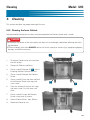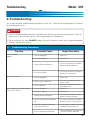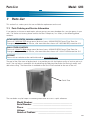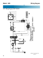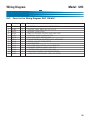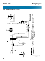
1
Operations & Service Manual
GHC
Model: GHC
Giles Enterprises, Inc.
FOODSERVICE EQUIPMENT
An ISO9001 Registered Company
2750 Gunter Park Drive West • Montgomery, AL 36109 USA
Phone: (334) 272-1457 Fax: • (334) 272-3561 • Internet: www.gilesent.com
Service Hotline (Toll Free): 1-800-554-4537 (USA & Canada Only)
Form No. 60359 (Release date: 3/01)(Revision Date: 7/20/04)(Revision Level: B)
LIMITED WARRANTY
•
Subject to the terms and conditions of this Limited Warranty as herein stated, all Giles Enterprises,
Inc., Foodservice Equipment and parts purchased new from an authorized Giles Enterprises, Inc.,
representative are warranted as to defects in material or workmanship for a period of 12 months
from the date of installation, provided, however, that with regard to labor costs in connection with
this warranty, see below. All installations must be made by a qualified installing agency in accordance with all applicable codes and/or regulations in the jurisdiction in which installed. Limited warranty coverage is extended to the original owner only and is void if the unit is resold.
•
During the Limited Warranty period, Giles Enterprises, Inc. will replace or recondition, at its factory,
any part or parts of this unit which Giles Enterprises, Inc. inspectors judge defective, provided the
unit has been subjected to normal usage, properly installed, operated and serviced. This Limited
Warranty does not cover cosmetic damage, and damage due to acts of God, accident, misuse, alteration, negligence, abuse of the Giles Foodservice Equipment or the use of unorthodox repair methods. All parts replaced under this Limited Warranty carry only the unexpired term of this Limited
Warranty. Limited Warranty service may be furnished only by an authorized Giles Enterprises, Inc.,
representative.
•
If Limited Warranty service is requested, Giles Enterprises, Inc., will send factory-authorized service representatives to repair, recondition, replace or inspect units of its manufacture with such labor
being rendered without cost to owner for ninety (90) days from the date of installation. Otherwise,
service, including labor and transportation charges or other expenses, in connection with the
removal or installation of any part or parts supplied under this Limited Warranty, are specified on the
original sales contract between the purchaser and the authorized Giles Enterprises, Inc., representative.
•
Giles Enterprises, Inc. reserves the right to change or improve its equipment and parts in any way
without obligation to alter such equipment or parts previously manufactured.
•
Giles Enterprises, Inc. makes no further warranties, express or implied including implied warranties
of merchantability or fitness for a particular purpose, and has no other obligation or liability not
specifically stated herein.
•
Repair or replacement as provided under this Limited Warranty is the exclusive remedy. Giles
Enterprises, Inc., shall not be liable for any incidental or consequential damages for breach of any
express or implied warranty on this product, except to the extent prohibited by applicable law. Any
implied warranty of merchantability or fitness for a particular purpose on this product is limited in
duration to the duration of this Limited Warranty.
•
Used Giles Enterprises, Inc., Foodservice Equipment or parts or Giles Enterprises, Inc., Foodservice
Equipment or parts not purchased from an authorized Giles Enterprises, Inc., representative, carry
no warranties, express or implied.
Table Of Contents
Safety
Model: GHC
........................................................v
Safety Overview . . . . . . . . . . . . . . . . . . . . . . . . . . . . . . . . . . . . . . . . . . . . . . . . . . . . . . . . . . . . . . . . . . . . v
Specific Safety Precautions . . . . . . . . . . . . . . . . . . . . . . . . . . . . . . . . . . . . . . . . . . . . . . . . . . . . . . . . . . . vi
1.
Introduction . . . . . . . . . . . . . . . . . . . . . . . . . . . . . . . . . . . . . . . . . . . . . . 1
1-1.
1-2.
1-3.
1-3.1.
1-3.2.
1-3.3.
Construction . . . . . . . . . . . . . . . . . . . . . . . . . . . . . . . . . . . . . . . . . . . . . . . . . . . . . . . . . . . . . . 1
Standard Features. . . . . . . . . . . . . . . . . . . . . . . . . . . . . . . . . . . . . . . . . . . . . . . . . . . . . . . . . . 1
Specifications . . . . . . . . . . . . . . . . . . . . . . . . . . . . . . . . . . . . . . . . . . . . . . . . . . . . . . . . . . . . . 2
Overall Dimensions for GHC . . . . . . . . . . . . . . . . . . . . . . . . . . . . . . . . . . . . . . . . . . . . . . . . . 2
Regulatory Listings . . . . . . . . . . . . . . . . . . . . . . . . . . . . . . . . . . . . . . . . . . . . . . . . . . . . . . . . . 3
Unit Weights . . . . . . . . . . . . . . . . . . . . . . . . . . . . . . . . . . . . . . . . . . . . . . . . . . . . . . . . . . . . . . 3
2.
Installation . . . . . . . . . . . . . . . . . . . . . . . . . . . . . . . . . . . . . . . . . . . . . . . 5
2-01.
2-02.
2-03.
2-04.
2-05.
2-05.1.
2-05.2.
2-05.3.
2-05.4.
Location . . . . . . . . . . . . . . . . . . . . . . . . . . . . . . . . . . . . . . . . . . . . . . . . . . . . . . . . . . . . . . . . . 5
Unpacking . . . . . . . . . . . . . . . . . . . . . . . . . . . . . . . . . . . . . . . . . . . . . . . . . . . . . . . . . . . . . . . . 6
Electrical Requirements . . . . . . . . . . . . . . . . . . . . . . . . . . . . . . . . . . . . . . . . . . . . . . . . . . . . . 7
Electrical Connections . . . . . . . . . . . . . . . . . . . . . . . . . . . . . . . . . . . . . . . . . . . . . . . . . . . . . . 7
Controller Setup . . . . . . . . . . . . . . . . . . . . . . . . . . . . . . . . . . . . . . . . . . . . . . . . . . . . . . . . . . . 8
Setting Controller to Fahrenheit or Celsius (Programming Mode) . . . . . . . . . . . . . . . . . . . . . 8
Program Temperature Range (Programming Mode) . . . . . . . . . . . . . . . . . . . . . . . . . . . . . . . . 9
Program Low Temperature Alarm Range (Programming Mode) . . . . . . . . . . . . . . . . . . . . . . 10
Disable Low Temperature Alarm (Programming Mode) . . . . . . . . . . . . . . . . . . . . . . . . . . . . 11
3.
Overview . . . . . . . . . . . . . . . . . . . . . . . . . . . . . . . . . . . . . . . . . . . . . . . 13
3-01.
3-02.
3-03.
Control Panel. . . . . . . . . . . . . . . . . . . . . . . . . . . . . . . . . . . . . . . . . . . . . . . . . . . . . . . . . . . . . 14
Inner Cabinet . . . . . . . . . . . . . . . . . . . . . . . . . . . . . . . . . . . . . . . . . . . . . . . . . . . . . . . . . . . . 16
Accessories (Included) . . . . . . . . . . . . . . . . . . . . . . . . . . . . . . . . . . . . . . . . . . . . . . . . . . . . . 18
4.
Operation . . . . . . . . . . . . . . . . . . . . . . . . . . . . . . . . . . . . . . . . . . . . . . . 19
4-01.
4-02.
4-03.
4-04.
4-05.
4-06.
Setting the Temperature (Normal Operation Mode) . . . . . . . . . . . . . . . . . . . . . . . . . . . . . . . 19
Setting the Low Temperature Alarm (Normal Operation Mode) . . . . . . . . . . . . . . . . . . . . . . 19
Silence the Low Temperature Alarm (Normal Operation Mode). . . . . . . . . . . . . . . . . . . . . . 20
Operating the unit. . . . . . . . . . . . . . . . . . . . . . . . . . . . . . . . . . . . . . . . . . . . . . . . . . . . . . . . . 20
Normal Shut-Down . . . . . . . . . . . . . . . . . . . . . . . . . . . . . . . . . . . . . . . . . . . . . . . . . . . . . . . . 21
Emergency Shut-Down. . . . . . . . . . . . . . . . . . . . . . . . . . . . . . . . . . . . . . . . . . . . . . . . . . . . . 21
5.
Cleaning . . . . . . . . . . . . . . . . . . . . . . . . . . . . . . . . . . . . . . . . . . . . . . . . 23
5-01.
Cleaning the Inner Cabinet . . . . . . . . . . . . . . . . . . . . . . . . . . . . . . . . . . . . . . . . . . . . . . . . . . 23
6.
Troubleshooting . . . . . . . . . . . . . . . . . . . . . . . . . . . . . . . . . . . . . . . . . 25
6-1.
Troubleshooting Procedures . . . . . . . . . . . . . . . . . . . . . . . . . . . . . . . . . . . . . . . . . . . . . . . . . 25
iii
Model: GHC
Table Of Contents
7.
Parts List . . . . . . . . . . . . . . . . . . . . . . . . . . . . . . . . . . . . . . . . . . . . . . . 27
7–1.
7-2.
7-3.
Parts Ordering and Service Information . . . . . . . . . . . . . . . . . . . . . . . . . . . . . . . . . . . . . . . . 27
Front and Upper Components . . . . . . . . . . . . . . . . . . . . . . . . . . . . . . . . . . . . . . . . . . . . . . . 28
Inner Cabinet Components. . . . . . . . . . . . . . . . . . . . . . . . . . . . . . . . . . . . . . . . . . . . . . . . . . 30
8.
Wiring Diagram . . . . . . . . . . . . . . . . . . . . . . . . . . . . . . . . . . . . . . . . . . 33
8-01.
8-02.
Wiring Diagram GHC 120/60/1 . . . . . . . . . . . . . . . . . . . . . . . . . . . . . . . . . . . . . . . . . . . . . . . 34
Wiring Diagram GHC 230/50/1 . . . . . . . . . . . . . . . . . . . . . . . . . . . . . . . . . . . . . . . . . . . . . . . 36
iv
Safety
Model: GHC
Safety
Safety Overview
The instructions contained in this manual have been prepared to assist you in learning the proper procedures for installing and servicing your unit.
Throughout this manual, safety precautions are identified through the use of the safety alert symbol and
three signal words: DANGER, WARNING, and CAUTION. All safety alert information precedes the
step(s) to which they apply. Suggested, recommended, or other noteworthy information is identified
through the use of NOTES. Additionally, certain words are used to indicate a specific meaning or to add
emphasis.
The following words are used as indicated throughout the manual:
Shall: understood to be mandatory.
Should: understood to be advisory.
May: understood to be permissive.
Will: indicates a future event/condition to occur.
! or !
(Safety Alert Symbol)
Used in conjunction with signal words (DANGER, WARNING, or CAUTION) to alert you of potential personal injury hazards, immediately preceding precautionary measures that pertain to subsequent step(s).
Obey all safety messages that follow this symbol to avoid possible injury or death. Failure to adhere to
safety precautions identified by the safety alert symbol may also void the warranty.
!
DANGER
• Indicates an imminently hazardous situation which, if not avoided, will result in death or serious injury.
Use of this is limited to the most extreme situations.
! WARNING
• Indicates a potentially hazardous situation which, if not avoided, could result in death or serious injury.
! CAUTION
• Indicates a potentially hazardous situation which, if not avoided, may result in minor or moderate injury.
Also used to alert against unsafe practices.
CAUTION
• When used without the safety alert symbol, CAUTION indicates a potentially hazardous situation
which, if not avoided, may result in equipment/property damage, and void the warranty.
NOTE:
• Identifies suggested, recommended, or other noteworthy information.
v
Model: GHC
Safety
Specific Safety Precautions
For your safety, please observe the following precautions when operating or servicing your Giles Holding
Cabinet (GHC). Read the following important safety information to avoid personal injury and/or damage to
the equipment.
!
DANGER
• Always disconnect the source of the main power before removing the Cabinet Top.
• Always disconnect the source of the main power before removing the Element Guard.
• Failure to comply with these DANGER notices will result in death or serious injury, equipment/property
damage, and void the warranty.
! WARNING
• DO NOT use or store gasoline or other flammable liquids or vapors in the vicinity of this or any other
appliance!
• Consult a qualified electrician to ensure all electrical specifications have been met and the unit is properly grounded.
• Before installing or servicing this equipment, read the contents of this manual thoroughly.
• Improper installation, adjustment, alteration, service or maintenance could result in death or serious
injury, equipment/property damage, and void the warranty.
• Failure to comply with these WARNING notices could result in death or serious injury and
equipment/property damage.
CAUTION
• The electronic components of the Control Panel are impact-sensitive.
Exercise care around the Control
Panel to maintain proper operation.
• During cleaning of unit.
•• DO NOT steam clean.
•• DO NOT use products containing chlorine.
•• DO NOT use abrasive products, steel wool or scouring pads.
• Failure to comply with these CAUTION notices may result in equipment/property damage and void the
warranty.
vi
Safety
Model: GHC
! CAUTION
• Exercise care when lifting or moving the unit. See Section 1-3.3. for unit weights.
• Exercise care when removing the wooden shipping crate from around the unit.
NOTE:
• If the shipping crate is damaged, immediately inspect the unit and notify the carrier of any damage to
the unit.
• To aid the electrician an electrical wiring diagram is contained in this manual.
Refer to the wiring dia-
gram during installation or servicing.
• Comply with all appropriate state and/or local heath regulations regarding the cleaning and sanitation of
equipment.
• For difficult areas, a mild biodegradable nontoxic degreaser (such as Clear Magic or Simple Green) may
be used.
• Please ensure this appliance is electrically grounded and installed in accordance with local codes, or in
the absence of local codes, with the National Electrical Code ANSI/NFPA No. 70-1984.
vii
Model: GHC
Notes:
viii
Safety
Introduction
1.
Model: GHC
Introduction
Congratulations on the purchase of your new Giles Holding Cabinet, Model GHC, manufactured by Giles
Enterprises, Inc., Montgomery, Alabama (USA), hereafter referred to as "Giles". The Holding Cabinet is a
product of extensive research and testing, designed to hold prepared foods for prolonged periods of time
while maintaining that “just made” quality. Every unit is thoroughly inspected and tested prior to shipment. Proper care and maintenance will ensure years of trouble-free service.
Ideal for cafeterias, deli’s, convenience stores, supermarkets or any store that must conserve valuable
space. The materials used were selected for maximum durability, attractive appearance and optimum performance. The use of controlled heat maintains serving temperature and texture longer than conventional
holding equipment.
To help protect your investment in this equipment, we recommend taking a few moments to familiarize
yourself with the installation, cleaning and maintenance procedures contained in this manual. Read these
instructions before installation and use. Adherence to these recommended procedures minimizes the
potential for costly "down-time" and equipment repairs. Please retain this manual for future reference.
1-1. Construction
The Holding Cabinet, Model GHC, is constructed of stainless steel, with stainless steel work surfaces. It
has two nickel plated vertical product racks and six horizontal product racks that can be organized in many
variations. The Holding Cabinet features individual thermostatic controlled heating environment, two firebar heating elements, hot air circulating fan, and four 4" casters.
1-2. Standard Features
Control Panel
• Controls are functional, easy to operate.
• Indicator lights verify the unit is operating and that the heating elements are operating.
Temperature Controls
• Adjustable control up to 210ºF (98.9ºC).
Front Doors
• Stainless steel construction, insulated with 1" thick ceramic insulation.
• French style doors for full access and to save door opening space.
1
Model: GHC
1-3. Specifications
1-3.1. Overall Dimensions for GHC
2
Introduction
Introduction
Model: GHC
1-3.2. Regulatory Listings
UL (US and Canada)
NSF
1-3.3. Unit Weights
Unit
Crated Weight
Uncrated Weight
(without product or pans)
GHC
336 lbs [152.4 kg]
216 lbs [97.97 kg]
3
Model: GHC
Notes:
4
Introduction
Installation
Model: GHC
2. Installation
This section provides a summary of procedures necessary to install your new Giles Holding Cabinet,
Model GHC. Before installing or servicing this equipment, please read the contents of this manual
thoroughly. Following these procedures ensures a safe and proper installation.
2-01. Location
CAUTION
• DO NOT install the unit next to combustible walls and materials.
Failure to maintain safe distances may result in
combustion.
• DO NOT MODIFY, ALTER OR ADD ATTACHMENTS TO THIS EQUIPMENT.
• Failure to comply with these CAUTION notices may result in minor or moderate injury, equipment/property damage, and void the warranty.
1. Select a location with adequate space to properly operate and service the GHC.
2. Maintain a minimum clear distance of 1 inch (25.4 mm) between wall and unit to allow for adequate
ventilation.
3. Ensure the installation area is free of combustible materials.
4. Ensure the Specific Requirements contained in paragraph 2-02 are adhered to in determining location.
5
Model: GHC
Installation
2-02. Unpacking
Your unit should arrive packaged in a wooden crate, covered with plastic shipping wrap, and secured to a
wooden platform by means of high-tensile strength strapping. Perform the following steps to uncrate the
unit:
NOTE:
• If the crate is damaged, immediately inspect the unit and notify the carrier of any damage to the unit.
! CAUTION
•
Exercise care when lifting or moving the unit, please see Section 1-3.3 for unit weights.
•
Exercise care when removing the wooden crate from around the unit.
•
Failure to comply with these CAUTION notices may result in minor or moderate injury,
equipment/property damage, and void the warranty.
1. Position the packaged GHC in an area with sufficient room for unpacking.
2. Cut and remove the plastic shipping wrap and any high-tensile strength straps from the exterior of the
wooden crate.
3. Carefully use a hammer and pry bar to remove the wooden crate from around the unit.
4. Cut and remove the plastic shipping wrap and high-tensile strength strapping that secures the unit to
the wooden platform.
5. Before installing, check the unit for damage. If unit was damaged during shipment, notify the carrier
immediately and file a claim.
6. Carefully remove the unit from the wooden platform and place at the installation site.
7.
6
Lock Casters when unit is installed in it’s final installation site.
Installation
Model: GHC
2-03. Electrical Requirements
! WARNING
•
Consult a qualified electrician to ensure all electrical specifications have been met and the unit is properly
grounded.
•
Improper installation, adjustment, alteration, service or maintenance could result in death or serious injury, equipment/property damage, and void the warranty.
Electrical Requirements
Unit
Voltage
Hz
Phase
Watts
Amps
Breaker
GHC
120
60
1
1350
11.3
20
GHC
230
50
1
1350
5.9
10
120V Unit is shipped with a 84” [2133.6mm] service cord and plug.
120V Plug Type- NEMA Configuration 5-15P
230V Unit is shipped with a 84” [2133.6mm] service cord only. Plug is to be supplied by customer.
2-04. Electrical Connections
! WARNING
•
The GHC must be properly grounded and all electrical specifications must be met during installation.
•
Improper installation, adjustment, alteration, service or maintenance could result in death or serious injury, equipment/property damage, and void the warranty.
1. Ensure the power switch on the Control Panel is in the OFF position.
2. Plug the Power Cord into the dedicated facility electrical receptacle (20 Amp minimum).
7
Model: GHC
Installation
2-05. Controller Setup
2-05.1.
Setting Controller to Fahrenheit or Celsius (Programming Mode)
The following procedure explains how to place the contoller in the programming mode and set the temperature to display in Fahrenheit or Celsius.
Step 2
Step 1
Power
Off
Step 3
While Pressing and
Holding both Up
and Down Arrows,
press Power On
Display reads,
until buttons are
released
+
Step 4
Press
or
8
Step 6
Step 5
Display reads
or
Power
Off
Installation
2-05.2.
Model: GHC
Program Temperature Range (Programming Mode)
The following procedure explains how place the contoller in the programming mode and program the temperature adjustment range (lowest to highest temperatures) used during normal operation of the unit.
Step 1
Power
Off
Step 2
Step 3
While Pressing and
Holding both Up
and Down Arrows,
press Power On
Display reads
Step 4
Press
+
Step 5
Display reads
(Lowest
Temperature)
Step 6
Step 7
Press to
Adjust
Display
reads
Step 8
Press
or
Step 9
Display reads
(Highest
Temperature)
Step 10
Press to
Adjust
Step 11
Display
reads
Step 12
Power
Off
or
9
Model: GHC
2-05.3.
Installation
Program Low Temperature Alarm Range (Programming Mode)
The following procedure explains how to place the contoller in the programming mode and program the
alarm adjustment range (lowest to highest points) for use during normal operation of the unit.
Step 1
Power
Off
Step 2
Step 3
While Pressing and
Holding both Up
and Down Arrows,
press Power On
Display reads
Step 4
Press
+
Step 5
Display reads
(Low Alarm
Temperature)
Step 6
Step 7
Press to
Adjust
Display
reads
Step 8
Press
or
Step 9
Display reads
(High Alarm
Temperature)
Step 10
Press to
Adjust
or
10
Step 11
Display
reads
Step 12
Power
Off
Installation
2-05.4.
Model: GHC
Disable Low Temperature Alarm (Programming Mode)
The following procedure explains how to place the controller in the programming mode and disable the
Low Temperature Alarm
Step 1
Power
Off
Step 2
While Pressing and
Holding both Up
and Down Arrows,
press Power On
Step 3
Display reads
Step 4
Press
+
Step 5
Display reads
(Low Alarm
Temperature)
Step 6
Press and hold
until display
reads “OFF”
Step 7
Display
reads
Step 8
Power
Off
11
Model: GHC
Notes:
12
Installation
Overview
Model: GHC
3. Overview
The following section provides a brief overview of the components, functions, and accessories of the
GHC. Please review this section carefully before proceeding any further.
Control Panel
See Section 3-01
Door
Inner Cabinet
Door
13
Model: GHC
Overview
3-01. Control Panel
3
2
5
6
14
4
1
Overview
Model: GHC
3-01. Control Panel
Item
Description
Function
1
Power Switch
The Power Switch is a two-position Switch. Move the switch
upward to the “ON” position for operation.
2
Display
3
Alarm Reset
4
Up and Down Arrows
5
Heat Light
Used to indicate that the heating elements are on.
6
Temp Set
Used for setting the inner cabinet temperature and other
various options.
Used to display the actual inner temperature of unit, the
temperature settings, and various messages.
Used to program and silence the Low Temperature Alarm.
Use to scroll settings higher or lower.
15
Model: GHC
Overview
3-02. Inner Cabinet
2
1
16
1
3
Overview
Model: GHC
3-02. Inner Cabinet
Item
Description
Function
1
Vertical Rack
Used to support the shelves and allows the shelves to be
adjusted.
2
Product Shelf
(6 included)
Used to store cooked product in the unit.
3
Circulation Fan
Used to circulate hot air through the inner cabinet for quick and
even heating inside the unit.
17
Model: GHC
3-03.
Accessories (Included)
Part
18
Overview
Description/Part Number
Function
Product Shelf
(6 included)
P/N 36279
Support Product placed in unit
Shelf Support Rack
(2 included)
P/N 36278
Support Product Shelves
Operation
Model: GHC
4. Operation
This section describes how to operate the unit.
4-01. Setting the Temperature (Normal Operation Mode)
This section describes how to set the temperature of the GHC in the Normal Operation Mode. Your unit is
shipped programmed with an allowable temperature range from 140 F to 150 F. If you need a higher or
lower range please see Section 2-05.2., Programming the Temperature Range (Programming Mode).
Step 2
Step 1
Power
On
Step 3
Press and Hold Temp
Set and adjust with
up or down
+
Display reads
temperature
setting
or
4-02. Setting the Low Temperature Alarm (Normal Operation Mode)
This section describes how to set the Low Temperature Alarm in the Normal Operation Mode. If this alarm
is enabled, the unit will sound an alarm if the temperature inside the cabinet drops below the Low
Temperature Alarm set point. The unit is shipped with this option disabled. To enable and set this option
please see Section 2-05.3. Programming the Low Temperature Range (Programming Mode).
Step 1
Power
On
Step 2
Step 3
Press and Hold Alarm
Reset and adjust with
up or down
+
Display reads
temperature
setting
or
19
Model: GHC
Operation
4-03. Silencing the Low Temperature Alarm (Normal Operation Mode)
(If the Low Temperature Alarm feature is enabled)
If during normal operation of the unit the temperature drops below the Low Temperature Alarm setting, an alarm will sound. You may press the Alarm Reset Button to silence the alarm. The alarm will
also silence once the unit’s inside cabinet temperature exceeds the Low Temperature setting.
Note: If you press the Alarm Reset Button to silence the alarm, the alarm will not sound again regardless of the temperature of the unit for 20 minutes.
Press
4-04. Operating the unit
This section describes the basic operation of the unit.
3
2
1
5
4
1. Press the Power Switch to the ON 1 position. The Display 2 will toggle between the word “Lo” (if
the Low Temperature Alarm feature is enabled) and the current temperature inside the cabinet. The
Heat Light 3 will come on and the unit will begin heating.
2. To check the current set temperature press the Temp Set 4 button. The Display will show the current set temperature for 20 seconds, then the Display will return toggling between the word “Lo” and
the current temperature inside the cabinet.
3. (If the Low Temperature Alarm feature is enabled) To check the current set Low Temperature Alarm
press the Alarm Reset 5 button. The Display will show the current set Low Temperature Alarm for
20 seconds, then the Display will return toggling between the word “Lo” and the current temperature
inside the cabinet.
Note: If the Low Temperature Alarm feature is disabled, when the Alarm Reset button is pushed the
Display will read “OFF.”
(Continued next page)
20
Operation
Model: GHC
4. Allow the unit to preheat for approximately 30 minutes.
5. Once the unit has preheated, the Heat Light 3 will go out and the display will no longer toggle the
word “Lo” (if the Low Temperature Alarm feature is enabled) and will continously show the temperature of the inside of the cabinet.
6. You may now place the cooked product in the unit.
7.
Using a Food Thermometer, periodically check to determine that the temperature of the food products
on each shelf inside the GHC is being maintained at 150°F (65.5°C) or such other minimum temperature as may be established by local and state health regulations.
8. (If the Low Temperature Alarm feature is enabled)
If during normal operation of the unit the temperature inside the cabinet drops below the Low
Temperature Alarm setting, an alarm will sound. You may press the Alarm Reset Button 5 to silence
the alarm. The alarm will silence once the unit’s inside temperature exceeds the Low Temperature setting.
Note: If you press the Alarm Reset Button 5 to silence the alarm, the alarm will not sound again for
20 minutes, regardless of the temperature inside the unit.
4-05. Normal Shut-Down
1
1. Press the Power Switch to the OFF 1 position.
4-06. Emergency Shut-Down
In case of emergency, remove power to the unit by turning off the facility circuit breaker.
21
Model: GHC
Notes:
22
Operation
Cleaning
Model: GHC
5. Cleaning
This section describes the proper cleaning of the unit.
5-01. Cleaning the Inner Cabinet
We recommend cleaning the unit daily and cleaning behind the Element Guard once a month.
!
DANGER
• Disconnect the source of the main power and allow unit to thoroughly cool before following the cleaning procedure.
• Failure to comply with these DANGER notices will result in death or serious injury, equipment/property
damage, and void the warranty.
1
1.
Disconnect Power to the unit and allow
the unit to cool.
2.
Remove all Shelves and Racks.
3.
(Once a month) Remove (4) 1 screws
fastening Element Guard to the unit.
4.
(Once a month) Remove the Element
Guard.
5.
(Once a month) Clean the front and back
of the Element Guard with soap and
warm water.
6.
Clean the interior of the unit with soap
and warm water. Dry with clean soft
cloth.
7.
(Once a month) Fasten the Element
Guard, using same (4) screws.
8.
Reinstall Vertical Racks, then Shelves.
9.
Reconnect Power to unit.
1
1
1
23
Model: GHC
Notes:
24
Cleaning
Troubleshooting
Model: GHC
6.Troubleshooting
This section describes troubleshooting procedures for the GHC. Refer to the wiring diagrams in Section 8
for more detailed analysis.
!
•
DANGER
Electrical troubleshooting procedures should be done ONLY by qualified service personnel. Death or
serious injury will result from contact with energized electrical components.
• Failure to comply with these DANGER notices will result in death or serious injury, equipment/property
damage, and void the warranty.
6-1. Troubleshooting Procedures
Problem
Unit not heating
properly.
Unit will not turn on.
Unit will not maintain food temperature of 150ºF (65.5°C).
Probable Cause
Repair Procedure
a. Unit not plugged in.
a. Plug unit in.
b. Unit not turned on.
b. Turn unit on.
c. Heating Element defective.
c. Call service technician to replace
defective Heating Element.
d. Fan not circulating.
d. Call service technician to replace
defective Circulating Fan.
a. Unit not plugged in.
a. Plug in Unit.
b. Power switch is defective.
b. Call service technician to check
Power switch.
c. Fuse is defective.
c. Unplug unit from power source
and replace fuse.
a. Unit not plugged in.
a. Plug unit in.
b. Unit not turned on.
b. Turn unit on.
c. Heating Element defective.
c. Call service technician to replace
defective Heating Element.
d. Hot Air Circulating fan not operating.
d. Call service technician to replace
defective Hot Air Circulating Fan.
e. Food not at proper temperature
when placed into unit.
e. Insure food is at required temperature before placing into unit.
f. Unit isn’t programmed correctly
f. Refer to programming instructions
in Section 2 and 4 Operation
25
Model: GHC
Notes:
26
Troubleshooting
Parts List
7.
Model: GHC
Parts List
This section lists various parts that are available for replacement on the unit.
7–1. Parts Ordering and Service Information
If you require assistance or need repairs, please contact your area developer for a service agency in your
area. For further assistance, please contact the Giles Enterprises, Inc. factory at the following phone
numbers:
IN THE UNITED STATES, CANADA or MEXICO
Please call 1-800-288-1555 during normal business hours, 8:00AM-5:00PM Central Time Zone; for
Emergency Equipment Repair Service, after normal business hours call 1-800-288-1555, extension 314.
IN ALL OTHER COUNTRIES
Please call 1-334-272-3528 during normal business hours, 8:00AM-5:00PM Central Time Zone; for
Emergency Equipment Repair Service, after normal business hours call 1-334-272-3528 extension 314.
INTERNET
Please visit our website on the world wide web at: www.gilesent.com.
The goal of the Giles team of professionals is to provide you with the highest quality of service and assistance. You can help us accomplish this by obtaining the following information and having it readily available when calling. The information is recorded on the Serial Plate attached to the rear of the unit.
Serial Plate
The area below may be helpful in recording information for use as a quick reference.
Model Number: ______________________________________
Serial Number: ______________________________________
Phase:
___________________________________________
Voltage: ___________________________________________
Nature of Problem: _________________________________
27
Model: GHC
Parts List
7-2. Front and Upper Components
5
10
6
9
7
4*
3
*2
* -Not shown
28
1
8
Parts List
Model: GHC
7-2. Parts List for Front and Upper Components
Item
1
2
3
4
5
6
7
8
9
10
Part No.
60246
21190
20026
37068
37616
20169
20170
23751
21950
21900
Qty.
1
1
1
1
1
1
1
1
1
1
Description
LABEL, CONTROL PANEL, WARMING CABINET
SWITCH, ROCKER, ON-OFF, 250V, 20A, DPST
CONTROLLER,0-210 DEG F. NCC, GHC
COVER, CABINET TOP, WELDMENT
TRANSFORMER & ADAPTER PLATE, ASSY,60HZ
RELAY,SSR,240V OUTPUT,24VAC INPUT,25A
HEAT SINK,SSR
TERMINAL BLOCK, MA106,6 POLE
HOLDER, FUSE, 300V, 15A, SC 0 TO 15
FUSE, 15AMP, SC-15
* -Not shown
29
Model: GHC
Parts List
7-3. Inner Cabinet Components
9
10
9
8
8
6
7
1
6
7
2
4*
5*
* -Not shown
30
3
Parts List
Model: GHC
7-3. Parts List for Inner Cabinet Components
Item
1
2
3
4*
5*
6
7
8
9
9
10
10
Part No.
36443
36442
40271
36257
21803
36208
36631
40270
20027
20195
20035
20194
Qty.
1
1
4
1
1
2
4
2
2
2
1
1
Description
RIGHT DOOR, ASSY. (INCLUDES HANDLE, HINGE AND GASKET)
LEFT DOOR, ASSY. (INCLUDES HANDLE, HINGE AND GASKET)
HINGE, EDGEMOUNT
GUARD, FAN & ELEMENT
GUARD, FAN
GASKET, LONG EXTRUSION DOOR
GASKET,SHORT EXTRUSION DOOR
HANDLE, MAGNETIC STRIKE
ELEMENT, 650W, 120V, GHC
ELEMENT, 650W, 240V, GHC
FAN, 120V, 60HZ, 110CFM, GHC
FAN, 230V, 50HZ, 110CFM, GHC
* -Not shown
31
Model: GHC
32
Parts List
Wiring Diagram
Model: GHC
8. Wiring Diagram
The following section contains various Wiring Diagrams for the GHC units. Please check the Serial Plate,
as shown below, for the unit’s Model Name, Voltage, Hertz, and Phase.
Serial Plate
33
Model: GHC
Wiring Diagram
8-01. Wiring Diagram GHC 120/60/1
WIRING DIAGRAM P/N:
36316-E
34
Wiring Diagram
Model: GHC
8-01. Parts List for Wiring Diagram GHC 120/60/1
Item
1
2
3
4
5
6
7
8
9
10
11
12
13
14
Part No.
20080
21950
25275
21190
23751
20035
37616
20038
20170
20169
20027
20026
38365
20500
Qty.
1
1
7
1
1
1
1
1
1
1
2
1
1
1
Description
CORDSET,GHC,120VAC,16/3 CORD W/PLUG
HOLDER, FUSE, 300V, 15A, SC 0 TO 15
WIRENUT, IDEAL BLUE
SWITCH, ROCKER, ON-OFF, 250V, 20A, DPST
TERMINAL BLOCK, MA106,6 POLE
FAN, 120V, 60HZ, 110CFM, GHC
TRANSFORMER & ADAPTER PLATE, ASSY,60HZ
PROBE, 3.00 NTC THERMISTOR
HEAT SINK,SSR
RELAY,SSR,240V OUTPUT,24VAC INPUT,25A
ELEMENT, FIREBAR, 650W, 120V, GHC
CONTROLLER,0-210 DEG F. NCC, GHC
ASSY,FUSE,CONTROLLER TRANSFORMER
CAPACITOR, QUENCHARC, 250V, 120 OHMS
35
Model: GHC
Wiring Diagram
8-02. Wiring Diagram GHC 230/50/1
WIRING DIAGRAM P/N:
38177-C
36
Wiring Diagram
Model: GHC
8-02. Parts List for Wiring Diagram GHC 230/50/1
Item
1
2
3
4
5
6
7
8
9
10
11
12
13
Part No.
20177
21950
25275
21190
23751
20194
37770
20038
20170
20169
20195
20026
20500
Qty.
1
1
9
1
1
1
1
1
1
1
2
1
1
Description
WIRE,3X4.00mm,CE,3 WIRE RUBBER CABLE,
HOLDER, FUSE, 300V, 15A, SC 0 TO 15
WIRENUT, IDEAL BLUE
SWITCH, ROCKER, ON-OFF, 250V, 20A, DPST
TERMINAL BLOCK, MA106,6 POLE
FAN, 230V, 50HZ, 110CFM, GHC
TRANSFORMER & ADAPTER PLATE, ASSY,50HZ_
PROBE, 3.00 NTC THERMISTOR
HEAT SINK,SSR
RELAY,SSR,240V OUTPUT,24VAC INPUT,25A
ELEMENT, FIREBAR HEATING, 240V 650W
CONTROLLER,0-210 DEG F. NCC, GHC
CAPACITOR, QUENCHARC, 250V, 120 OHMS
37
Model: GHC
Notes:
38
Wiring Diagram
FOODSERVICE EQUIPMENT
Giles Enterprises, Inc.
2750 Gunter Park Drive West • Montgomery, Al 36109 USA
(334) 272-1457 • Service Hotline 1-800-554-4537 (USA & Canada Only) • FAX (334) 272-3561 • www.gilesent.com
Form No. 60359 (Release date: 03/01)(Revision Date: 07/20/04)(Rev B)(ECO0858)(CSY)