1
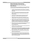
96-104260 Rev. 2.0
Thermocouple Calibration
Thermocouple Calibration
Thermocouple Calibration for Software up to and
including Rev. 3.00
Incorrect or inaccurate calibration may cause unsuccessful
sterilization of instruments.
Always calibrate the thermocouples after a thermocouple
replacement, thermocouple bend or disconnect, controller board
replacement or microprocessor / EEPROM replacement, steam
generator replacement or probe bracket replacement.
Make sure that there is sufficient steam-process distilled water in
the unit prior to starting calibration.
Do not place the digital reference thermometer in direct sunlight,
on the armature or on any other hot surfaces. This may cause
improper values on the temperature readout.
STATIM Cassette Autoclaves have been manufactured using different
Controller Boards. See Controller Board Hardware / Software,
Identifying the Controller Board Type. Assembly and revision numbers
are located on the bottom right-hand portion of the component side of
the board. For detailed differences between board versions, see
Controller Board Hardware / Software.
Units containing boards bearing the following numbers must follow
Calibration Procedure for Type A Controller Board:
01-100005A, Version 3X
01-100004A, Version 3X
01-100004A, Version 4X
01-100020A, Version 3X
01-100638A, Version 3X
01-100992, Version 4X
01-101170, Version 4X
01-101172, Version 4X
1
STATIM Cassette Autoclave Service Manual
CONFIDENTIAL
Thermocouple Calibration
96-104260 Rev. 2.0
Thermocouple Calibration
Typically, these boards were manufactured with four potentiometers
(VREF, DISP, TC-CHM and TC-BLR) and do not have a printer connector.
Refer to these boards as Type A Controller Board.
Units containing boards bearing the following numbers must follow
Calibration Procedure for Type B Controller Boards:
01-101359, Any version, Type B
01-100881, Any version, Type B
01-101356, Any version, Type B
Units containing boards with the following numbers follow Calibration
Procedure for Software Rev. 4.00 and up.
01-108191Z, Any version, Type C
01-108380Z, Any version, Type C
01-108382Z, Any version, Type C
For other Controller Boards, contact SciCan.
Typically, these boards were manufactured with 3 potentiometers (VREF,
DISP and TC-ADJ), a six position J4 connector terminal labelled FLOAT
PROBE CASSIN and the P2 printer connector. Refer to these boards as
Type B and Type C Controller Boards.
2
STATIM Cassette Autoclave Service Manual
CONFIDENTIAL
96-104260 Rev. 2.0
Thermocouple Calibration
Thermocouple Calibration
Type A
4
9
1.
2.
3.
4.
5.
6.
7.
8.
9.
10.
10
Control Box
Controller Board
SELECT knob
VRH potentiometer
digital voltmeter
calibration cassette
thermocouple
digital thermometer
TC-CHM potentiometer
TC-BLR potentiometer
Figure 1
6
7
8
2
3
1
5
3
STATIM Cassette Autoclave Service Manual
CONFIDENTIAL
Thermocouple Calibration
96-104260 Rev. 2.0
Thermocouple Calibration
When referring to the Troubleshooting portion of this service manual,
note that there are specific check cassette error messages for Type A
Controller Boards, and specific cycle fault messages for Type B
Controller Boards.
For calibration equipment hookup and identification see Figure 1.
Calibration Procedure for Type A Controller Boards
These steps MUST be performed in sequence to calibrate a unit with a
Type A Controller Board:
1.
Reference Voltage Verification / Adjustment
2.
Steam Generator Thermocouple Calibration
3.
Chamber Thermocouple Calibration, including Steam Generator
recalibration.
Reference Voltage Verification / Adjustment
(Type A Boards)
To verify / adjust the reference voltage, follow these steps (see Figure 1):
1.
Turn the autoclave unit OFF, connect the Control Box (1) to the
Controller Board (2). Connect the digital voltmeter (5) to the VREF
terminals. Set the meter to read DC Volts with a resolution of 1mV.
2.
Power the autoclave unit ON.
3.
Adjust the VRH potentiometer until VREF is 4.000 V ± 0.001
4.
Once VREF is adjusted, apply a drop of non-conducting laquer or
nail polish to the adjustment screw of the potentiometer.
Steam Generator Thermocouple Calibration
(Type A Boards)
To calibrate the steam generator thermocouple, follow these steps
(see Figure 1):
1.
Turn the Control Box SELECT knob to blr-chm. This signal is
the difference between the chamber and steam generator
thermocouples. See, Required Information and Tools,
The Control Box.
4
STATIM Cassette Autoclave Service Manual
CONFIDENTIAL
96-104260 Rev. 2.0
Thermocouple Calibration
Thermocouple Calibration
2.
Set the meter (5) to read DC Volts with a resolution of 1 mV and
locate the TC-BLR (10) potentiometer on the Controller Board.
3.
Select the UNWRAPPED INSTRUMENT CYCLE button on the
Control Box, then press START. Follow the phases of the cycle as
they are displayed on the LCD (warming up, purging air,
pressurization, sterilization). Calibration occurs during the
sterilization phase.
4.
With 2 minutes and 25 seconds left in the sterilization cycle adjust
the TC-BLR potentiometer until the voltmeter reads 0.000 V ±
0.030 V.
Chamber Calibration Conversion - Chart A
TCHM
(˚C)
VCHMXGAIN
(VOLTS)
TCHM
(˚C)
VCHMXGAIN
(VOLTS)
TCHM
(˚C)
VCHMXGAIN
(VOLTS)
TCHM
(˚C)
VCHMXGAIN
(VOLTS)
134.0
134.1
134.2
134.3
134.4
134.5
134.6
134.7
134.8
134.9
135.0
135.1
135.2
2.259
2.262
2.265
2.268
2.271
2.274
2.278
2.281
2.284
2.287
2.290
2.293
2.296
135.3
135.4
135.5
135.6
135.7
135.8
135.9
136.0
136.1
136.2
136.3
136.4
136.5
2.300
2.303
2.306
2.309
2.312
2.315
2.318
2.322
2.325
2.328
2.331
2.334
2.337
136.6
136.7
136.8
136.9
137.0
137.1
137.2
137.3
137.4
137.5
137.6
137.7
137.8
2.340
2.343
2.347
2.350
2.353
2.356
2.359
2.362
2.365
2.369
2.372
2.375
2.378
137.9
138.0
138.1
138.2
138.3
138.4
138.5
138.6
138.7
138.8
138.9
139.0
2.381
2.384
2.387
2.391
2.394
2.397
2.400
2.403
2.406
2.409
2.413
2.416
5
STATIM Cassette Autoclave Service Manual
CONFIDENTIAL
Thermocouple Calibration
96-104260 Rev. 2.0
Thermocouple Calibration
Chamber Thermocouple Calibration (Type A Boards)
There are no quick ways to calibrate a unit. Calibration requires a
number of readings and adjustments to achieve the required values.
Wait for equipment readings to stabilize and record them as quickly
and precisely as possible.
To calibrate the cassette thermocouple, follow these steps
(see Figure 1):
1.
Install the thermocouple (7) into the calibration cassette (6) and
attach the digital thermometer (8). Ensure that the thermocouple
and digital thermometer have matched serial numbers.
2.
Turn the Control Box (1) SELECT knob (3) to chm X gain. See,
Required Information and Tools, The Control Box. Locate the
TCCHM potentiometer (9) on the Controller Board (2).
3.
Set the meter (5) to read DC Volts with a resolution of 1 mV.
4.
Select the WRAPPED INSTRUMENT CYCLE button on the Control
Box, then press START. Follow the phases of the cycle as they are
displayed on the LCD (warming up, purging air, pressurization,
sterilization). Calibration occurs during the sterilization phase.
5.
After approximately 2 minutes into the sterilization phase look for
the digital thermometer (8) reading to remain constant for at least 2
seconds and record the values of the digital thermometer (TCHM)
and digital voltmeter (VM).
6
Using the TCHM value just recorded, find the corresponding
VCHMXGAIN value from the chamber calibration conversion chart.
See Chart A.
7.
Adjust the TCHM potentiometer until VM matches VCHMXGAIN for the
observed TCHM to within ± 0.005 V.
8.
Start another cycle and verify that the calibration readings are
within acceptable values. If not, repeat steps 4 through 7 until
acceptable values are achieved.
9.
Repeat the steam generator thermocouple calibration procedure.
6
STATIM Cassette Autoclave Service Manual
CONFIDENTIAL
96-104260 Rev. 2.0
Thermocouple Calibration
Thermocouple Calibration
10. Start another cycle and verify that the calibration readings are
within acceptable values. If the readings are not within these values
repeat step 9 until the proper voltmeter reading is obtained.
11. Once adjusted, apply a drop of non-conducting laquer or nail polish
to the adjustment screw of the TC-ADJ potentiometer.
Type B
10, 11
9
5
1.
2.
3.
4.
5.
6.
7.
8.
9.
10.
11.
Control Box
Controller Board
SELECT knob
digital voltmeter
Vref potentiometer
calibration cassette
thermocouple
digital thermometer
TC-ADJ potentiometer
Calibration jumper connection
Calibration jumper (not shown)
6
7
8
2
Figure 2
3
1
4
7
STATIM Cassette Autoclave Service Manual
CONFIDENTIAL
Thermocouple Calibration
96-104260 Rev. 2.0
Thermocouple Calibration
Calibration Procedure for Type B Controller Boards
The chamber and steam generator thermocouples must be calibrated to
ensure the correct operation of the STATIM. The steam generator
thermocouple is calibrated automatically by a special calibration cycle in
the Type B Controller Boards. The chamber thermocouple is calibrated
by adjusting a potentiometer on the Controller Board while comparing
the temperature on the LCD display with the temperature measured by
the digital reference thermometer within the calibration cassette.
In calibration mode no error messages are displayed. For calibration
equipment hookup and identification, observe these steps
(see Figure 2):
To calibrate a unit with a Type B Controller board, follow these steps
(see Figure 2):
1.
Before starting calibration, turn the STATIM OFF and remove the
cover. Check that there is sufficient steam process distilled water in
the reservoir, and that the calibration cassette (6) is correctly
engaged in the STATIM.
2.
Install the thermocouple (7) into the cassette and attach the digital
thermometer (8). Ensure that the thermocouple and digital
thermometer have matched serial numbers.
3.
Install the calibration jumper (11) to Controller Board pins
marked W1 (10).
4.
Adjust VREF. See Reference Voltage Verification and Adjustment
(Type B Boards).
5.
Calibrate the steam generator thermocouple. See Steam
Generator Thermocouple Calibration (Type B Boards).
6.
Calibrate the chamber thermocouple. See Chamber
Thermocouple Calibration (Type B Boards).
7.
Repeat step 5 and verify the chamber thermocouple calibration by
comparing the chamber temperature on the LCD with the reference
thermometer temperature.
8.
After calibration is complete, turn the STATIM OFF, remove the
calibration jumper and disconnect the Control box.
8
STATIM Cassette Autoclave Service Manual
CONFIDENTIAL
96-104260 Rev. 2.0
Thermocouple Calibration
Thermocouple Calibration
Reference Voltage Verification / Adjustment
(Type B Boards)
To verify / adjust the reference voltage follow these steps (see Figure 2):
1.
Connect the control box (1) to the Controller Board (2) and the
digital voltmeter to the VREF terminals on the control box. Set the
voltmeter (4) to read DC Volts with a resolution of 1mV.
2.
Power the Statim ON.
3.
Adjust the VREF potentiometer until VREF is 2.520 V ± 0.001 mV.
Once VREF is adjusted, apply a drop of non-conducting laquer or
nail polish to the adjustment screw of the potentiometer.
Steam Generator Thermocouple Calibration
(Type B Boards)
To calibrate the steam generator thermocouple, follow these steps
(see Figure 2):
1.
Turn the autoclave unit OFF and install a calibration jumper on
Controller Board header W1. Power the unit ON. The LCD should
appear similar to the example in step 2.
2.
To start a steam generator self-calibration cycle, hold down the
UNWRAPPED cycle button on the control box and press the
START button. An asterisk * will appear next to the message
CALIBRATING.
The LCD message appears:
steam generator
offset value
in hexidecimal
00>> CALIBRATING * <<F9
+1.00˚C 20.00˚C
difference between steam generator
and chamber temperature
chamber
offset value
in hexidecimal
chamber temperature
example
If the asterisk * does not appear, press the STOP button on the control
box twice to reset the unit. Turn the power switch OFF then ON again.
Hold down the UNWRAPPED cycle button on the control box and press
the START button to start the self-calibration again.
9
STATIM Cassette Autoclave Service Manual
CONFIDENTIAL
Thermocouple Calibration
96-104260 Rev. 2.0
Thermocouple Calibration
3.
During the steam generator warm up (before the cassette
temperature reaches 100˚C), adjust the TC-ADJ potentiometer (9)
so that the displayed chamber temperature matches the
temperature of the digital thermometer to within 2˚C.
4.
As the cycle proceeds, the chamber temperature reaches the
sterilization temperature, drops to 115˚C and then regains
sterilization temperature. After 20-40 seconds, a long beep will
sound indicating that steam generator calibration is complete.
The number in the upper left-hand corner of the LCD has changed
to display the new steam generator offset value.
E8>> CALIBRATING* <<F5
+0.00˚C 135.00˚C
example
5.
Press the STOP button on the control box to end the steam
generator calibration cycle and to depressurize the cassette.
Press STOP a second time to reset the unit.
Chamber Thermocouple Calibration (Type B Boards)
To calibrate the chamber thermocouple, follow these steps
(see Figure 2):
1.
Turn the power switch to OFF. Ensure the calibration jumper is in
place and turn the power switch ON. The LCD will read:
E8>> CALIBRATING <<F5
+60.00˚C 90.00˚C
example
2.
To start a chamber calibration cycle, press and release the
UNWRAPPED cycle button on the control box and then press the
START button. The STATIM will run a regular UNWRAPPED cycle,
but continue to show calibration information on the LCD.
10
STATIM Cassette Autoclave Service Manual
CONFIDENTIAL
96-104260 Rev. 2.0
Thermocouple Calibration
Thermocouple Calibration
3.
Allow the chamber to reach the sterilization temperature.
To change the temperature display on the LCD to match the
temperature displayed on the digital thermometer, adjust the
TC-ADJ potentiometer (9) on the Controller Board. Continue
adjusting TC-ADJ until the temperatures on the LCD and digital
thermometer are within ±0.25˚C.
4.
Observe the temperatures displayed on the LCD and the digital
thermometer for 30 seconds. The temperatures registered should
remain within ± 0.25˚C of one another. Adjust TC-ADJ if not.
5.
Press the STOP button on the control box when finished. Wait for
the beeps to signal that the cassette may be removed.
6.
Recalibrate the steam generator thermocouple.
See Thermocouple Calibration (Type B Boards).
11
STATIM Cassette Autoclave Service Manual
CONFIDENTIAL
Thermocouple Calibration
96-104260 Rev. 2.0
Thermocouple Calibration
Thermocouple Calibration for Software Rev. 4.00 and up
Incorrect or inaccurate calibration may cause unsuccessful
sterilization of instruments.
Always calibrate the thermocouples after a thermocouple
replacement, thermocouple bend or disconnect, controller board
replacement or microprocessor / EEPROM replacement.
Make sure that there is sufficient steam process distilled water in
the STATIM prior to starting calibration.
Do not place the digital reference thermometer in direct sunlight,
on the armature or any other hot surfaces. This may cause
improper values on the temperature readout.
The chamber and steam generator thermocouples must be calibrated to
ensure the correct operation of the STATIM . The steam generator
thermocouple is calibrated automatically by a special calibration cycle
in the STATIM . The chamber thermocouple is calibrated by adjusting a
potentiometer on the Controller Board while comparing the temperature
on the LCD display with the temperature measured by the digital
reference thermometer within the calibration cassette. In calibration
mode no error messages are displayed.
To calibrate the STATIM , follow these steps (see Figure 3):
1.
Turn the STATIM OFF and remove the cover. Fill the reservoir with
steam process distilled water and prime the pump. See the
Operator’s Manual for instructions on priming the pump. Replace
the stopper in the tube and leave it outside the unit for further use.
2.
Install a calibration jumper on Controller Board header W1 located
to the left of the microprocessor. Connect the Control Box to the
controller board.
3.
Set the control box SELECT knob to VREF and connect a voltmeter
as shown in Figure 2.
4.
Power the Unit ON. The following LCD message appears:
BBB.B BC
TTT.T TO
CCC.C
12
STATIM Cassette Autoclave Service Manual
CONFIDENTIAL
96-104260 Rev. 2.0
Thermocouple Calibration
Thermocouple Calibration
Type C
4.1 The value in the lower right-hand corner of the display (CCC.C) is
the difference between the steam generator and chamber
temperatures. The value in the upper left corner (BBB.B) is the
steam generator temperature. The following two digits in the upper
left corner
Figure 3
1.
2.
3.
4.
5.
6.
7.
Control Box
Controller Board
SELECT knob
digital voltmeter
calibration cassette
thermocouple
digital thermometer
NOTE: 2000 unit shown
5
6
7
2
3
1
4
13
STATIM Cassette Autoclave Service Manual
CONFIDENTIAL
Thermocouple Calibration
96-104260 Rev. 2.0
Thermocouple Calibration
Figure 4
14
STATIM Cassette Autoclave Service Manual
CONFIDENTIAL
96-104260 Rev. 2.0
Thermocouple Calibration
Thermocouple Calibration
of the display (BC) represent the steam generator offset value in
hexadecimal. The two digits in the upper right corner of the display (TO)
represent the chamber offset value in hexadecimal and to the left of it
(TTT.T) is the chamber temperature value.
5. Adjust the VREF potentiometer on the Controller Board to set the
reference voltage to 2.520 V ± 0.001 V.
6. Before starting calibration check that there is sufficient steam
process distilled water in the reservoir, and that the calibration
cassette is correctly engaged in the STATIM . In this mode, error
messages are not displayed.
7. Install the calibration cassette into the STATIM and attach the digital
reference thermometer.
8. Calibrate the steam generator thermocouple. See Steam
Generator Thermocouple Calibration. (Software Rev. 4.00 and up)
9. Calibrate the chamber thermocouple. See Chamber
Thermocouple Calibration. (Software Rev. 4.00 and up)
10. After calibration is complete, turn the STATIM OFF and remove the
calibration jumper.
11. Disconnect the Control box.
12. Connect the right angle LCD connector to Controller Board P3.
13. Connect the keypad connector to Controller Board P4.
14. Reinstall the cover. See STATIM Cover Removal and Replacement.
15
STATIM Cassette Autoclave Service Manual
CONFIDENTIAL
Thermocouple Calibration
96-104260 Rev. 2.0
Thermocouple Calibration
Steam Generator Thermocouple Calibration (Software
Rev. 4.00 and up)
To calibrate the steam generator thermocouple, follow these steps
(see Figure 3):
1. To start a steam generator self-calibration cycle, hold down
the UNWRAPPED cycle button on the control box and press the
START button.
BBB.B BC*
TTT.T TO
CCC.C
If the asterisk * does not appear, press the STOP button on the
control box. Turn the power switch OFF then ON again. Hold down
the UNWRAPPED cycle button on the control box and press the
START button to start the self-calibration again.
2. During the steam generator warm up (before the cassette
temperature reaches 100˚C), adjust the calibration potentiometer
so that the displayed chamber temperature matches the
temperature of the digital thermometer to within 2˚C.
3. As the cycle proceeds, the chamber temperature will eventually
reach sterilization temperature. After 3.5 min, a long beep will
sound indicating that steam generator calibration is complete.
The second number in the upper left-hand corner of the LCD has
changed to display the new steam generator offset value.
120.7 C8*
106.1 F9
14.6
example
4. Press the STOP button on the control box to end the steam
generator calibration cycle.
16
STATIM Cassette Autoclave Service Manual
CONFIDENTIAL
96-104260 Rev. 2.0
Thermocouple Calibration
Thermocouple Calibration
Chamber Thermocouple (Software Rev. 4.00 and up)
To calibrate the chamber thermocouple, follow these steps
(see Figure 3):
1.
Turn the power switch to OFF. Ensure the calibration jumper is in
place and turn the power switch ON. The LCD will read:
25.5
C8
24.1 F9
1.4
example
2.
To start a chamber calibration cycle, press and release the
UNWRAPPED cycle button on the control box and then press the
START button. The STATIM will run a regular UNWRAPPED cycle,
but continue to show calibration information on the LCD.
3.
Allow the chamber to reach the sterilization temperature.
To change the temperature display on the LCD to match the
temperature displayed on the digital thermometer, adjust the
TC-ADJ potentiometer on the Controller board. Continue adjusting
TC-ADJ until the temperatures on the LCD and digital thermometer
are within ± 0.1˚C.
4.
Observe the temperatures displayed on the LCD and the digital
thermometer for 30 seconds. The temperatures registered should
remain within ± 0.25˚C of one another. Adjust TC-ADJ if not.
5.
Press the STOP button on the control box when finished. Wait for
the beeps to signal that the cassette may be removed.
17
STATIM Cassette Autoclave Service Manual
CONFIDENTIAL
Thermocouple Calibration
96-104260 Rev. 2.0
Document Change Record
Document 96-104260
Title: Thermocouple Calibration
Revision
ECO
Notes
Date
2.0
04-0020
Updated chapter as per prEN13060 requirements.
January 16, 2004
1.0
97-069
Initial Release
November 24, 1997
18
STATIM Cassette Autoclave Service Manual
CONFIDENTIAL