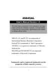
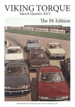
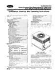
1
PARTS.
r---=::::==::::::-;::::::;-'
ACCESSORIES·
PRODUCT
PAC KA R D MOT 0 RCA R COM PAN Y
VOL. 28, NO. 11
NOVEMBER, 1954
Twin Ultramafic Transmission
The official name for the Gear-Start Transmission is "TWIN ULTRAMATIC TRANSMISSION" and will be
referred to as such in all future service publications.
Most all of the zones have completed the Twin Ultramatic Transmission schools with their dealers and according to reports, the service training panel covering the hydraulic system was highly received by the mechanics.
61
traffic and highway driving. After the engine and
transmission are thoroughly warmed up, and the
non-standard operation noted, make a hydrauHc
pressure test as outlined below:
HYDRAULIC PRESSURE TEST
To diagnose and isolate the cause of the faulty
operation a pressure test should be made of the
following hydraulic units:
(1)
(2)
(3)
(4)
(5)
(6)
(7)
(8)
This type of service training aid is planned for future
schools wherever it can be applied. We feel that a
better understanding of any and all units of the car will
result in a more accurate diagnosing of complaints
and better workmanship which means quicker and
better repair jobs for the Packard owners.
Front pump pressure.
High range clutch pressure.
Low brake top pressure.
Converter in pressure.
Converter Out pressure.
Direct drive clutch pressure.
Governor pressure.
Throttle pressure.
CEAR-ST.>\.RT IJL.TIlA .\ IATIC
TRA1~S-'IISSI0N
PHr.SSURE
TEST FORMS
Pictured are schools held recendy by the Los An·
geles Zone.
Twin Ultramatic Transmission
fro,,' Puml' 11)-fllO
1I/,~I_AII
&I""or """itl"""
R~od,nR'
HYDRAULIC TESTS
• P p,,,,t">n__ l~ In 2G ~1P1t-full Ih",I,I. bof",.
0""" 0"" •• n~.g<>--~b •. P"..~".c
_Hc.d,n~~
Hydraulic pressure tests are a most important
factor when diagnosing automatic transmission com~
plaints.
n'
P,,,;\l.," __
rull
,"~,"J<. ""f~,.
O,,~".:C'>-:>l.'<. !,,,,,,,u,.~
nor"" Pd,-.
_R">"'n~ H,,"I~
Il,~h R,n~c <.:1"1.<11 (21_Pf""'"r~ .I-.IJ be
"f ",,' m"", In;," IU II:>. UnO., pump
• n p,,.,,,,,,,.
If a complaint or trouble is not definitely located
or established, do not disassemble the unit until the
oi1level is checked, the car road tested and a hydraulic
unit pressure test is made. Too many times a unit is
disassembled. and when the inspection is made the
cause of the complaint cannot be found , because the
clue or evidence of the cause has been lost or
destroyed.
1'1'
",,00 RP~1
,R.aomc_
il,HI
ll ..... m.
P'''''''C
HRCP
~
'0 1'... "" .. _
I~ 10 ZII ~IPH C"'''~ft.r Pm'"
_H<adh"~ ~
U' P'~,"on
IlPM
.I<J(l
1I •• d,nl. ti\,~
p' l\.. i'MI_ZQ MPH_D.",."
S:o.dy lhron'"
-------u-
Dr;,',
R.od,n~
Ik, ~. TO!> 13)- 1'1 ..... '" ,hoold b< ,I", .. m"
~"t m., .. ,h.n lQ It.. "m"', 1"''''1' " ..... u,.
l.ow
1'1'
Dr
L n.TP
'D P,,,,,;,o>---VHl RP~'_R"odm~ ~\I-'_
~
D' 1""''''''11--"100 R!'M_H<lUl"'~
-----r-
D' Pus,'"'' Imme<H.'~I)·
An" UI"M,
_R<.don~ ~
. In many instances, " come backs" could be avoided
if a hydraulic pressure test was made after the work
was completed. for example: a certain part was
replaced, but the cause of the failure was not deter~
mined. Make a pressure test, it may give you the
cause which should be corrected thus avoiding a
repetition of the trouble.
!l,,«1 Om"o 16) Pr ...... , •• oo..ld b< ,he Am. 0< M'
m",.., ,h.n IQ II» "..,!.r pomp P""''''''
n ' !'. .. ,hun 15 t" IS Mrli
1'1"
001'
-R •• d,n1l<ij.iW """""'Q""
Gov.'nor (71-13 MPH
Co.,,'orl« In fil-tOO RPM U' 1'",,,,,,,,
_l! •• djn~
' ~MPH
"!lefor. Dtr""t Om"'-_H •• d,"~
_R=lin~
MPH
_R'NI",~
5E MPII
-RudJng~
RP~'
_Readln.~
~
Th",tII. 181_400
_ 11~",hn, ~72
Yull ThroItJ.
Vir"" Oli,'. r" g-.r"<l
-R<>d"" ,u:B""'
K"kdQwn
_R C'd"'~_
_R.ad'n,~
C"""e,'", 0..1 I;)-D ' P""II.,n I~ 10 II MPH
CW"'e,'e, Dr,,,,
-R"d,"l~
No'., R<d n~"r .. IndIO.'. «1,",«1 p,"",r ..
'I) ""''';on :0;,." Gear 5,.,t.
0 ' 1'00,,.,,,,,· Go" SI.,I.
t"!~P~"""
""""",ng '<m~ra'
,ok..., .1 11<1"".1
FLUID LEVEL
The fluid level should always be checked and
brought up [Q the full mark before any diagnosis is
made. Low fluid level can be the cause of many complaints ranging from excessive noise to a noticeable
slip in any or all of the operating ranges.
Fig. 1
NOTE: When making pressure tests, use th e
pressure fest forms shown in Fig. 1. The figures
below the lines on the form indicates correct
pressures.
ROAD TEST
After the oil level is brought up to the full mark,
road test the car to determine if correcting the oil
level has corrected the complaint. The road test
will also warm up the engjne and transmission to
operating temperature necessary to make an accurate
pressure test.
TOOLS
The necessary special tools required to make a
complete hydraulic pressure test on the Twin
Ultramatic Transmission are:
PK·23
Drive the car with frequent stops and starts, at low
speed, accelerating, and~at medium ~1 speeds, similar
to the conditions that would exist in driving in heavy
Special Test Pan Adapter, Throttle Pressure
Adjusting Wrenches and Gauge Hose Extensions .
PU·300 Three Gang Pressure Test Gauge.
62
PREPARATiON
4. Direct Drive Clutch-Conve rter In-Converter
Out.
5. Direct Drive Clurch-Governor-Co nverter In .
As most of the pressure tests are taken with tbe
car in motion at various speeds, the gauge should be
in the driver's compartment where it can be seen
while driving.
CONVERTER OUT PRESSURE
To ta ke the converter out pressure, a special tee
connection will be required. Install and braze a
Ys" male nipple into one end of a YsII tee.
Remove the flexible tubing from the left fresh air
duct, thread the gauge hoses through [he left fresh
air grille, out of the air duct and down to (he trans·
mission . "See Fig. 2 for location of the pressure
test take-off poinrs."
o 0
'~ o
(U PPER
FITTING)
8 --+--Ho
Remove the upper oil cooler tube adapter from the
side of the bell housing and install the special tee
connection in the bell housing. Install the oil cooler
tube adapter in the tee and reconnect the cooler cube.
t'See Fig. 3." Connect a gauge hose to th e tee
connection.
7
THROTTLE PRESSURE AND LOW
BRAKE TOP PRESSURE
o
The throtde pressure and low brake top pressure
test take-off points are located on the control assembly.
"See Fig. 4 ." To m a ke these tests, follow the procedure outlined:
BonOM VIEW
Fig. 2
Three pressures can be taken at one time; therefore;
study the nature of the trouble [0 determine (he
combination of pressures that may be at fault.
Suggested list of pressure test combinations without
removing the transmission oil pan:
1. Front Pump-High Range Clutch-Converter 10.
Fig. 4
2. Front Pump-Direct Drive Clutch-Converter In.
3. Front Pump-Converter In-Converter Out.
(a) Drain the oil, remove the transmission oil pan
and screen.
63
(b) Install the test pan adapter and gasket with
the adapter elbow tube on the left side and toward
the front of the car.
The throttle pressure should be 23 lbs. at 400 RPM
with the oil at operating temperature. The throttle
pressure ad justing SCrew is shown in Fig. 5. It can
be adjusted by removing tbe rubber plug in tbe
adapter and using the two small wrenches through
the opening as shown in Fig. 6. Be sure to recheck
the pressure after the adjusting SCrew lock nut is
tightened.
Thread two of tbe gauge boses through the elbow
tube on rhe adapter.
(c) Remove tbe Ys' pipe pluff "A" from tbe botlom
of tbe low brake and install a Ys' elbow in this opening.
Connect one of the gauge hoses to the elbow.
Suggested list of pressure test combinations with
gauges connected to the control body:
Remove the Ys' pipe plug "B" from the tbrottle
valve body and install a Ys' elbow in this opening.
Connect the other gauge hose to this elbow.
1. Throttle-Low Brake Top-Higb Range Clutcb.
2.
3.
4.
S.
(d) Install the two oil sucdon tube extensions as
shown in Fig. 4 and install the oil pan and gasket,
Reinstall the oil that was drained out or the same
amount of new oil.
Throttle-Low
Throttle-Low
Tbrottle-Low
Tbrottle-Low
Brake Top-Direct Drive.
Brake Top-Governor.
Brake Top-Frnnt Pump.
Brake Top-Converter In_
After the pressure tests have been completed and
the readings posted on the pressure test form, com·
pare your pressures with those on the test form.
Careful study of the pressures in conjunction with
tbe hydraulic cbarts will greatly aid you in diagnosing
troubles.
NOTE: The tbrottle pressure is a very important
pressure as it controls most other pressures in the
system, controls upshift, clutch engagements and disengagements. Therefore, it is important that thronle
pressure be accurate.
Voltage Regulator Testing
Procedure
DELCO-MODEL 1118829
5402-06-11 -13-26-31
Field reports indicate that the importance of checking the voltage setting of Model 1118829 type regulatOrs with a batte,.y ill the circllit is nOt fully appreciated
by all concerned.
The Model 1118829 type regulators do not include
a acceleratOr or "kicker" coil on the voltage regulator
unit. As a result: the rate of armature vibration is
slower than that of earlier types and tbe ·voltage setting
call be clucked accllrately only wbell a battery is c01mected
ill the cha,-gillg circllit. For this reason~ it is specified
that voltage regulator checks on these regulators be
made with a fixed .k.J:·ohm resistor of not less than
25 watts capacity connected in series with the battery.
Fig. 5
THROTTLE PRESSURE ADJUSTMENT
,Before attempting to adjust the throttle pressure,
cbeck all of the throttle linkage adjustments as described in the "Maintenance Section " of your Gear·
Start Ultramatic Transmission Training Booklet.
If Model 1118829 rype regulators are checked by
using a U ·ohm resistor in place of the battery (as
was previously recommended 01..1 earlier models),
the indicated volhlge settiug will t . d to be erratic and
alw(J.Ys will be comiderably lowe,. tball tbat obtained
with ~t battery ill tbe circllit.
The use of a fixed 7;(·ohm resis[Qr connected in
series with the battery is entirely satisfactory for
checking the voltage regulator setting 011 bot/; old ~lI/d
lIew type regulators in eirher 6· or l2·volt models.
Headlight Aiming
The AMA specifications on head lamp aiming has
been changed in respect to rhe height of the light beam.
Please make this change on page 22 "Electrical
Section" of your Service Manual. In the 2nd para·
graph under "Head light Aiming", change 3'
dimension to 2".
Fig . 6
64
PRINTED IN U.S.A.