1
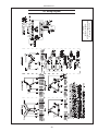
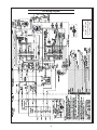
OM2-4 For Models: M1064H and M1066H OPERATOR’S MANUAL Marine Generators | Marine Diesel Engines | Land-Based Generators — CALIFORNIA — Proposition 65 Warning: Diesel engine exhaust and some of its constituents are known to the State of California to cause cancer, birth defects, and other reproductive harm. Northern Lights 4420 14th Avenue N.W. Seattle, WA 98107 Tel: (206) 789-3880 Fax: (206) 782-5455 Copyright ©2013 Northern Lights, Inc. All rights reserved. Northern Lights™, and the Northern Lights logo are trademarks of Northern Lights, Inc. Printed in U.S.A. PART NO.: OM2-4 7/13 OPERATOR'S MANUAL #OM2-4 for Models: M1064H and M1066H Read this operator's manual thoroughly before starting to operate your equipment. This manual contains information you will need to run and service your new unit. Table of Contents INTRODUCTION ....................................................2 Models Included .................................................2 Model Numbers ..................................................2 Serial Numbers ...................................................2 Fuels - General ................................................. 18 Crankshaft Vibration Damper (6 Cyl.) ............ 19 Fuel Filters ....................................................... 19 The Fuel System ...................................... 20 - 21 High Pressure Common Rail ................... 20 - 21 Turbocharger .................................................... 21 Turbo Boost ..................................................... 21 Cooling System - General ................................ 21 Engine Coolant Specifications ................. 22 - 23 Cooling System Flushing ......................... 23 - 24 Heat Exchanger Cleaning ................................ 24 Zinc Electrodes ................................................ 24 Raw Water Pump ............................................. 24 Generator Ends ................................................ 25 Electrical System - General ................................5 Booster Batteries .............................................. 25 Battery Care ..................................................... 25 Winterizing / Out-of-Service ........................... 25 WARRANTY ............................................................3 SAFETY RULES ...............................................3 - 7 LOCK OUT / TAG OUT PROCEDURES ............8 COMPONENT LOCATIONS M1064 .............................................................. 10 M1066 ...............................................................11 ENGINE & GENERATOR CONTROL PANELS Series 3B .......................................................... 12 EMISSION-RELATED INSTALLATION & INSTRUCTIONS................................................... 13 TROUBLESHOOTING Electrical .......................................................... 26 Engine ...................................................... 26 - 28 OPERATING PROCEDURES Before Starting ................................................. 13 Shutdown Procedures ...................................... 13 Break-In Period ................................................ 14 WIRING DIAGRAMS AC Electrical .................................................. 29 DC Electrical ........................................... 30 - 31 SERVICING SCHEDULE CHART .................... 15 SERVICING Lubrication - General ....................................... 16 Checking Oil .................................................... 16 Oil Changes ..................................................... 16 Changing Oil Filter .......................................... 16 Air Filter .......................................................... 16 Valve Clearances ...................................... 17 - 18 ON-BOARD SPARE PARTS.............................. 32 Proprietary Information This publication is the property of Northern Lights, Inc. It may not be reproduced in whole or in part without the written permission of Northern Lights, Inc. © Northern Lights, Inc. All rights reserved. Litho U.S.A. Publication number OM2-4 7/13 OM2-4 7/13 1 Introduction Failures begin with minor problems that are overlooked and become amplified when not corrected during routine maintenance. Servicing of marine engines and generator sets presents unique problems. In many cases boats cannot be moved to a repair facility. Marine engines cannot be compared to the servicing of automobiles, trucks or even farm equipment. Failures often occur in remote areas far from competent assistance. Marine engines are taxed far more severely than auto or truck engines; therefore, maintenance schedules must be adhered to more strictly. s As operator, it is your obligation to learn about your equipment and its proper maintenance. This is not a comprehensive technical service manual. Nor will it make the reader into an expert mechanic. Its aim is to aid you in maintaining your unit properly. Model Numbers Model numbers give the unit's application, block model, aspiration, and RPM: 1064 or 1066 M M - Northern Lights marine generator set M1064H = + H Model number 106 mm bore, 4 Cylinder or 106 mm bore, 6 Cylinder Northern Lights® turbocharged, marine diesel generator set with a John Deere Powertech Tier II 4045 engine block with an electronically controlled fuel system, high pressured common rail. M1066H = + H - High Powered Northern Lights® turbocharged marine generator set with a John Deere Powertech Tier II 6068 engine block with an electronically controlled fuel system, high pressured common rail. Serial Numbers When referencing Northern Lights equipment by serial number, please refer only to the number stamped on the Northern Lights® serial number plate. OM2-4 7/13 2 Revised 7-10-13 Warranty A warranty registration certificate is supplied with your set. The extent of coverage is described in the Limited Warranty Statement. We recommend that you study the statement carefully. followed. If further information is needed, please contact an authorized dealer or the factory. NOTE: If the warranty is to apply, the servicing Safety Rules instructions outlined in this manual must be NOTICE: Accident reports show that careless use of engines causes a high percentage of accidents. You can avoid accidents by observing these safety rules. Study these rules carefully and enforce them on the job. IMPORTANT SAFETY INSTRUCTIONS. Electromagnetic equipment, including generator sets and their accessories, can cause bodily harm and life threatening injuries when improperly installed, operated or maintained. To prevent accidents be aware of potential dangers and act safely. on parts and components from outside suppliers that is not reproduced in this manual. Consult the suppliers for additional safety information. Learn how to operate the machine and how to use the controls properly. Only trained personnel should operate machines, or work on or around them. READ AND FOLLOW ALL SAFETY INSTRUCTIONS IN THIS MANUAL, PRIOR TO THE INSTALLATION OF ANY GENERATOR SET OR ACCESSORY. KEEP THESE INSTRUCTIONS FOR FUTURE REFERENCE. Keep you machine in proper working condition. UNAUTHORIZED MODIFICATIONS TO THE MACHINERY MAY IMPAIR ITS FUNCTION AND SAFETY PARAMETERS. Prevent Bypass and Accidental Starting Recognize Safety Symbols and Instructions In addition to the information found in this section, this operator’s manual uses three different signal words to outline potential dangers of a specific nature. Do not start engine by shorting across start terminal. Engine will start if normal circuitry is bypassed, creating a hazard by runaway machinery. DANGER indicates a hazardous situation which, if not avoided, will result in death or serious injury. WARNING indicates a hazardous situation which, if not avoided, could result in death or serious injury. CAUTION indicates a hazardous situation which, if not avoided, could result in minor or moderate injury. Start engine only from operator’s station. Follow All Safety Instructions Carefully read and understand all safety messages in this manual and on your machine’s safety signs. Keep signs in good and clean condition. Replace missing or damaged signs. Be sure new equipment components and repair parts include the current safety signs. For replacement signs, proper placement of safety signs or clarification on any safety issue, consult your Northern Lights dealer or the factory. There can be additional safety information contained Handle Fuel Safely - Avoid Flames Diesel is highly flammable and should be treated with care at all times. Do not refuel while smoking or when near sparks or open flame. ALWAYS STOP ENGINE BEFORE FUELING MACHINE. Always fill portable fuel tank outdoors. Never fuel a hot engine. OM2-4 7/13 3 Added 6-11-12 Safety Rules Prevent accidental discharge of starting fluids by storing all cans in a cool, safe place, away from sparks or open flame. Store with cap securely on container. Never incinerate or puncture a fuel container. Operating equipment requires the full attention of the operator. Do not use radio or music headphones while operating machinery. Prevent fires by keeping machine clean of accumulated trash, grease and debris. Always clean any spilled fuel as swiftly as possible. Do not store oily rags, which can ignite and burn spontaneously. Practice Safe Maintenance Understand all service procedures before starting work. Keep area clean and dry. Never lubricate, service, or adjust machine while it is in operation. Be prepared if a fire starts. Keep a first aid kit and fire extinguisher handy. Keep emergency contact numbers for fire department, doctors, ambulance and hospital near the telephone. Keep hands, feet and clothing away from powerdriven equipment. When shutting down an engine, disengage all power and operator controls. Allow the engine to cool completely before beginning any service work. Service Machines Safely Securely support any machinery elements that must be raised for service work with support or lifting machinery specifically intended for that purpose. Do not wear a necktie, scarf, necklace, rings or other jewelry, or any loose clothing when working near moving parts. Tie long hair behind your head. If any of these items get caught in moving machinery, severe injury or death could result. Keep all parts in good conditions and properly installed. Fix damage immediately. Replace any worn or broken parts. Remove any build up of grease, oil or debris. Check for any loose electrical connections or faulty wiring. Disconnect battery ground cable (-) before making any adjustments or service work. Look completely around engine to make sure that everything is clear before starting. Stay Clear of Rotating Drivelines Wear Protective Clothing Entanglement in rotating drivelines can cause serious injury or death. Keep shields in place at all times. Make sure that rotating shields turn freely in pace with the drivelines. To prevent catching anything in moving machinery, always wear close fitting clothes and safety equipment appropriate to the job. Prolonged exposure to loud noise can cause hearing loss or impairment. Wear suitable authorized hearing protection, such as earmuffs or plugs to protect against loud noises. Do not wear loose fitting equipment around rotating drivelines. Stop the engine and make sure that all moving parts have stopped before making any adjustments, connections, or performing any other type of service to the engine or other driven equipment. OM2-4 7/13 4 Added 6-11-12 Safety Rules (Continued) To Avoid Hazards: • Fill batteries only in well-ventilated areas. • Wear appropriate eye protection and rubber gloves. • Never use air pressure to clean batteries. • Wear appropriate ventilation equipment to avoid inhaling fumes when adding electrolyte. • Do not spill or drip electrolyte. • Use correct jump-start procedure if required. Install all Safety Guards Direct contact with rotating fans, belts, pulley and drives can cause serious injury. Keep all guards in place at all times during engine operation. If acid is spilled on skin or in eyes: 1. Flush skin with water. 2. Apply baking soda or lime to help neutralize acid. 3. Flush eyes with water for 15-30 minutes. 4. Get medical attention immediately. If acid is swallowed: 1. DO NOT induce vomiting. 2. Drink large amounts of water or milk, without exceeding 2 liters (2 quarts) 3. Get medical attention immediately Wear close-fitting clothes. Stop the engine and be sure all fans, belts, pulleys and drives are stopped before making adjustments, connections, or cleaning near fans and their components. Do not allow anything on your person to dangle into or come in contact with a moving fan, belt, pulley or drive. Fans can act as vacuums and pull materials up from below, so avoid that area as well while in service. Safe Battery Handling Battery posts, terminals, and related accessories can contain lead and lead compounds, chemicals known to the State of California to cause cancer and reproductive harm. Wash hands after handling. Prevent Battery Explosions Battery gas is highly flammable. Battery explosions can cause severe injury or death. To help prevent battery explosions, keep sparks, lighted matches and open flame away from the top of battery. When checking battery electrolyte level, use a flashlight. Handle Chemical Products Safely Direct exposure to hazardous chemicals can cause serious injury. Among the potentially hazardous chemicals that may be used with Northern Lights products are lubricants, coolants, paints and adhesives. Never check battery charge by contacting the posts with a metal object. Use a volt-meter or hydrometer. Frozen batteries may explode if charged. Never charge a battery that has not been allowed to warm to at least 16oC (60oF). Always remove grounded (-) battery clamp first and replace ground clamp last. All potentially hazardous chemicals come with a Material Safety Data Sheet (MSDS). The MSDS provides specific details on chemical products, including physical hazards, safety procedures and emergency response techniques Sulfuric acid in battery electrolyte is poisonous and strong enough to burn skin, eat holes into clothing and other materials, and cause blindness if splashed into eyes. OM2-4 7/13 5 Added 6/11/12 Safety Rules (Continued) Read and understand the MSDS for each chemical before you start any job that includes it. Follow the procedures and use appropriate equipment exactly as recommended. engine has been shut off. Do not remove a filler cap unless it is cool enough to comfortably grip with bare hands. Slowly loosen cap to relieve pressure before opening fully. Contact your Northern Lights dealer or Northern Lights factory for MSDS’s used on Northern Lights products. Avoid High Pressure Fluids Work in Well Ventilated Areas Exhaust fumes from engines contain carbon monoxide and can cause sickness or death. Work in well ventilated areas to avoid prolonged exposure to engine fumes. If it is necessary to run an engine in an enclosed area, route the exhaust fumes out of the area with an approved, leak proof exhaust pipe extension. Relieve pressure prior to disconnecting pressurized lines. Escaping fluid under pressure can penetrate the skin causing serious injury. Always relieve pressure before disconnecting hydraulic or other pressurized lines. Tighten all connections firmly before re-applying pressure. If searching for leaks, use a piece of cardboard. Always protect your hands and other body parts from high-pressure fluids. Remove Paint Before Welding or Heating If an accident occurs, see a doctor immediately. Any high pressure spray injected into the skin must be removed within a few hours to prevent the risk of gangrene or other infection. Hazardous fumes can be generated when paint is heated by welding, soldering or using a torch. To avoid potentially toxic fumes and dust, remove paint before heating. Avoid Heating Near Pressurized Fluid Lines • Remove paint a minimum of 100 mm (4 in.) from the area that will be affected by heat. • If paint cannot be removed, wear an approved respirator. • If you sand or grind paint, use an approved respirator. • If you use solvent or paint stripper, remove stripper with soap and water before welding. Remove solvent or paint stripper containers from the area. • Allow at least 15 minutes for fumes to disperse before welding or heating. Do not use a chlorinated solvent in an area where welding will occur. Work only in areas that are well ventilated. Dispose of paint and solvent properly. Flammable spray can be generated by heating near pressurized fluid lines, resulting in severe burns and bodily injury. Pressurized lines can rupture when heat goes beyond the immediate flame area. Do not weld, solder or use a torch or open flame near pressurized lines or other flammable fluids. Do Not Open High-Pressure Fuel System Service Cooling System Safely Opening a pressurized cooling system can release explosive fluids and causing serious burns. Before opening any pressurized cooling system, make sure the Many Northern Lights engines use high-pressure fuel injection. High-pressure fluid remaining in fuel lines can cause serious injury. Do not disconnect or attempt any repair of fuel lines, sensors, or other OM2-4 7/13 6 Added 6/11/12 Safety Rules (Continued) components between the high-pressure fuel pump and nozzles on engines with high pressure fuel systems. material containing asbestos. Keep all bystanders away from any area where asbestos dust may be generated. ONLY AUTHORIZED TECHNICIANS CAN PERFORM REPAIRS ON AN HIGH PRESSURE FUEL INJECTION SYSTEMS. Use Proper Lifting Equipment and Techniques Avoid Hot Exhaust Lifting heavy components incorrectly can cause severe injury or damage to machinery. Avoid unbalanced loads. Do not use lifting eyes. Lift the generator set using lifting bars inserted through the lifting holes on the skid. Follow all recommended removal and installation procedures in this and associated Northern Lights manuals. Avoid exposure to and physical contact with hot exhaust gases. Exhaust parts and streams can reach high temperatures during operation, leading to burns or other serious injury. Cleaning exhaust filters can also lead to exposure to hot exhaust gas and the injury risk associated with it. Avoid exposure to and physical contact with hot exhaust gases when cleaning exhaust filters. Use Proper Tools During auto or manual/stationary exhaust filter cleaning operations, the engine will run at elevated temperatures for an extended period of time. Exhaust parts and streams can reach high temperatures during operation, leading to burns or other serious injury. Makeshift tools and procedures can create safety hazards. Always use appropriate tools for the job. Use power tools only to loosen threaded parts and fasteners. For loosening and tightening hardware, always use the correct sized tools. Avoid Harmful Asbestos Dust Do not use US measurement tools on metric fasteners, or vice versa. Use only service parts that meet Northern Lights specifications. Inhaling asbestos fibers may cause lung cancer. Avoid breathing any dust that may be generated when handling components containing asbestos fibers, including some gaskets. Dispose of Waste Properly Disposing of waste improperly can threaten the environment and lead to unsafe working conditions. Potentially harmful waste used in Northern Lights equipment can include oil, fuel, coolant, filters and batteries. The asbestos used in these components is usually found in a resin or otherwise sealed. Normal handling of these components is not dangerous, as long as airborne dust containing asbestos is not generated. Avoid creating dust. Never use compressed air for cleaning. Avoid brushing or grinding materials containing asbestos. When servicing, wear an approved respirator. A special vacuum cleaner is recommended to clean asbestos. If this vacuum is not available, apply a mist of oil or water on the Use leakproof containers to drain fluid. Do not use food or beverage containers that may mislead someone into drinking from them. Do not pour waste onto the ground, down a drain or into any water source. OM2-4 7/13 7 Added 6/11/12 Lock Out / Tag Out Procedures Scope During maintenance, repairs or retooling of a Northern Lights generator set, simply turning the machine off or unplugging it while it is being worked on does not give enough protection to others who are not performing the maintenance or repair. Many serious accidents happen when someone thought the machine was turned off, or all of its energy was safely blocked or released. General Policy If shutting off of air, water or other material cannot be achieved at the local supply valve, shut off valves further back in the system and re-check the bleed-off point until complete shut-off is achieved. To avoid dangerous or hazardous situations, refrain from any of the following: • Removing or bypassing a guard or other safety device • Placing any part of your body in a position where you could be caught by moving machinery. • Cleaning or oiling machinery when in operation. • Adjusting circuits, chillers, pumps, air handlers, valves, circuit breakers or fans while in operation. • Working on piping or high pressure systems. Affix a DO NOT OPERATE tag to each valve handle that requires shut off. Each DO NOT OPERATE tag must be signed and dated by the authorized technician servicing the equipment. Lock Out/Tag Out Instructions Air Hose Connected Pneumatic Equipment Lock Out/Tag Out Instructions Electrical Equipment Equipment connected to the compressed air system through an air hose with a detachable fitting must be shutdown and unplugged. Excess air must be bled prior to removing the air hose, prior to any maintenance or Be sure the equipment’s ON/OFF switch is in the OFF repair activities. position and is unplugged from any electrical source before attempting to perform any type of work on the equipment. Affix a DO NOT OPERATE tag to the air hose near the Obtain an electrical plug cap cover with a lockset. Secure detachable fitting. Each DO NOT OPERATE tag must be the plug terminal end using the electrical plug lockout cap. signed and dated by the authorized technician servicing Lock the cap and retain the key. the equipment. Check that the equipment cannot be operated by activating the ON switch. If the equipment is directly wired into an electrical box with a shut off switch, obtain a lock pad and/or the appropriate Stored Energy colored tags and place the lock and tag through the shut off lever. Retain the key until the repair is completed and the machine is safe to start. Be certain the shut off lever Immediately after applying Lock Out or Tag Out devices, is in the OFF position before restarting. NEVER give a ensure that all potentially hazardous stored or residual lock out key to unauthorized personnel. energy is relieved, disconnected, restrained and otherwise rendered safe. If the equipment is directly wired into an electrical box without a shut off switch and lock out capability, then a Verification of Isolation circuit breaker lock out will be required. Obtain a circuit lock and tag set. Install the lock onto the circuit breaker box. Ensure the unit ON/OFF switch is in the OFF position Verify the machinery or equipment is actually isolated and before restarting. de-energized prior to beginning work on a machine or on equipment that has been locked out. Lock Out/Tag Out Instructions Pneumatic and Hydraulic Equipment Restarting Procedures For servicing pneumatic and hydraulic equipment, the following additional procedures must be implemented, following completion of lock out/tag out procedures for the unit to be serviced: Follow the procedures below prior to restoring energy: • Ensure that all machinery or equipment is properly reassembled. Inspect the machinery or equipment to verify non-essential items have been removed. • Ensure that all personnel are safely outside danger zones. Notify personnel that lock out/tag out devices have been removed and energy will be reapplied. • Only authorized personnel may remove lock out/tag out devices or notices. Shut off air, water or supply valves at the equipment to be serviced. Check the local bleed-off point for completed release of pressurized air, water or oil. OM2-4 7/13 8 Notes OM2-4 7/13 9 Component Locations Figures 1 & 2: M1064H 1. 2. 3. 4. 5. 6. 7. Coolant Fill Expansion Tank DC Alternator Lube Oil Fill Oil Filter Lube Oil Dipstick Lube Oil Drain 8. 9. 10. 11. 12. 13. Electric Starter Heat Exchanger Zinc (2) Oil Pan Turbocharger Heat Exchanger Thermostat Cover 14. Optional Hydrolastic Mounts 15. Drive Belt Cover 16. Fuel Manifold 17. Fuel Filter (Secondary) 18. Aftercooler OM2-4 7/13 10 19. 20. 21. 22. Heat Shield Junction Box Wet Exhaust Elbow Electronic Control Unit Component Locations Figure 3 & 4: M1066H 1. 2. 3. 4. 5. 6. Coolant Fill Expansion Tank DC Alternator Lube Oil Fill Oil Filter Lube Oil Dipstick 7. 8. 9. 10. 11. 12. Lube Oil Drain Starter Heat Exchanger Zinc (2) Turbocharger Heat Exchanger Thermostat cover 13. Optional Hydrolastic Mounts 14. Drive Belt Cover 15. Fuel Manifold 16. Fuel Filter (Secondary) 17. Aftercooler OM2-4 7/13 11 18. 19. 20. 21. Heat Shield Junction Box Electronic Control Unit Optional PTO Northern Lights Control Panel 1. SHUTDOWN BYPASS SWITCH This switch bypasses the safety shutdown feature during the starting process. 2. ENGINE CONTROL SWITCH To start the engine, hold this switch in the START position until the engine is running. NOTE: Excessive cranking of marine sets equipped with water lift muffler systems can cause engine damage. After the engine starts, release the switch and it will return to RUN position. To stop the engine, hold the switch in the STOP position. 3. OIL PRESSURE GAUGE The oil pressure gauge shows the oil pressure in the engine lubricating system. If the pressure drops below 15 PSI at a speed higher than idling, stop the engine and investigate. Figure 5: Series 3B Generator Control Panel 4. COOLANT TEMPERATURE GAUGE Water temperature gauge shows the temperature of the cooling water. If the gauge registers over 200° (93.30C) or drops below 140° (600C), stop the engine and investigate. 5. HOUR METER Keeps track of the engine running time. 6. DC VOLTMETER When the engine is running, it indicates the voltage output of the alternator. OM2-4 7/13 12 revised 3-19-13 Emission-Related Installation & Instructions Failing to follow these instructions when installing a certified engine in a vessel violates federal law (40 CFR 1068.105(b)), subject to fines or other penalties as described in the Clean Air Act. a turbocharged engine and 48” (1200 mm) for a nonturbocharged unit, measured at the engine exhaust elbow. If you install the engine in a way that makes the engine’s emission control information label hard to read during normal engine maintenance, you must place a duplicate label on the vessel, as described in 40 CFR 1068.105. The installed exhaust system should not create exhaust back pressure greater than 30” (760 mm) of water for Operating Procedures NOTE: If there is a governor locked at a specific speed on the generator set, there may not be a slow idle function, so in that case operate the engine at high idle for 1 to 2 minutes before adding load. If the stand-by generator set is loaded as soon as it reaches rated speed, this procedure would not apply. BEFORE STARTING 1. Check the water level by removing the pressure cap from the expansion tank. In order to give the cooling water room to expand, the level should be about 1 3/4 in. (4-5 cm) below the filler cap sealing surface when the engine is cold. When filling with coolant, the venting cock on top of the turbocharger should be opened to ensure that no air pockets form in the cooling system (see Service Point #14). Operating 1. Check Gauges Often: Oil pressure must be above 29 PSI (if not above 15 PSI within 5 seconds of starting, the engine should be stopped and the problem should be explored). Normal oil pressure is 50 PSI at rated load speed (1800 to 2500 RPM). Oil temperature should be 1150C (2400F) for normal operating temperature. The D.C. voltmeter should read between 13 and 14 volts (26-28 volts, 24 volt systems). 2. Check AC voltage and frequency meters (Series 4 Panel). If gauges deviate from normal levels, shut down the set and investigate. 3. Check belt for good alignment. 4. Let the unit run unloaded for a three to five minute warm-up period before applying load. 5. Do not add full electrical load until engine is at maximum operating temperature. CAUTION: Use protective clothing and open the filler cap carefully when the engine is warm to prevent burns. 2. Check the oil level in the crankcase with the dipstick. The oil level should be between the “waffled area” and the “oo”. Never allow the level to go below the “oo”. Always add the same viscosity of oil as is already in the crankcase (see Service Point #1). 3. Check the fuel tank level and open any fuel valves. 4. Disengage clutch, if equipped. 5. Close the seacock, check and clean the strainer and reopen the seacock. 6. Place the battery switch in the ON position. NOTE: The battery switch must always be kept ON while the engine is running. If the switch is turned OFF while the engine is running, the battery charging regulator could be ruined. NOTE: If engine dies while under load, immediately remove load and restart engine. Turbocharger parts could overheat if the oil flow stopped. Starting 1. While holding the Shutdown Bypass switch in the ON position, push the Engine Control switch to the START position. 2. As soon as the engine starts, release both switches. Do not crank the starter for more than 20 seconds. 3. If the engine fails to start the first time, be sure the starter has stopped before re-engaging. Wait 2 minutes before starting engine again. Shutdown 1. Turn the Engine Control Switch to the OFF position. 2. Close the sea cock and fuel valves, and put the battery switch in the OFF position if the unit will be off for an extended period. NOTE: Do not turn the battery switch to OFF while the engine is running. OM2-4 7/13 13 Updated 3-19-13 Operating Procedures SHUTDOWNS AND ALARMS 1. Your unit is fitted with a system to protect it from high water temperature or low oil pressure. a. Generator sets have shutdown systems to stop the engine. They have no warning horns. b. Other alarms and shutdowns are available as optional equipment. BREAK-IN PERIOD 1. Your engine is ready to be put into service. However, the first 100 hours on a new or reconditioned engine are critical to its life and performance. This is especially true of an engine that runs at a constant speed such as a generator engine. NOTE: Do not rely on your warning or shutdown 2. Operate the engine under various conditions, system to the exclusion of careful gauge monitoring. Watching your gauges can prevent damage to the unit particularly heavy loads with minimal idling, to and dangerous power losses. help seat engine components properly. 2. Do the following when your shutdown system is 3. Oil consumption is greater during break-in as piston activated: rings take time to seat. a. Check the temperature gauge. If the temperature is above 205°F (97°C), shut off the engine immediately. 4. Your engine comes equipped with break-in oil. b. Use the Trouble Shooting Guide on pages 22- 24 Change engine oil and filter at 50 hours using API to isolate the cause of the overheat. Service Category CC, CD, or CE break-in oil. Change the oil and filter again at 100 hours. (ConCAUTION: Do not remove the water fill cap of an sult the lubricants section for oil recommendation.) overheated engine. Escaping high temperature steam can cause severe burns. Allow the engine to cool and then remove the cap slowly, using protective clothing. 5. Frequently check the engine temperature and oil pressure gauges. c. Make repairs and restart after the temperature gauge registers below 180°F (83°C). d. Watch the temperature gauge regularly and turn off the unit if the temperature rises above 200°F (94°C). Repeat the troubleshooting process. 3. If the shutdown is activated and the temperature gauge shows temperature within normal temperature range: a. Check the engine crankcase oil level. b. If the oil level is low, fill with recommended lubricating oil and restart. Watch the oil pressure gauge carefully and shut off the engine if it does not show a normal reading after a few seconds of operation. c. If the oil level was normal, DO NOT restart the engine. Call your Northern Lights or Lugger dealer for assistance. OM2-4 7/13 14 Updated 9-23-10 Service Schedule Chart The Servicing Schedule Chart below shows the service schedule required for proper maintenance of your marine engine or generator set. More detailed coverage of each Service Point (SP) is listed on the page noted in the ‘page’ column. DAILY: SP1 Check oil level in engine SP8 Check primary fuel filter SP15 Check coolant water level SP26 Check crankcase vent system filter svc. indicator button AFTER FIRST 50 HOURS: SP2 Change engine oil SP3 Change lube oil filter EVERY 50 HOURS: SP21 Check electrolyte in batteries AFTER FIRST 100 HOURS/ EVERY TWO WEEKS 5: SP2 Change engine oil after first 100 hrs., then check every 2 wks. SP3 Change oil filter after first 100 hrs., then check every 2 wks. SP7 Check crankshaft vibration damper7 SP15 Check coolant level EVERY 250 HOURS: SP2 Change engine oil SP3 Change oil filter SP4 Check air cleaner SP19 Check zincs SERVICE POINT PAGE EVERY 500 HOURS / YEARLY: SP4 Replace air cleaner SP5 Check belt condition SP9 Change primary filter element (Racor) SP10 Change secondary fuel filter SP14 Check turbocharger boost pressure SP16 Check cooling system SP20 Change impeller in raw water pump SP22 Check the state of the charge of the batteries SP25 Check engine mounts SP26 Clean crankcase vent system, change element at 500 hrs. SP27 Check air intake hoses SP29 Check electrical ground connection EVERY 2000 HOURS: SP6 Check & adjust valve clearance SP7 Check crankshaft vibration damper SP16 Flush cooling system SP17 Check and clean heat exchanger SP23 Test thermostats SP30 Check aftercooler, clean air side 50 Hours 100 Hours 250 Hours 2) 2) 1) 1) • • • 2) 2) 5) 1) 1) OPERATION DAILY ENGINE: SP1 SP2 SP3 SP4 SP5 SP6 SP7 SP25 SP27 12 12 12 12 SP8 SP9 SP10 15 15 14 Check primary filter (Racor) Change primary filter element (Racor) Change secondary fuel filter SP13 SP14 SP26 SP30 17 17 17 21 Check air, oil & cooling water lines for leakage Check boost pressure Check crankcase vent system Check aftercooler, clean air side SP15 SP16 SP17 SP19 SP20 19 19 20 20 20 Check coolant level Check and flush cooling system Check and clean heat exchanger Check zinc electrodes Change impeller in raw water pump SP21 SP22 SP23 SP29 21 21 Check electrolyte level in batteries Check condition of batteries with hydrometer Test thermostats Check electrical ground connection 13 15 Check oil level Change engine oil Change lube oil filters Check air cleaner Check belt condition Check valve clearances Check crankshaft vibration damper Check engine mounts Check air intake hoses • 500 Hours • • • • FUEL SYSTEM: • 3) 3) 4) 2) 4) • • • • TURBOCHARGER: 2) 2) COOLING SYSTEM: • • 7) • 2) 2) 2) 4) 2) 4) ELECTRICAL SYSTEM: • 6) • • • • • • • • 5) Replace damper every 4500 hours or after 60 months. 6) Check cooling system at 500 hours, flush at 2000 hours. 7) Check hoses and o-rings on crankcase vent system, change element at 500 hours. OM2-4 7/13 15 • 2) 4) 2) 1) Change the oil and filter before the first 100 hours of operation during engine break-in. 2) Perform all maintenance once a year even if hour level has not been reached. 3) Consult manufacturer's maintenance schedule, note on chart. 4) Whenever necessary. 2000 Hours • Servicing LUBRICATION Break-in oil 1. Use one of the following during the first 100 hours of operation: a. John Deere Engine Break-In Oil b. API Service Category CC, CD, or CE oil c. ACEA Specification E1 2. Do not use John Deere PLUS-50 oil or engine oils meeting API CG4, API CF4, ACEA E3, or ACEA E2 performance levels during the first 100 hours of operation of a new or rebuilt engine. These oils will not allow the engine to break-in properly. Lubrication - General 1. Use only clean, high quality lubricants stored in clean containers in a protected area. 2. These oils are acceptable after the first 100 hours: a. ACEA Oil Sequence E5 and E4 b. API Service Category CI-4 or CH-4. c. ACEA Oil Sequence E3 multi-viscosity oil. 3. Use the proper weight oil for your average operation temperature. Air Temperature Single Viscosity Multi Viscosity Above 32°F (0°C) SAE-30W SAE15-40W -10°F to 32°F (-23°C to 0°C) SAE-10W SAE10-30W Below -10°F (-23°C) SAE-5W SAE5-20W SP2. OIL CHANGES 1. Using the oil recommended above, change the engine oil and filter after the first 50 hours of operation, the first 100 hours, and every 250 hours thereafter. 2. During intermittent cold weather operation, change oil every 100 hours or six weeks, whichever comes first. 3. Change oil at any seasonal change in temperature when a new viscosity of oil is required. a. Remove plug from outlet in base frame. Screw in owner-supplied drain hose. b. Open valve at oil pan outlet. After oil has been drained into suitable container, close valve, remove drain hose and replace plug in base frame outlet. c. Refill engine with recommended oil. 4. Engine Lube Oil Capacity: M1064H M1066H 21.6 qts. 33.3 qts. 20.5 liters 31.5 liters SP3. CHANGING OIL FILTER 1. Change the lube oil filter every 250 hours. 2. Use a filter wrench to remove old filter. Dispose of filter in approved manner. 3. Make sure the gasket from the old filter is removed and discarded. 4. Lubricate the rubber gasket on the new filter and screw it on nipple until gasket meet the sealing surface. 5. Using hands only, no wrench, tighten filter one-half turn farther. Overtightening can do damage to filter housing. 6. Fill engine with recommended oil. Start engine and check for leakage. Stop engine and check oil level. Add additional oil if necessary. 4. Some increase in oil consumption may be expected when SAE 5W and SAE 5-20W oils are used. Check oil level frequently. 5. Never put additives or flushing oil in crankcase. SP4. AIR CLEANER 1. Inspect air cleaner every 100 hours. Replace filter every 500 hours, or yearly, whichever comes first. 2. Clean the rubber tube at the cleaner. Loosen the hose clamp and the attaching strip for the cleaner. 3. Make sure the rubber tube is in good condition and that the new filter is absolutely clean and installed properly. 4. Start the engine and check for leaks. SP1. CHECK ENGINE OIL LEVEL 1. Check the oil level in the crankcase, with the oil dipstick, daily. 2. The oil level must be between the “Waffled area” and the “oo”. Never allow the level to go below the “oo”. 3. Always add the same viscosity of oil as is already in the crankcase. NOTE: Make absolutely sure no impurities enter the engine while changing the element. Do not run the engine with the air cleaner removed. OM2-4 7/13 16 Servicing SP6. VALVE CLEARANCES Valve Clearance Adjustment Specifications: Intake Valve Adjustment Clearance (Rocker arm to bridge).......................0.36 mm (0.014 in.) Exhaust Valve Adjustment Clearance (Rocker arm to bridge).......................0.46 mm (0.018 in.) Rocker Arm Adjusting Screw Jam Nut Torque.................................27 N•m (20 lb-ft) CAUTION: Disconnect the negative (-) battery terminal before starting valve adjustments to prevent accidentally starting the engine. Valve clearance must be checked and adjusted with the engine cold. The following special tools will be needed: JDE 820 or JDE 83 Flywheel Turning Tool. JDE 81-4 Timing Pin. 1. Remove rocker arm cover with ventilator tube. NOTE: Inspect the valve tips, bridges, rocker arm wear pads and contact surfaces for cracks or excessive wear. Replace parts that show damage. 2. Remove plastic plugs or cover plate in engine timing holes on front side of flywheel (Figure 6 A & B). Reproduced by permission of Deere & Company, c2004. Deere & Company. All rights reserved. RG12169 Figure 7 4-CYLINDER ENGINES Lock No. 1 piston at TDC compression stroke (Figure 8-B) Adjust valve clearance on No. 1 and No. 3 exhaust valves and No. 1 and No. 2 intake valves. Rotate flywheel 360°. Lock No. 4 piston at TDC compression stroke (Figure 8-C). Note: Firing Order is 1-3-4-2 Reproduced by permission of Deere & Company, c2004. Deere & Company. All rights reserved. RG12168 Figure 6 3. Rotate flywheel in clockwise direction (viewed from water pump) with the Flywheel Turning Tool until the Timing Pin engages timing hole in the flywheel. Both rocker arms for No. 1 cylinder will be loose at Top Dead Center. If not, remove the timing pin and rotate the flywheel one complete turn and reinstall the timing pin in the flywheel. 4. Valve clearances: Intake Valve: 0.014 in. (0.36 mm) Exhaust Valve: 0.018 in. (0.46 mm) 5. If the valves need adjusting, loosen the jam nut (A on Figure 7) on the rocker arm adjusting screw. Turn the adjusting screw until you feel a slight drag when the feeler gauge slips. With a screwdriver, hold the adjusting screw from turning while tightening the jam nut to specifications. Check the clearance again after tightening the jam nut. Re-adjust as needed. Reproduced by permission of Deere & Company, c2004. Deere & Company. All rights reserved. RG12357 Figure 8 A B C E I - Front of Engine No. 1 Piston at TDC Compression Stroke No. 4 Piston at TDC Compression Stroke Exhaust Valve Intake Valve Adjust valve clearance on No. 2 and No. 4 exhaust valves and No. 3 and No. 4 intake valves. OM2-4 7/13 17 Servicing 6-CYLINDER ENGINES FUELS - GENERAL (continued) Lock No. 1 piston at TDC compression stroke (Figure 9-B) Adjust valve clearance on No. 1, No. 3, and No. 5. 5 exhaust valves and No. 1, No. 2, and No. 4 intake valves. Rotate flywheel 360°. Lock No. 6 piston at TDC compression stroke (Figure 9-C). Note: Firing Order is 1-5-3-6-2-4 Storing fuel: a. Keep dirt, scale, water and other foreign matter out of fuel. b. Avoid storing fuel for long periods of time. c. Fill the fuel tank at the end of each day's operation. This will reduce condensation. 6. Biodiesel: Biodiesel involves the transesterification of vegetable oils or animal fats. Mainly in the U.S. soybean methyl ester is used (SME), but in Europe mainly rapeseed (canola) methyl ester is made (RME), and in Asia palm methyl ester is made (PME). 100% biodiesel (B100) is made in compliance with ASTM D6751 or EN14214 (EU) specifications. Biodiesel may be used in a 5% blend (5% biodiesel/ 95% diesel) from a BQ-9000 accredited producer. 20% biodiesel blends can only be used if they meet ASTM D6751 or EN14214 (EU) specifications. A 2% reduction in power and a 3% reduction in fuel economy can be expected using a 20% blend, and a fuel conditioner is recommended. Biodiesel blends must be used within 90 days of their manufacture. Oil level, leaking, microbial growth, plugging, and component degradation all must be checked more frequently using biodiesel blends. Request a certificate of analysis from an approved biodiesel fuel distributor to make sure the blend meets specifications. NOTE: Using raw pressed or partially refined vegetable oils or recycled greases as fuel (which have not been through transesterification) could cause engine failure. Reproduced by permission of Deere & Company, c2004. Deere & Company. All rights reserved. A B C E I - RG12170 Figure 9 Front of Engine No. 1 Piston at TDC Compression Stroke No. 4 Piston at TDC Compression Stroke Exhaust Valve Intake Valve Adjust valve clearance on No. 2, No. 4, and No. 6 exhaust valves and No. 3, No. 5, and No. 6 intake valves. Install rocker arm cover and crankcase ventilator tube. Reconnect battery terminal. FUELS - GENERAL 1. Use only clean, high quality fuels of the following specifications, as defined by ASTM designation D975 for diesel fuels: a. Use Grade No. 2 diesel at ambient temperatures above freezing 30°F (0°C). b. Use Grade No.1 at ambient temperatures below freezing and for all temperatures at an altitude of above 5,500 ft. (1500 meters). 2. Sulphur content should not exceed 0.5% (preferably less than 0.5%). 3. The cetane number should be a minimum of 45. 4. DO NOT use these unsuitable grades of fuel: a. Domestic heating oils, all types. b. Class B engine, Class D domestic fuels. c. Class E, F, G or H industrial or marine fuels. e. ASTM-D975-60T No. 4-D and higher number fuels or JP4. SP8-10. FUEL FILTERS 1. Your engine or generator set should have a primary fuel filter installed. We recommend the Racor brand of fuel filter - water separators. a. Check the primary fuel filter daily as recommended by the filter manufacturer. Empty the collection bowl as necessary. b. Change the element every 500 hours or whenever necessary. c. If the bowl fills with water, change the primary and secondary elements immediately. 2. Change secondary fuel filter every 500 hours. NOTE: The fuel filter on the engine is considered the “secondary fuel filter”. The engine will be fitted with a quick change disposable secondary fuel filter. OM2-4 7/13 18 Servicing SP7. CRANKSHAFT VIBRATION DAMPER (6 Cylinder Engines Only) 1. Remove belts. 2. Try to turn the vibration damper in both directions while grasping it with both hands. If rotation can be felt, the damper is defective and should be replaced. SP8-10. FUEL FILTERS (Continued) CAUTION: Serious injury can result from escaping high pressure fluid. Relieve pressure before disconnecting fuel or other lines. Before applying pressure, tighten all connections. Do not use your hand to search for leaks - use a piece of cardboard or paper. Gangrene could develop if fluid is accidentally injected into the skin, a doctor needs to surgically remove the fluid within a few hours of the accident. a. Turn off the fuel. b. Clean filter assemblies and surrounding areas. Disconnect the water sensor wiring, if equipped. Reproduced by permission of Deere & Company, c2004. Deere & Company. All rights reserved. RG8018 Figure 10 NOTE: The vibration damper assembly should be replaced every 4500 hours or 60 months, whichever occurs first, as the vibration damper assembly is not repairable. 3. Place a dial indicator (Figure 11) so that the probe contacts the damper’s outer diameter in order to check the damper radial runout. 4. Make sure the engine is at operating temperature, then rotate the crankshaft using the JD281A, JDE814, or the JDE83 Flywheel Turning Tool. 5. If the runout reading exceeds the below specification, replace the vibration damper. Figure 12: Filters c. Loosen the filter drain plug on the bottom and drain the filters. d. Remove the filter by turning the filter clamp on the top, while lifting up on the clamp while it is turning, counter clockwise until the filter cartridge slides out. Vibration Damper Maximum Radial Runout ..........................1.50 mm (0.060 in.) NOTE: Before installing a new filter cartridge make sure the surfaces where the cartridge comes in contact with the mounting plate are absolutely clean. Dirt can be washed into the fuel injection system. This may result in severe damage to the fuel injection pump or nozzles. Do not “prefill” the new fuel filter as the fuel used may be contaminated and damage the fuel system components. e. Install new filter cartridge. f. Filter cartridge numbers are (2nd number is water separator): M1064H: RE509031 and RE509208 M1066H: RE509032 and RE509036 g. Turn on the fuel. Reproduced by permission of Deere & Company, c2004. Deere & Company. All rights reserved. RG7508 Figure 11 OM2-4 7/13 19 Servicing FUEL SYSTEM CAUTION: DO NOT OPEN THE HIGH PRESSURE FUEL SYSTEM. Serious injury can be caused by the high-pressure fluid in the fuel lines. Do not disconnect or attempt to repair fuel lines, sensors, or any components between the high-pressure fuel pump and nozzles on engines with High Pressure Common Rail (HPCR) fuel system. See your dealer for qualified technicians to perform these repairs. NOTE: Altering or modifying the injection pump, the injection pump timing, or the fuel injectors in ways not recommended by the manufacturer will result in the termination of the warranty obligation to the owner. Also, tampering with the fuel system that alters emission-related equipment on engines could result in fines or other penalties per EPA regulations or other local emissions laws. See your dealer for qualified technicians to perform repairs on the injection pump or fuel injectors. Reproduced by permission of Deere & Company, c2004. All rights reserved. RG12221 Figure 14 2. Operate the fuel supply pump primer lever (Figure 14-B) or primer button on fuel filter base if equipped, until fuel flows out of bleed vent screw. 3. Tighten the bleed vent screw securely. Continue operating primer until pumping action is no longer felt. 4. If the engine does not start, repeat #1-4. Denso HP3 High Pressure Fuel Pump Operation The fuel inlet (Figure 15-A) is the location where the filtered fuel enters the high pressure pump. After the fuel goes through the inlet, it continues through a fuel inlet filter and then goes through an internal transfer pump. Reproduced by permission of Deere & Company, c2004. All rights reserved. RG12220 Figure 13 Bleeding the Fuel System NOTE: Four valve cylinder head engines are sensitive to fuel contamination. Do not crack any fuel lines to bleed the fuel system. Reproduced by permission of Deere & Company, c2004. All rights reserved. RG12465B 1. On the fuel filter base loosen the air bleed vent screw (Figure 13-A) by hand two full turns. OM2-4 7/13 20 Figure 15 Servicing There is a chamber at the top of the pump and at the bottom that holds fuel. This fuel is pressurized in each chamber when the pump camshaft rotates. Excess fuel goes through the overflow orifice (15-B) back to the fuel tank. The fuel temperature sensor (15-D) measures the temperature of the pump housing. Fuel outlets (15-C) are on the top and bottom of the pump. SP14. TURBO BOOST 1. This check measures the amount of air the turbo is pushing into the engine. It should be done by an authorized dealer every 500 hours. 2. On the inlet manifold there is a 1/8" NPT threaded port. Remove the plug and install the boost gauge hose. Refer to your engine specifications for correct pressure. SP26. CRANKCASE VENT SYSTEM 1. For sea water aftercooled units the crankcase vent system is a good option, and now standard equipment for M1064H and M1066H units as of July 2008. Check the red filter service indicator button daily if it pops up the filter element needs to be changed. After changing the element, unscrew the clear plastic cover on the button and push the indicator down to reset it, then replace the cover. Note: This service should be performed with the engine shut down. The vacuum in the filter canister because of engine operation may make it difficult to take apart. Normally, the filter element should be changed every 750 hours. Reproduced by permission of Deere & Company, c2004. All rights reserved. RG12459C Figure 16 High Pressure Common Rail Operation Two high pressure pump delivery lines (Figure 16-A) deliver fuel to the high pressure common rail. Fuel is transported to the electronic injectors through the high pressure common rail delivery lines (16-E). The fuel pressure inside the rail is detected by the fuel rail pressure sensor (16-B). The ECU uses this sensor in monitoring the fuel pressure to determine timing of the pump control valve on the high pressure fuel pump. If unusually high pressure occurs within the HPCR, the pressure limiter (16-C) is used to release the excess pressure and drain fuel back to the tank. The maximum fuel flow to the electronic injectors is controlled by the flow dampers (16-D) and help prevent damage if the electronic injector fails or a high pressure leak develops, by shutting off fuel to the electronic injector in trouble. COOLING REQUIREMENTS 1. To meet cooling system protection requirements, the coolant solution must consist of: a. Quality water b. Ethylene glycol concentrate (EGC ) commonly known as antifreeze. c. Supplemental coolant additives (SCA's). 2. A coolant solution of ethylene glycol concentrate (EGC-antifreeze), quality water and supplemental coolant additives (SCA's) MUST be used YEAR ROUND to protect against freezing, boil-over, liner erosion or pitting and to provide a stable, noncorrosive environment for cooling system components. 3. Ethylene glycol coolant concentrate (antifreeze) normally DOES NOT contain the SCA chemical inhibitors needed to control liner pitting or erosion, rust, scale, and acidity. SP13. TURBOCHARGER 1. Check for air leaks every 100 hours. Air leakage will lower engine output and may cause black exhaust smoke and soot. 2. Listen along air line while engine is running. A whistling or hissing sound indicates leakage. 3. Leakage on the pressure side, between turbo and engine, can be found by applying soapy water to the air line. 4. Tighten the hose clamps, replace hose or gaskets as required. 5. Check to see that the lubrication and cooling lines are tight and without leaks. LINER EROSION (PITTING) 1. Cylinder liner walls (Figure 17-A) which are in contact with engine coolant (Figure 17-B) can be eroded or pitted unless the proper concentration and type of SCA's are present in the coolant. Water pump impellers are also susceptible to pitting. OM2-4 7/13 21 Servicing 3. If chlorides, sulfates or total dissolved solids are higher than the above given specification, the water must be distilled, demineralized, or deionized before it is used in a cooling system. 4. If total hardness is higher than 170 ppm and all other parameters are within the given specifications, the water must be softened before it is used to make coolant solution. LINER EROSION (PITTING) (CONTINUED) 2. Vapor bubbles (Figure 17-C) are formed when the piston's impact causes the liner walls to vibrate, sending pressure waves into the coolant. 3. These tiny vapor bubbles collect on the surface of metal parts. As the bubbles collapse (pop) a microscopic piece of metal is eroded from the metal part. Over a period of time, this pitting may progress completely through the cylinder liner of a wet-sleeve, heavy-duty diesel engine. This allows coolant to enter the combustion chamber. Engine failure or other serious damage will result. A - Cylinder Liner Walls EGC: ETHYLENE GLYCOL CONCENTRATE (ANTIFREEZE) CAUTION: EGC (Antifreeze) is flammable. Keep it away from any open flame. Avoid contact with eyes. Avoid contact with skin. Do not take internally. In case of contact, immediately wash skin with soap and water. For eyes, flush with large amounts of water for at least 15 minutes. Call a physician. KEEP OUT OF REACH OF CHILDREN. Follow all warnings on the container. 1. Ethylene glycol coolant concentrate is commonly mixed with water to produce an engine coolant with a low freeze point and high boiling point. 2. A low silicate form of ethylene glycol coolant is recommended for all diesel engines. 3. Use an ethylene glycol coolant concentrate meeting ASTM D 4985P, SAEJ1941, General Motors Performance Specification GM1899M, or formulated to GM6038M. 4. This product is concentrated and should be mixed to the following specification. 5. If additional coolant solution needs to be added to the engine due to leaks or loss, the glycol concentration should be checked with a hydrometer to assure that the desired freeze point is maintained. B - Engine Coolant C - Vapor Bubbles Figure 17 4. Unprotected engines with low quality water as coolant can have liner failure in as few as 500 hours. WATER QUALITY 1. Distilled, deionized, soft water is preferred for use in cooling systems. Bottled distilled water from a food store or water supplier is recommended. Tap water often has a high mineral content. Tap water should NEVER be put in a cooling system unless first tested by a water quality laboratory. Do not use water made by the reverse osmosis method unless it has been PH neutralized. 2. Here are acceptable water quality specifications: Contaminates Parts per Million Distilled Water % EGC % Antifreeze Freeze Point Boiling Point Optimum 50% 50% -37°C -34°F +109°C +226°F Minimum 60% 40% -24°C -12°F +106°C +222°F Maximum 40% 60% -52°C -62°F +111°C +232°F Grains per Gallon Maximum Chlorides 40 2.5 Maximum Sulfates 100 5.9 Maximum Dissolved Solids 340 20.0 Maximum Total Hardness 170 10.0 PH Level 5.5 to 9.0 OM2-4 7/13 22 Servicing COOLANT TESTING 1. Coolant test kits are available to allow on-site evaluation of the coolant condition. 2. The kits use small strips of paper which are dipped into the coolant. The paper changes color and indicates the SCA concentration. It also indicates the amount of EGC (antifreeze). 3. Test kits are available through your Northern Lights or Lugger Dealer. 4 Pack - Part Number.......................20-00005 50 Pack - Part Number.....................20-00010 IMPORTANT 1. DO NOT use methyl alcohol or methoxy propanol base EGC. These concentrates are not compatible with chemicals used in supplemental coolant additives. Damage can occur to rubber seals on cylinder liners which are in contact with coolant. 2. DO NOT use an EGC containing sealer or stop-leak additives. 3. DO NOT use EGC containing more than 0.1% anhydrous metasilicate. This type of concentrate, which is intended for use in aluminum engines, may cause a gel-like deposit to form that reduces heat transfer and coolant flow. Check container label or consult with supplier. SP15. CHECKING COOLANT LEVEL CAUTION: The cooling water in the engine reaches extremely high temperatures. You must use extreme caution when working on hot engines to avoid burns. Allow the engine to cool before working on the cooling system. Open the filler cap carefully, using protective clothing when the engine is warm. SUPPLEMENTAL COOLANT ADDITIVE (SCA) CAUTION: Supplemental coolant additive contains alkali. Avoid contact with eyes. Avoid contact with skin. Do not take internally. In case of contact immediately wash skin with soap and water. For eyes, flush with large amounts of water for at least 15 minutes. Call a physician. KEEP OUT OF REACH OF CHILDREN. Follow all warnings on the container. 1. Check the coolant level each day before starting the engine. 2. Remove the pressure cap from the expansion tank and check water level. In order to give the coolant an opportunity to expand, the level should be about 1 3/4 in. (4-5 cm) below the filler cap sealing surface when the engine is cold. When filling with coolant, the venting cock on top of the turbocharger (for engines fitted with turbocharger) should be opened to ensure that no air pockets form in the cooling system. 2. The pressure valve in the filler cap releases when the pressure is approximately 7 PSI (0.5 bar). Use a cap pressure tester to check cap if you suspect it is faulty. 4. The makeup coolant, added to compensate for loss or leaks, must meet engine coolant requirements outlined in previous section. 1. Important heat exchanger cooled engines Additional SCA's should NOT be added to the mixture of EGC/H20 on initial fill up of engines with a coolant conditioner-filter. A high SCA concentration will result and can cause silicate-dropout. When this happens, a gel-type deposit is created in the cooling system which retards heat transfer and coolant flow. 2. If additional SCA's are needed, prepare a mixture of 50% quality water and 50%EGC (antifreeze). Add liquid SCA at a rate of 3%, by volume. Example: 30 mL of SCA per liter of H2O/EGC mixture (1.0 fl oz of SCA per qt of H2O/EGC). Add the resulting mixture to the cooling system in quart increments. Run the engine for 2 hours and retest the coolant. Continue process until SCA concentration meets recommended levels. 3. SCA is available from your Northern Lights dealer in the following sizes. Pint - Part Number...............20-00002 1/2 gallon - Part Number.....20-00003 4. DO NOT use any coolant system additives containing soluble oil. SP16. FLUSHING THE COOLING SYSTEM CAUTION: The cooling water in the engine reaches extremely high temperatures. You must use extreme caution when working on hot engines to avoid burns. Allow the engine to cool before working on the cooling system. Open the filler cap carefully, using protective clothing when the engine is warm. OM2-4 7/13 23 Servicing SP16. FLUSHING THE COOLING SYSTEM b. Remove zinc holders from back of the tank and from front and port side of the heat exchanger (see Component Locations). (CONTINUED) 1. Flush the cooling system and check for leaks and blockage every 2000 hours. The engine must be stopped and cold. 2. Close the seacock. 3. Remove the pressure cap from the expansion tank with caution. If applicable, open the cooling system air vent on top of turbocharger. 4. Open the drains on the exhaust manifold and engine block. Drain the fresh water system (see Component Locations, pages 4 - 5). 5. For vessels with keel cooling, the vessel must be out of the water to allow draining of the keel cooler. 6. With drains open, pour clean water into the expansion tank. When the water from drain is clear and free from discoloration and sediment, close that drain. When all drains are closed, flushing is complete. 7. Fill the fresh water system by pouring the recommended coolant mixture as described in previous sections. 8. Close cooling system air vent on turbocharger. 9. Open the seacock. 10. Start the engine. Check hoses and connections and repair any leakage. Keel Cooled engines. a. Drain expansion tank and remove zinc holder from tank (see Component Locations). 2. Scrape or steel brush the zinc electrode clean. If more than 50% of the electrode has eroded away, replace it with a new one. The electrode screws out of the holder. 3. Reinstall the zinc holders. Be sure the threads are clean and have good metal to metal contact. SP20. RAW WATER PUMP Heat exchanged cooled engines only. 1. Change the sea water pump impeller as needed. 2. Remove the pump end cover. Remove impeller with water pump pliers. Be sure you remove all pieces of a failed impeller. 3. Clean the inside of the housing. 4. Press in the new impeller and place the sealing washer in the outer end of the impeller center if this has not already been done. 5. Replace the cover using a new gasket. SP17. HEAT EXCHANGER CLEANING 1. Drain the cooling system. 2. Remove the cooling water pipes between the heat exchanger and the water pump inlet. 3. Disconnect hose to seawater pump. 4. Unscrew the attaching bolts holding the heat exchanger to the expansion tank. 5. Remove bolts holding heat exchanger cover. 6. Wash the core inside and out. If necessary, chemical agents can be used. Also clean the accessible parts of the heat exchanger housing. 7. Reassemble, using new gaskets and sealing rings. Note: Make sure there is always an extra impeller and cover gasket in reserve and on-board. DRIVEN EQUIPMENT Gears and PTO's 1. Manufacturer's service recommendations vary. See your Owner's Manual for service information. If you do not have a manual, see your local dealer for the equipment in question. NOTE: Some PTO and marine gears have rigid lubrication requirements. Follow service recommendations closely. SP19. ZINC ANODES 1. Zincs are installed in the cooling system to protect your engine from electrolysis. Check them faithfully every 250 hours. If you are in warm salt water or where electrolysis is a known problem, check them more often. Heat exchanger cooled engine: a. Drain the raw water from heat exchanger (see Component Locations). Generator Ends 2. The maintenance and operation recommendations for the generator end are in a separate Owner's Manual. If you do not have one of these manuals, contact your local Northern Lights dealer. OM2-4 7/13 24 Servicing SP21-22. BATTERY CARE - LEAD/ACID TYPE BATTERIES 1. Check electrolyte level every 50 hours or once per month. Add distilled water to manufacturer's recommended level. 2. Batteries, cables and cable terminals should be checked and cleaned every 100 hours. Clean corrosion with a water and baking soda solution. Flush with clean water. Tighten terminals and grease them to inhibit corrosion. 3. Check the battery condition with a hydrometer every 500 hours. ELECTRICAL SYSTEM - GENERAL 1. Never switch battery switch off or break the circuit between the alternator and batteries while the engine is running. Regulator damage can result. 2. DO NOT reverse the polarity of battery cables when installing the battery. 3. When welding on the unit, disconnect the regulator and battery. Isolate the leads. 4. Disconnect battery cables when servicing the DC alternator. 5. Never test with a screwdriver, etc., against any terminal to see if it emits sparks. 6. A DC circuit breaker protects your control panel and wiring harness. SP24. WINTERIZING, OUT-OF-SERVICE If the generator set will not be used for more than 6 months the following preparations should be taken for long term storage. 1. Change the engine oil and replace the filter. Service the air cleaner. 2. Drain, flush, and refill the cooling system. 3. Crank the engine a few times with a starter, without starting the engine. 4. Remove and clean batteries. 5. All engine openings should be sealed with plastic bags and tape. 6. Store in a dry protected place. BOOSTER BATTERIES CAUTION: Battery Gas Can Explode. Keep all flames and sparks away from batteries. 1. Before changing or using booster batteries, check battery electrolyte level. Add distilled water. 2. Booster and main batteries must have the same voltage rating. 3. First, connect positive (+) terminal of booster battery to positive (+) terminal of main battery. To Remove Generator Set from Long-Term Storage: 1. Take off all protective coverings and unseal all the openings that were covered up. 2. Install batteries that are fully charged and connect the terminals. 3. Install the fan and alternator belts if they had been removed. 4. Fill the fuel tank. 5. Perform all pre-start checks. 6. Crank the engine for 20 seconds with the starter, without letting the engine start. Wait 2 minutes and crank the engine an additional 20 seconds to make sure all bearing surfaces are well coated. 7. Start the engine and run at no load in a low idle for several minutes. Make sure the engine is warmed up and check gauges before going under load. 8. Check all gauges and check for leaks. Figure 18: Booster Battery Connections 4. Then, connect negative (-) terminal of booster battery to ground on the engine block (see Figure 18). 5. Remove booster battery after starting engine. 6. Sealed batteries: see manufacturer charging and booster instructions. SP30. AFTERCOOLER 1. The aftercooler should be removed and inspected for deposits and the air side cleaned every 2000 hours. OM2-4 7/13 25 Servicing If you cannot correct problems with these procedures, see your Lugger or Northern Lights dealer. DC ELECTRICAL SYSTEM Battery Will Not Charge Loose or corroded connections: • Clean and tighten battery connections. Sulfated or worn out batteries: • Check specific gravity of each battery cell. • Check electrolyte level of each battery cell. Loose or defective alternator belt: • Adjust belt tension. • Replace belt. Undercharged Electrical System Excessive electrical load from added accessories: • Take off accessories or install higher output alternator. Engine idling excessively. • Increase the engine RPM when there is a heavy electrical load. Poor electrical connections on battery, ground strap, starter, or alternator. • Inspect connections and clean if necessary. Defective battery. • Test battery. Battery charging rate too high. • Test charging system. Starter Inoperative PTO engaged. • Disengage PTO. Check DC circuit breaker: • If the breaker is tripped, reset it. Faulty start circuit relay. • See dealer. Blown main system fuse. • Replace fuse. Loose or corroded connections: • Clean and tighten loose battery and harness plug connection. Low battery output: • Check specific gravity of each battery cell. • Check electrolyte level of each battery cell. Defective electrical system ground wire: • Repair or replace. Starter Cranks Slowly Low battery output: • Battery is too small. • Battery cables are too small. Check specific gravity of each battery cell: • Replace battery if necessary. Check electrolyte level of each battery cell: • If low, fill cells with distilled water. Crankcase oil too heavy: • Fill with oil of appropriate viscosity. Loose or corroded connections: • Clean and tighten loose connections. Starter and Hour Meter Function but rest of Electrical System Does Not Function Blown fuse on magnetic switch. • Replace fuse. Entire Electrical System Does Not Function Check DC circuit breaker: • If breaker is tripped, reset it. Faulty connection: • Clean and tighten battery and harness plug connections. Sulfated or worn out batteries: • Check specific gravity and electrolyte level of each battery cell. ENGINE Engine Hard to Start or Will Not Start Engine starting under load. • Disengage PTO if applicable. Improper starting procedure: • See starting section of this manual. Take special note of Bypass Switch operation. No fuel: • Check level of fuel in fuel tank. Low battery output: • Check electrolyte level and condition. Excessive resistance in starting circuit: • Clean and tighten all battery connections. Crankcase oil too heavy: • Use oil of proper viscosity. Improper type of fuel: • Consult fuel supplier and use proper type of fuel for operating condition. Water, dirt or air in fuel system: • Drain, flush, fill and bleed system. Clogged primary fuel filter element: • Clean or replace filter element. Clogged secondary fuel filter element: • Replace filter element. Electronic Fuel System problem: • See your dealer. Injection pump not getting fuel or air in fuel system. • Check fuel flow at supply pump or bleed fuel system. OM2-4 7/13 26 Troubleshooting If you cannot correct problems with these procedures, see your Lugger or Northern Lights dealer. Engine Runs Irregularly or Stalls Engine Overheats Frequently Below normal engine temperature: • Remove and check thermostat. Clogged primary fuel filter element: • Clean or replace filter element. Clogged secondary fuel filter element: • Replace secondary filter element. Water or dirt in the fuel system: • Drain, flush, fill and bleed system. Dirty or faulty injection nozzles: • Have your dealer check injection nozzles. Air in fuel system: • Inspect clamps and hoses on suction side of fuel pump for air leak, bleed fuel system. Improper type of fuel: • Consult fuel supplier and use proper type of fuel for operating condition. Lack of Engine Power Intake air restriction: • Service air cleaner. • Service aftercooler. Clogged primary fuel filter element: • Clean or replace filter element. Clogged secondary fuel filter element: • Replace filter element. Improper type of fuel: • Consult fuel supplier and use proper type of fuel for operating conditions. Overheated engine: • See “Engine Overheats” in next category. Below normal engine temperature: • Remove and check thermostat. Electronic fuel system problem. • See your dealer. Turbocharger not functioning (if equipped). • See your dealer. Leaking exhaust manifold gasket. • See your dealer. Defective aneroid control line. • See your dealer. Restricted fuel hose. • Clean or replace fuel hose. Low fast idle speed. • See your dealer. Improper valve clearance: • Reset valves. Best done by dealer. Engine overloaded. • Reduce the load. Low coolant level: • Fill tank or radiator to proper level. • Check hoses for loose connections and leaks. Keel cooling tubes have been painted (marine): • Remove paint from tubes. Stretched belt or defective belt tensioner. • Check automatic belt tensioner and check belts for stretching. Replace as required. Low engine oil level. • Check oil level, add oil as needed. Incorrect grade of fuel. • Use correct grade of fuel. Cooling system needs flushing: • Flush cooling system. Defective thermostat: • Remove and check thermostat. Defective temperature gauge: • Check water temperature with thermometer and replace gauge if necessary. Water pump impeller worn/broken: • Check impeller and replace if necessary. Engine Knocks Low oil level: • Add oil to engine crankcase. Below normal engine temperature: • Check your thermostats. • Check water temperature to see if temperature gauge is working properly. Engine overheating: • See “Engine Overheating” section. OM2-4 7/13 27 Troubleshooting If you cannot correct problems with these procedures, see your Lugger or Northern Lights dealer. High Fuel Consumption Electronic fuel system problem. • See your dealer. Turbocharger not functioning. • See your dealer. Engine timing off: • See your dealer. Engine Emits White Smoke Improper fuel: • Use correct fuel for temperature. Cold engine: • Warm up engine to normal operating temperature. Defective thermostat: • Remove and check thermostat. Engine out of time: • See your dealer. Engine overloaded. • Reduce load. Air in fuel system: • Bleed fuel system. Improper type of fuel: • Use correct fuel for temperature. Clogged or dirty air cleaner: • Service air cleaner. Improper valve clearance: • See your dealer. Electronic fuel system problem. • See your dealer. Engine not at proper temperature: • Check your thermostats. • Check water temperature with thermometer and replace gauge if necessary. Below Normal Engine Temperature Thermostats not working properly: • Check thermostats. Temperature gauge not working properly: • Check water temperature with thermometer. Low Oil Pressure Low oil level: • Fill crankcase to proper level. Improper type of oil: • Drain and fill crankcase with correct oil. Partially plugged oil filter: • Replace filter. High Oil Consumption Break-in period: • Oil consumption decreases after break in. Crankcase oil too light: • Use proper viscosity oil. Oil leaks: • Check for leaks in lines around gaskets and drain plug. Engine Emits Black or Gray Exhaust Smoke Clogged or dirty air cleaner: • Service air cleaner. Clogged aftercooler: • Service aftercooler. Defective muffler (back pressure too high): • Have dealer check back pressure. Improper fuel: • Use correct fuel for temperature. Engine overloaded. • Reduce load. OM2-4 7/13 28 OM2-4 7/13 29 Drawing B-7429P A.C. Wiring M1064H, M1066H, AVC63-12 Voltage Regulator Revised 6/11/12 AC Wiring Diagram OM2-4 7/13 30 Drawing C-5833C DC Wiring M1064H & M1066H, 12 VDC Standard Ground DC Wiring Diagram OM2-4 7/13 31 Drawing C-5834C DC Wiring M1064H & M1066H, 24 VDC Isolated Ground DC Wiring Diagram On Board Spare Parts Safety at sea depends on careful preparation, product knowledge, and having the right tools and parts. Below is a list of parts Northern Lights, Inc. recommends you carry onboard at all times. Onboard Parts Kits are available from your dealer. We consider these minimum quantities. Your vessel's operating conditions may require more of a given part. Consult your dealer. Item Description Quantity 1 Lube Oil Filter 4 2 Air Filter Element 1 3 Fuel Filter 2 4 Fuel Filter Element 4 5 Fuel Lift Pump 1 6 Injector 1 7 Thermostat 2 8 Thermostat Seal Ring 2 9 Thermostat Cover Gasket 1 10 Rocker Cover Gasket 1 11 Engine Overhaul Gasket Kit 1 12 Zinc Anode* 6 13 Raw Water Pump Impeller* 2 14 Raw Water Pump Cover Gasket* 2 15 Raw Water Pump* 1 16 Raw Water Pump Bearing* 2 17 Coolant Pump Repair Kit 1 18 Coolant Pump Gasket 1 19 Drive Belt 1 20 Workshop Manual 1 *Heat exchanger cooled engines only OM2-4 7/13 32 D.C. Wiring - 24 Volt Standard Ground for M1064H & M1066H Drawing D-3828 OM2-4 10/04 30 D.C. Wiring - 12 Volt Isolated Ground for M1064H & M1066H Drawing D-3829 OM2-4 10/04 31 4420 14th Ave. NW., Seattle WA 98107 Tel: (206) 789-3880 • 1-800-762-0165 • www.northern-lights.com Northern Lights and Lugger are registered trademarks of Northern Lights, Inc. © 2013 All rights reserved. Litho USA.