1
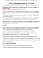
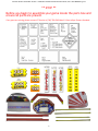
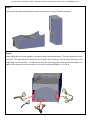
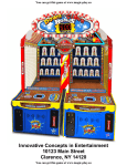
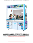
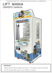
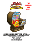
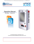
For More Product Information On This + 1600 Other Arcade and Amusment Products, Visit : www.BMIGaming.com
Innovative Concepts in Entertainment
10123 Main Street
Clarence, NY 14120
1
For More Product Information On This + 1600 Other Arcade and Amusment Products, Visit : www.BMIGaming.com
Table of Contents
Safety, Warnings, and Power Requirements
Parts Verification
Cabinet Assembly
Game Controls and Meters
Programming
Bonus Suggestions
Error Codes
4
5
6
20
21
23
24
Service
Ball gate assembly
Displays
Sensors
Power Supplies
Notes
25
29
30
31
32
Warranty
33
Rev B
2/7/2014
3
For More Product Information On This + 1600 Other Arcade and Amusment Products, Visit : www.BMIGaming.com
SAFETY AND WARNINGS BEFORE YOU BEGIN
WARNING: WHEN INSTALLING THIS GAME, A GROUNDED A.C. RECEPTACLE MUST BE USED. FAILURE TO DO SO COULD RESULT IN INJURY TO YOURSELF OR OTHERS. FAILURE TO USE A
GROUNDED RECEPTACLE COULD ALSO CAUSE IMPROPER GAME OPERATION, OR DAMAGE TO
THE ELECTRONICS.
NOTE: THIS GAME IS INTENDED FOR INDOOR USE ONLY.
DO NOT DEFEAT OR REMOVE THE GROUNDING PRONG ON THE POWER CORD FOR THE SAME
REASON AS GIVEN ABOVE. USING AN IMPROPERLY GROUNDED GAME COULD VOID YOUR WARRANTY.
HAVE A QUALIFIED ELECTRICIAN CHECK YOUR A.C. RECEPTACLE TO BE SURE THE GROUND IS
FUNCTIONING PROPERLY.
THIS GAME IS DESIGNED TO DISSIPATE STATIC ELECTRICITY THROUGH THE GROUNDING PLANE
OF THE GAME. IF THE A.C. GROUND DOES NOT WORK, THE GAME COULD DISCHARGE STATIC
ELECTRICITY THROUGH THE GAME CIRCUITRY, WHICH COULD CAUSE DAMAGE.
THE POWER SUPPLY IS NOT VOLTAGE ADJUSTABLE. TO OPERATE THE GAME AT VOLTAGES OTHER THAN THOSE IT WAS DESIGNED FOR. PLEASE CONTACT OUR SERVICE DEPARTMENT FOR
VOLTAGE CONVERSION INFORMATION.
WARNING
DO NOT remove any of the components on the main board (e.g. compact flash and eproms) while
the game is powered on. This may cause permanent damage to the parts and the main board. Removing any main board component part while powered on will void the warranty.
ALWAYS REMOVE POWER TO THE GAME, BEFORE ATTEMPTING ANY SERVICE,
UNLESS NEEDED FOR SPECIFIC TESTING. FAILURE TO OBSERVE THIS PRECAUTION
COULD RESULT IN SERIOUS INJURY TO YOURSELF OR OTHERS.
THIS GAME IS NOT SUITABLE FOR INSTALLATION IN AN AREA WHERE A WATER JET COULD BE USED.
This appliance is not intended for use by persons (including children) with reduced physical, sensory or mental
capabilities, or lack of experience and knowledge, unless they have been given supervision or instruction concerning use of the appliance by a person responsible for their safety. Children should be supervised to ensure that
they do not play with the appliance.
AC Power Information
The value of the fuse for 120 volt users is 2.5 AMPS at 250Volt type slow blow.
The value of the fuse for 230 volt users is also 2.5 AMPS at 250Volt type slow blow.
4
For More Product Information On This + 1600 Other Arcade and Amusment Products, Visit : www.BMIGaming.com
** STOP **
Before you begin to assemble your game locate the parts box and
ensure all parts are present.
If any parts are missing please contact ICE Service at (716) 759-0360 Mon-Fri 9am to 6pm Eastern Standard.
5
For More Product Information On This + 1600 Other Arcade and Amusment Products, Visit : www.BMIGaming.com
Step 1:
Position the front cabinet and the back cabinet leaving room to connect the wire harnesses.
Step 2:
Before sliding the two halves together, you need to plug in the wire harnesses. There are three sets of wire
harnesses. The right side of the cabinet has three cables, two of which are colored coded. Blue goes in the
middle plug, red to the bottom. The left side has only one color plug, green, which goes in the middle. The
middle of the cabinet has three connectors on a small circuit board labeled, J4, J5, and J6.
6
For More Product Information On This + 1600 Other Arcade and Amusment Products, Visit : www.BMIGaming.com
Step 3:
Slide the two halves together and lock the cabinets using the included lock tool. Lock the cabinet on both
sides.
Step 4:
Remove the ball gate cover using an Allen wrench. The long 4” bolts go in the back while the 1¼” bolts go in
the front. Set hardware and wood cover aside.
¼-20 x 1 1/4
¼-20 x 4
7
For More Product Information On This + 1600 Other Arcade and Amusment Products, Visit : www.BMIGaming.com
Step 5:
Attach the right cage using ¼-20 x Joint Connectors on the outside and ¼-20 7/8” bolts on the inside. There
locations are shown below. The front top bolt is 5/8, not 7/8. See note below!!
Repeat for the left cage.
1/4-20x5/8 bolt here only!
Step 6:
Position the upper brace and attach to the cage sides as shown. Use a ¼-20 7/8” bolt to attach the upper
brace to the cage.
8
For More Product Information On This + 1600 Other Arcade and Amusment Products, Visit : www.BMIGaming.com
Step 7:
The long braces attach to the back of the cabinet. The short braces attach to the front of the cabinet. Use ¼20 7/8 bolts to attach arms to cabinet. See below for attaching the cheat sensor to the center.
** Caution: Support Arms can swing and cause injury when not fully attached. **
Short brace
Short brace
Long brace
Long brace
**Note ** Attach the upper braces first using
1/4-20 x 1 1/2” bolt and 1/4-20 keep nut.
Then side the bracket for the cheat sensor on
the bolt and attach with 1/4-20 nylock nut.
The wire harness attaches to the upper brace
with a tie wrap, down the right side to the
front of the cage, down the cage front and
into the wire access hole shown in step 9b. It
connects to the main board shown.
Front
9
For More Product Information On This + 1600 Other Arcade and Amusment Products, Visit : www.BMIGaming.com
Step 8:
Attach the bonus sign to the top of the cabinet using four ¼-20 7/8 bolts and washers as shown. Plug the
sign harness through the back. Attach the two harness on the right and one on the left.
Step 9a: **STOP ** if installing two games with Mega Marquee skip to step 10
If you are going to use the Mega bonus sign do not install this sign. Otherwise, remove the eight screws
holding the sign together. Put the sign and hardware aside.
10
For More Product Information On This + 1600 Other Arcade and Amusment Products, Visit : www.BMIGaming.com
Step 9b:
Located inside the cabinet you will find the cable attached to the upper side of the cabinet. Remove the
bolts holding the control panel so you can slide the panel to expose the access hole that the marquee wire
will travel through. Route the wire through the cage and up to the sign. Attach with wire ties.
Step 9c:
Connect the wire harness before attaching the sign. Use two ¼-20 kep nuts to attach the sign to the upper
support bar. The bolts are already present. Reattach the sign with the hardware you put aside. Install only
in the bottom hole.
11
For More Product Information On This + 1600 Other Arcade and Amusment Products, Visit : www.BMIGaming.com
Step 10:
Attach the left and right plastic front covers using 1/4-20 2¾” bolts. Do not install any bolts at the bottom.
Do not over tighten. The rebound guard attaches there. See step 14 if installing two games together. Do
not install the plastic front cover on the sides that will be together.
Step 11
Attach the rebound guard from the back of the cages. The ¼-20 3½” bolts go through the front and the
washers plus kep nuts in the back. Do not install at this time if you are joining two cabinets together and installing a Mega marquee.
12
For More Product Information On This + 1600 Other Arcade and Amusment Products, Visit : www.BMIGaming.com
Step 12
Attach on the right side of the game the plaque that states “pure skill game” using square bit screws and
attach your choice of coinage on the left side of the game using square bit screws.
NOTE: Do not install plaques on the sides that will be joined together at this time.
Step 13 *** This is the last step if not installing two games with Mega Marquee ***
Position the canopy onto the top of the cabinet. Lift the side slightly on the canopy to expose the mounting
flap with pre made holes. Front of cabinet has reinforced holes for front mount. Use the self tap screws to
attach the canopy to the cabinet. Do not screw through the front of the canopy!
** Note **
20 Balls are recommended to be in play at anytime.
13
For More Product Information On This + 1600 Other Arcade and Amusment Products, Visit : www.BMIGaming.com
Step 14: ** STOP ** Mega Marquee Install Steps Continued. See Prior steps.
Position the two games together. You should only have the plastic front covers installed on the outer sides
of the cabinet. The inner plastic front sides will not be used.
Step 15
Install the cabinet spacers on the insides of the two cabinets using 1½” drywall screws. Mounting holes are
predrilled in the spacers.
14
For More Product Information On This + 1600 Other Arcade and Amusment Products, Visit : www.BMIGaming.com
Step 16
If your pole has the extended support wings removed, locate the 8 1/4-20 x 1” bolts from the parts bin and
lock washers. Attached the extended wings following the diagrams below.
Step 17
Locate both the Center pole of your Mega Marquee and the top marquee sign. Position the center pole into
the top bracket. Use 8 xx bolts and lock washers to secure the center pole to the upper sign.
X’s 1
X’s 8
X’s 1
15
For More Product Information On This + 1600 Other Arcade and Amusment Products, Visit : www.BMIGaming.com
Step 18
Attach the Large Red center plastic to the center pole.
Step 19
Slide the two cabinets together, tilt the Mega Marquee back a little, and insert the bottom of the Mega Marquee into the cabinet slots as shown.
16
For More Product Information On This + 1600 Other Arcade and Amusment Products, Visit : www.BMIGaming.com
Step 20
Insert the canopy flaps into the top slots of the marquee. Attach the marquee to the cabinet cages using ¼20 2¾” bolts. Attach the rebound guards at this time. See step 11 for instructions.
Step 21
Attach the Front trim and “Pure Skill Plaque”
17
For More Product Information On This + 1600 Other Arcade and Amusment Products, Visit : www.BMIGaming.com
Step 22
Attach the small red plastic trim pieces with one 1¼” screw through the front.
Step 23
Remove the graphic front by first removing the two ¼-20 1¼” bolts on either side of the stars. Attach the
sign using 4 ¼-20x1¼” kep nuts.
18
For More Product Information On This + 1600 Other Arcade and Amusment Products, Visit : www.BMIGaming.com
Final Step:
Attach the data cable at the back of the Marquee. Tuck the cable under the canopy on the left side of the
game and down the front side of the cage. Do not run it down on the right cabinet. There is no wire access hole. It will be necessary to remove the front screw if attached. It will be easier to slide the control
panel out of the way by removing the mounting bolts. This will allow easier access to the wire access hole.
See Step 9b. On the main board are two phone style connectors. You can plug in either of them. Now run
the AC cord from the back of the marquee to a wall outlet. Refer to step 11 to install the rebound guards
on both games.
A/C Cord
Data
** Note **
20 Balls are recommended to be in play at anytime.
19
For More Product Information On This + 1600 Other Arcade and Amusment Products, Visit : www.BMIGaming.com
Game controls and Meters
Located on the center door is the operators control panel. There
you can quickly adjust the volume of the game by pressing the “UP”
and “DOWN” push buttons. You can view how many coin pulses the
has seen and how many tickets it had paid out.
To adjust the game’s programming, press the “PROG” button to enter programming. The “SELECT” push button will cycle through the
different options. Pushing the “UP” push button will increase the
options’ value while pressing the “DOWN” push button will decrease
the options’ value.
It is recommended to use our suggestive settings when configuring
your game. Please review the next few pages before determining
your settings.
20
For More Product Information On This + 1600 Other Arcade and Amusment Products, Visit : www.BMIGaming.com
Programming Options for Down Da Clown
Seconds Display Blank
Value
Option
0
Game Volume
Option Number
Default
Min
Max
Inc
Short Description
5
0
7
1
Game Volume
0
7
1
Music Volume
0
10
1
Cost of Game
0
10
1
# of Coin 1’s
This option adjusts the general game sounds.
1
Music Volume
3
This option adjusts the music in the game and attract mode.
2
Coin 1
1
How many pulses to start your game.
3
Coin 2
1
This pulse is equal to the cost of the game. Use as a multiplier for credits.
4
DBV
4
0
10
1
# of Coin 1’s
This pulse is equal to the cost of the game. Use as a multiplier for credits.
5
Attract Time
0
0
90
1
Attract time
This options determines how much time to be idle between its attract time.
6
Red Seconds
3
1
10
1
Seconds between Red lite Attempts
During the game you can determine how much time to wait before lighting a clown red for the double point feature.
7
Bonus Score
500
10
999
10
Bonus Target Score
How much a player must score before achieving the bonus cloud.
8
Bonus Tickets
100
0
How many tickets you win when you win the bonus cloud.
999
25
Bonus Ticket Value
9
Game Time
30
1
Time for Game Play
20
10
How long the game lasts.
10
This option is for factory use only. You cannot change it.
11
This option is for factory use only. You cannot change it.
Options continued on next page…..
21
For More Product Information On This + 1600 Other Arcade and Amusment Products, Visit : www.BMIGaming.com
12
Red Zone Tickets
1
0
20
1
JFP Tickets
Sets the amount of tickets to win when 0 to 40 points are scored. See Score chart below. Also is used for giving tickets
just for playing.
13
Orange Tickets
2
1
250
1
Tickets for Zone
Sets the amount of tickets to win when 50-90 points are scored. See Score chart below.
14
Yellow Tickets
3
1
250
1
Tickets for Zone
Sets the amount of tickets to win when 100-190 points are scored. See Score chart below.
15
Green Tickets
4
1
250
1
Tickets for Zone
Sets the amount of tickets to win when 200-290 points are scored. See Score chart below.
16
Blue Tickets
5
1
250
1
Tickets for Zone
Sets the amount of tickets to win when 300-390 points are scored. See Score chart below.
17
Indigo Tickets
10
1
250
1
Tickets for Zone
Sets the amount of tickets to win when 400-490 points are scored. See Score chart below.
18
Ticket Multiplier
1
0
2
1
0 = Just for Fun
1 = 1 ticket = 1 ticket
2 = 2 tickets = 1 ticket
This allows you to either turn off tickets and play for a score, pay out normal, or pay 1/2 the amount of tickets owed.
19
Lockup
0
0
1
1
0=Normal Tilt, 1= Lock up game
This option when set to 1 and when the game is tilted (cheat sensor is tripped) will lock up the game until you cycle power.
20
Factory Reset
Setting this option to 1 will cause the game to load factory defaults when power is cycled.
.50¢ Game
$2.00 Game
Suggestive Values
Suggestive Values
.25¢ Game
Suggestive Values
$1.00 Game
Suggestive Values
OPTION 12
OPTION 13
OPTION 14
OPTION 15
OPTION 16
OPTION 17
OPTION 8
OPTION 7
22
For More Product Information On This + 1600 Other Arcade and Amusment Products, Visit : www.BMIGaming.com
23
For More Product Information On This + 1600 Other Arcade and Amusment Products, Visit : www.BMIGaming.com
Error Codes for Down Da Clown
Error 1
Ticket Error
Solution:
Refill Tickets!
Error 2
CF Error ; Compact flash error
Solution:
Reseat Flash card or replace.
Error 3
Ball Gate Error
Solution:
Check for proper ball gate operation. See section “Ball Gate Assembly”
Error 4
Top Motor/Switch Error ; Top Row switch not seen.
Solution:
Check Clown Reset Bracket sensor. See section “Clown Reset Bracket Sensor”
Error 5
Middle Motor/Switch Error ; Middle Row switch not seen.
Solution:
Check Clown Reset Bracket sensor. See section “Clown Reset Bracket Sensor”
Error 6
Bottom Motor/Switch Error ; Bottom Row switch not seen.
Solution:
Check Clown Reset Bracket sensor. See section “Clown Reset Bracket Sensor”
To enter Error display mode, please press the UP push button located on the lower center door when in attract. To exit this mode, repress the UP push button .
24
For More Product Information On This + 1600 Other Arcade and Amusment Products, Visit : www.BMIGaming.com
Ball-gate Assembly
Step 1: Ball-gate Removal
Remove the wood panel ball gate cover as shown.
The cages, canopy, support bars, and rebound have been removed for clarity.
Step 2: Ball-gate Removal
Remove three woodscrews on each side as shown below. Remove these screws on both sides.
Step 3: Ball-gate Removal
Loosen the 5/64 Allen set screw. Lift the ball defectors
25
For More Product Information On This + 1600 Other Arcade and Amusment Products, Visit : www.BMIGaming.com
Step 4: Ball-gate Removal
There are two black wood screws that hold the ball gate assembly to the cabinet. They are shown below. Remove them.
Step 5: Ball-gate Removal
Lift the ball gate straight up and unplug the wire harness before lifting the ball gate assembly out.
26
For More Product Information On This + 1600 Other Arcade and Amusment Products, Visit : www.BMIGaming.com
Step 1: Motor Removal (REMOVE BALLGATE ASSEMBLY BEFORE PROCEEDING)
Flip the ballgate assembly over and remove the four Allen screws and lock washers shown.
Step 2: Motor Removal
Removal the Screw that holds motor shaft to the ball deflector shaft. This screw
has Loctite applied to it and could be difficult to remove.
Step 3: Motor Removal
Step 4: Motor Removal
Loosen the grub screw that holds the motor cam shaft to the
motor. This grub screw also has Loctite applied to it and could
be difficult to loosen. Lift the cam shaft off.
Remove the two screws that hold the motor to the motor
mount.
27
For More Product Information On This + 1600 Other Arcade and Amusment Products, Visit : www.BMIGaming.com
Ball-gate sensors Access
Remove the two screws that hold the gate cam to the Primary Ball gate assembly. Slide the Primary Ball gate assembly out.
Gate Cam
Primary Ball Gate
Ball-gate sensors Operation
There are two magnetic sensors located under the primary ball gate assembly. The primary ball gate assembly has a magnetic
attached underneath so that when the assembly rotates it will pass over one of the two sensors. When the ball gate assembly
moves counter clock-wise, it will pass over the sensor for the closed position and stop the assembly. When the ball gate assembly
rotates clock-wise, it will pass over the sensor for the open position and stop the assembly. Using a volt meter, when the magnet
passes over either of the sensors, that sensor will have no voltage present. When the magnet is not over the sensor it should read
+5 volt of DC power. With the power off on the game, the sensor is normally open.
** WARNING ** Never manually move the Primary Ball Gate assembly as damage will occur to the motor gearbox assembly below.
Gate closed Sensor
Magnetics
Gate open Sensor
Primary Ball Gate
Ball-gate sensors Removal
To remove a sensor, disconnect the two pin connector. Then unscrew the tie-wrap and push the sensor out. To install a replacement sensor, insert the connector from the top through the hole and push firmly down. Attach the wire harness and re-install the
wire tie.
Sensor
Two pin connector
Tie-Wrap
28
For More Product Information On This + 1600 Other Arcade and Amusment Products, Visit : www.BMIGaming.com
Control Panel: Small and Large Display Removal
To access the two display boards remove the bolts marked with
the x. Lift the control panel and unplug the 5 pin Molex plug.
Remove the control panel and flip over.
Small Display:
Remove protective cover.
1
Large Display:
Remove protective cover.
1
Remove plastic standoffs
Disconnect Wire harness and remove.
2
3
Remove plastic standoffs.
Disconnect harnesses and remove.
3
2
29
For More Product Information On This + 1600 Other Arcade and Amusment Products, Visit : www.BMIGaming.com
Clown Reset Bracket Sensor
The Clown reset bracket assembly will stand clowns back up after being knocked down. During game play and when the entire row
is knocked down, the reset bracket assembly’s motor will activate causing the bracket to push the clowns up. Upon one complete
turn the bracket will return to its starting position. A magnet sensor is used to tell the game where the bracket is. If the sensor is
not working the bracket assembly will run one more time and time out.
If the sensor that detects that the clown has been knocked down fails then the Reset Bracket will run on that row every 30 seconds
during its attract mode.
Sensor
Home Position Sensor Replacement
Unplug the two pin sensor harness attached to the bracket. Remove the two wood cabinet screws and remove the BL3033X
block assembly. Install in reverse.
Woodscrews
BL3033X
Unplug Harness
1
2
30
3
For More Product Information On This + 1600 Other Arcade and Amusment Products, Visit : www.BMIGaming.com
Power Supply Access
SUZO HAPP Power Pro
There are two power supplies used in your game. One is a
IA2010 and the other is a UC2010. The UC2010 power unit
supplies +12 volts DC to both the audio circuitry and the LED’s.
The IA2010 power supply supplies the +12 volt DC for the rest
of the cabinet. To access these supplies, open the front center
door.
ADJ
IA2010
Input
95V - 135VAC
Turn clockwise to increase power if low
ON
+12
+12V
Power on status
+ 12 Volts DC - 10 Amps; orange
+ 12 Volts DC - 10 Amps ; orange
GND
DC Ground - Black
GND
DC Ground - Black
GND
DC Ground - Black
FG
AC Earth Ground - Green with Yellow
AC
AC Line - Black or Brown
3.2A
AC
AC Neutral - White or Blue
Checking DC Voltages
Volt test with the volt meter set to DC voltage. The +12 output can be adjusted by turning
the adjustment screw of the power supply. Adjust to as close to +12 as possible. Increasing the +12. The voltage range can be plus or minus 5%.
Turn to DC voltage check
Positive Probe:
Connect to +12V on power supply
Ground Probe:
Connect to GND on power supply
31
For More Product Information On This + 1600 Other Arcade and Amusment Products, Visit : www.BMIGaming.com
** NOTES
1) Located on the main board are left and right audio connections. The front audio connection supplies General game sounds
while the back connection supplies the clown voices.
2) Proper Startup sequence is upon power up the game will show the revision of software it is running on the score display. Then
the display will show 200.
3) When troubleshooting LED color issues, what as the colors changes during attract. As they change they will go from color to
color. At some point it will show the primary colors. They are Red, Green, and Blue. Ensure all colors are present and if one
color is missing, look for bad connections from the main board, through the resistor board, and finally to the LED’s on the
shelf. Refer to the schematic insert for more information.
32
For More Product Information On This + 1600 Other Arcade and Amusment Products, Visit : www.BMIGaming.com
WARRANTY POLICY
I.C.E. Inc warrants all components in new machines to be free of defects in materials and workmanship for the
period listed below:
■ 180 days on Main PCB’s, Computers & Motors
■ 1 year on all LCD monitor panels
■ 90 days on all other electronic and mechanical components
■ 30 days on all I.C.E. repairs and parts purchases
I.C.E. Inc shall not be obligated to furnish a warranty request under the following conditions:
■ Equipment or parts have failed through normal wear and tear
■ Equipment has been subjected to unwarranted stress, abuse or neglect
■ Equipment has been damaged as a result of arbitrary repair/modification
Products will only be covered under warranty by obtaining an I.C.E. authorized RMA #. To obtain an RMA #
please provide I.C.E. tech support with the game serial # or original I.C.E. invoice # and a detailed description
of the failure or fault symptoms.
I.C.E. Inc will assume no liability whatsoever for costs associated with labor or travel time to replace defective
parts. All defective warranty covered components will be replaced with new or factory refurbished components equal to OEM specifications.
I.C.E. Inc will cover domestic UPS ground, or comparable shipping costs during the warranty period. International or expedited shipments are available for an additional charge. To obtain credit defective parts must be
returned to I.C.E. Inc, at the customer’s expense, within 30 days. After 30 days a 15% re-stocking fee will apply to all returns.
ICE distributors are independent, privately owned and operated. In their judgment, they may sell parts and/or
accessories other than those manufactured by I.C.E. Inc. We cannot be responsible for the quality, suitability
or safety of any non-I.C.E. part or modification (including labor) that is performed by such a distributor.
Innovative Concepts in Entertainment
10123 Main St.
Clarence, NY 14031
Phone #: (716) - 759 – 0360
Fax #: (716) – 759 – 0884
www.icegame.com
33