1
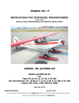
Airglas, Inc. ® Amphibious hydraulic system addendum to Instructions for Continued Airworthiness Including Installation, Maintenance and Service Instructions MANUAL NO. GLH3000-105-AHSA MODEL GLH3000 Ski Kit Actuated by Wipaire, Inc. Amphibious Float Hydraulic System Cage Code 17564 Airglas Inc.® MANUAL REVISION C April 23, 2015 THIS MANUAL INCLUDES INFORMATION PROPRIETARY TO Airglas, Inc. AND SHALL NOT BE USED TO MANUFACTURE OR REPRODUCE ANY PART OR ASSEMBLY WITHOUT THE PRIOR WRITTEN PERMISSION OF Airglas, Inc. Airglas, Inc. Manual # GLH3000-105-AHSA Record of Revision REV REV DATE LEVEL Original Affected BY EXPLANATION OF REVISION Pages 3/21/2013 - Original Document Clifford D. Belleau A 10/3/2014 3, 12 Clifford D. Belleau Added Airworthiness limitations, revised section 9. B 3/3/2015 12 Clifford D. Belleau Revised section 9 C 4/23/2015 12 Clifford D. Belleau Revised section 9 Distribution of Changes A new copy of the revised manual or affected pages will be maintained on the Airglas, Inc. website. To be eligible for installation using this manual the fuselage hydraulic system must have been installed in accordance with the installation drawings and revision level below or a prior revision level. Aircraft Model Amphibious Float Wipaire Amphibious Revision Level STC/TCDS Number Float Hydraulic System Installation Drawing Piper PA-18 Series SA00713CH 10D1-6022 Rev. C Piper PA-12 Series SA00901CH 10D1-6027 Rev. Original Aviat A-1 Series SA00637CH 10D1-6066 Rev. F Cub Crafters CC18- S00006SE TC10400 Rev. C 180 Series Cessna 170A, 170B SA00804CH 10D1-6391 Rev. Original Cessna 180 Series SA01320CH 12D1-7304 Rev. B 2|Page MANUAL REVISION C April 23, 2015 THIS MANUAL INCLUDES INFORMATION PROPRIETARY TO Airglas, Inc. AND SHALL NOT BE USED TO MANUFACTURE OR REPRODUCE ANY PART OR ASSEMBLY WITHOUT THE PRIOR WRITTEN PERMISSION OF Airglas, Inc. Airglas, Inc. Manual # GLH3000-105-AHSA Sections Page 1.0 Introduction and Description 4 2.0 Placards and Markings 5-6 3.0 Installation-Ski Attachment 7-8 4.0 Control and Operation 8-9 5.0 Servicing Information 9 6.0 Instructions for Continued Airworthiness 10 7.0 Specifications 10 8.0 Trouble Shooting 11 9.0 Drawings and Diagrams 12 10.0 Engineering Changes and Amendments 13 Airworthiness Limitations "The Airworthiness Limitations section is FAA approved and specifies maintenance required under Sections 43.16 and 91.403 of the Federal Aviation Regulations unless an alternative program has been FAA approved." Limitations: Currently there are no components of the GLH3000 Wheel Ski Kit that have a time limited mandatory service interval. 3|Page MANUAL REVISION C April 23, 2015 THIS MANUAL INCLUDES INFORMATION PROPRIETARY TO Airglas, Inc. AND SHALL NOT BE USED TO MANUFACTURE OR REPRODUCE ANY PART OR ASSEMBLY WITHOUT THE PRIOR WRITTEN PERMISSION OF Airglas, Inc. Airglas, Inc. Manual # GLH3000-105-AHSA 1.0 Introduction & Description Introduction: This manual is an addendum to manual no. GLH3000-105. This manual provides installation instructions specific to the alteration of the Wipaire, Inc. hydraulic system to allow it to safely and reliably actuate the hydraulic cylinders of the GLH3000 hydraulic wheel skis installed under STC SA02360AK. For installation, inspection, and repairs not covered in this manual refer to manual no. GLH3000-105 for the ski installation, and Wipaire, Inc. model 2100/2350 float Service Manual no. 1002549 for the fuselage hydraulic installation. Description: The alteration of the Wipaire, Inc. amphibious float hydraulic system to actuate the GLH3000 ski kit requires the following operations: 1. Remove the two each amphibious float hoses p/n 10B2-6169-11 (21A09000-205) and 10B26169-11 (21A09000-206) from the two AN827-4D crosses located under the cockpit floor. (REF. Wipaire, Inc. Drawing No. 10D1-6022) (CC18-180 installation uses AN834-4D bulkhead fittings thru fuselage belly panel, disconnect above hose part numbers at those fittings) 2. Install four each shop fabricated Stratoflex 111-4 hoses between the AN827-4D crosses and the ski hydraulic cylinders. (CC18-180 installation uses AN834-4D bulkhead fittings thru fuselage belly panel, connect shop fabricated hoses to those fittings) 3. Remove the four each blue and green indicator lights from the gear selector. 4. Install blanking cover plate P/N 10B3817 (ROUND SELECTORS) or 10B3818 (RECTANGULAR SELECTORS). 5. Install placards as indicated in Airglas, Inc. AFMS AI-12-1FM. 6. Pull the gear advisory circuit breaker and secure with tie-wrap. Label circuit breaker “DISABLED". 7. Compliance with Wipaire, Inc. Service Letter #48 is recommended for consistent operation. Note: All hardware in this kit shall be installed and torqued IAW AC 43.13-1B Chapter 7, Par 7-40, Table7-1 and table 7-2. Note: Hoist the aircraft and remove the floats in accordance with Wipaire 1002549 Rev. E or current revision. Install landing gear in accordance with the table below: Piper Aircraft AC 43.13-1B Aviat A-1C aircraft Aviat ICA document 70192-006 Aviat A-1 aircraft Aviat ICA document 70192-002 Aviat A-1A aircraft Aviat ICA document 70192-002 Aviat A-1B aircraft Aviat ICA document 70192-004D Cessna 170 Aircraft AC 43.13-1B and D138-13 Cessna 180 Aircraft AC 43.13-1B and D138-13 4|Page MANUAL REVISION C April 23, 2015 THIS MANUAL INCLUDES INFORMATION PROPRIETARY TO Airglas, Inc. AND SHALL NOT BE USED TO MANUFACTURE OR REPRODUCE ANY PART OR ASSEMBLY WITHOUT THE PRIOR WRITTEN PERMISSION OF Airglas, Inc. Airglas, Inc. Manual # GLH3000-105-AHSA 2.0 Placards and Markings PLACARDS The following information must be displayed in the form of composite or individual placards in addition to those specified in the basic handbook. Markings and Placards: The airspeed indicator is marked as follows: A.) o The red radial line is located at 138 MPH. DO NOT EXCEED 138 MPH IAS WITH AIRGLAS GLH3000 SKIS INSTALLED Place Airspeed Restriction Placard on instrument panel immediately adjacent to Airspeed Indicator and in full view of pilot. (All Models, except Cessna 180 series) DO NOT EXCEED 172 MPH IAS WITH AIRGLAS GLH3000 SKIS INSTALLED Place Airspeed Restriction Placard on instrument panel immediately adjacent to Airspeed Indicator and in full view of pilot. (Cessna 180 series) ONLY NORMAL CATEGORY OPERATIONS APPROVED, SPINS ARE PROHIBITED. Place Operations Placard on instrument panel in full view of pilot. (All Models) CAUTION- IT IS POSSIBLE TO EXCEED THE FORWARD CG LIMITAION WITH AIRGLAS SKIS INSTALLED AND MINIMUM FUEL. OPERATIONS OUTSIDE THE CG LIMITATIONS ARE PROHIBITED. Place Placard on instrument in full view of pilot. (Aviat A-1 series, 170A, 170B, 180 Series) MAXIMUM WEIGHT LIMITED TO 2000 LBS. WITH AIRGLAS GLH3000 SKIS INSTALLED Place Placard on instrument in full view of pilot. (A-1B, A-1C-180 and A-1C-200) CAUTION- IT IS POSSIBLE TO EXCEED THE MAXIMUM WEIGHT LIMITAION WITH AIRGLAS SKIS INSTALLED AND ALL SEATS OCCUPIED. OPERATIONS OUTSIDE THE MAXIMUM WEIGHT LIMITATIONS ARE PROHIBITED. Place Placard on instrument in full view of pilot. (170A, 170B, 180 series) 5|Page MANUAL REVISION C April 23, 2015 THIS MANUAL INCLUDES INFORMATION PROPRIETARY TO Airglas, Inc. AND SHALL NOT BE USED TO MANUFACTURE OR REPRODUCE ANY PART OR ASSEMBLY WITHOUT THE PRIOR WRITTEN PERMISSION OF Airglas, Inc. Airglas, Inc. Manual # GLH3000-105-AHSA PLACARDS-Continued Adjacent to the gear selector knob: WHEEL SELECTOR PUMP ON (RED LIGHT) UP SNOW DOWN LAND In full view of the pilot: EMERGENCY 1. 2. 3. 4. GEAR EXTENSION Pull the landing gear pump circuit breaker. Move landing gear position switch to desired position. Select the desired position on the Emergency Gear Selector. Manually pump until the desired tire position is obtained and there is significant force on the pump handle. (Approximately 80 strokes of the hand pump.) 5. Visually confirm the skis are in the desired configuration for the intended landing. On the emergency gear selector knob: UP NEUTRAL DOWN 6|Page MANUAL REVISION C April 23, 2015 THIS MANUAL INCLUDES INFORMATION PROPRIETARY TO Airglas, Inc. AND SHALL NOT BE USED TO MANUFACTURE OR REPRODUCE ANY PART OR ASSEMBLY WITHOUT THE PRIOR WRITTEN PERMISSION OF Airglas, Inc. Airglas, Inc. Manual # GLH3000-105-AHSA 3.0 Installation For installation of the skis refer to Manual No. GLH3000-105. Disregard the portions of Section 3.0 regarding the Cockpit Controls, and Hydraulic Pump & Line Routing. Follow the sections below to adapt the existing Wipaire, Inc. amphibious hydraulic system to function correctly with the GLH3000 hydraulic wheel ski kit. Refer to drawings: GLH3000-6 Sheet 2 Hydraulic System (Steel Tube Fuselages) GLH3000-170-HYD Sheet 2 Hydraulic System Installation on Cessna 170,180 1. 2. 3. 4. 5. 6. 7. COCKPIT CONTROLS Turn off master switch and disconnect positive battery terminal. Tag battery cable ”Disconnected for maintenance”. Determine if the aircraft is equipped with a round gear control selector or square gear control selector. For a round selector use a Wipaire P/N 10B3817 cover, for a rectangular selector use a Wipaire P/N 10B3818 cover. Remove the 8 gear lights from the selector face (4 blue, 4 green). Pinch the bulb lens and gently shake and pull. (Do not twist, as pins will be broken off the back of the bulbs.) Retain bulbs for reinstallation. Remove knob on gear selector switch. (knob screws on with right hand thread) Remove the three screws holding the selector into the panel. Leave the upper right screw in place for the round selectors (upper left on rectangular selectors). Position the cover plate P/N 10B3817 (P/N 10B3818 for rectangular selector) over the existing selector. Reinstall the three screws and reinstall the selector knob. UP SNOW PUMP ON WHEEL SELECTOR DOWN LAND UP SNOW WHEEL SELECTOR PUMP ON DOWN LAND 10B3818 RECTANGULAR COVER (GEAR CONTROL) 10B3817 ROUND COVER (GEAR CONTROL) 7|Page MANUAL REVISION C April 23, 2015 THIS MANUAL INCLUDES INFORMATION PROPRIETARY TO Airglas, Inc. AND SHALL NOT BE USED TO MANUFACTURE OR REPRODUCE ANY PART OR ASSEMBLY WITHOUT THE PRIOR WRITTEN PERMISSION OF Airglas, Inc. Airglas, Inc. Manual # GLH3000-105-AHSA HYDRAULIC PUMP & LINE ROUTING 1. Remove the two each 10B26169-11 and 10B2-6169-10 hoses from the AN827-4D crosses located under the floor boards. (location may vary in different aircraft). Cap the crosses using AN929-4 caps, plug the hoses using AN806-4D plugs. (CC18-180 installation uses AN834-4D bulkhead fittings thru fuselage belly panel, disconnect above hose part numbers at those fittings) 1A. Cessna 170A and 170B aircraft: Remove the four each 10B26169-20 hoses from the AN8334D bulkhead fittings located on the fuselage belly. Cap the fittings using AN929-4 caps, plug the hoses using AN806-4D plugs. 2. Fabricate four each hoses using Stratoflex 111-4 hose and Stratoflex 300-4S fittings (646-4S 45 and 649-4S 90 fittings if required) in accordance with AC43.13-2B paragraph 9-30 d.(2). 3. Remove the AN929-4 caps from the AN827-4D crosses and connect the hoses. Connect the lower end of the hoses to the ski hydraulic rams. Route and secure the hoses in accordance with AC43.13-2B paragraph 9-30 d.(3). Connect the forward end of the hydraulic ram to the “UP” cross. Connect the aft end of the hydraulic ram to the “DOWN” cross. (CC18-180 installation uses AN834-4D bulkhead fittings thru fuselage belly panel, connect shop fabricated hoses to those fittings) 4. Hydraulic lines must be routed and secured so that they do not interfere with flight controls and are not able to chafe. 5. Service hydraulic pump reservoir in accordance with section 5 of this manual. 6. Clean all spilled hydraulic fluid. 7. Reconnect battery. 4.0 Control and Operation Control and Operation Information: The door for the GLH3000 Ski is actuated by the electric/hydraulic pump (preferred) or a manually operated hand pump in the cockpit. The electric/hydraulic pump is controlled via a 2 position toggle switch and indicator lights that are located on the instrument panel. 1. When the switch is lifted up, the cylinder will extend and slide the door under the tire. A red indicator light (Pump-On) will illuminate showing the ski position has been selected and the pump is cycling. When the pump reaches a pre-set pressure of 700 PSI the “Pump-On” light will extinguish, indicating the pump has shut off. Visual confirmation of the actual ski position is required. If the desired position has not been reached, select “UP” on the manual selector on the hand pump and pump until the skis reach the desired position. 2. When the switch is pressed down, the door will retract and expose the tire. A red indicator light (Pump-On) will illuminate showing the wheel position has been selected. When the pump reaches a pre-set pressure of 700 PSI the “Pump-On” light will extinguish, indicating the pump has shut off. Visual confirmation of the actual ski position is required. If the desired position 8|Page MANUAL REVISION C April 23, 2015 THIS MANUAL INCLUDES INFORMATION PROPRIETARY TO Airglas, Inc. AND SHALL NOT BE USED TO MANUFACTURE OR REPRODUCE ANY PART OR ASSEMBLY WITHOUT THE PRIOR WRITTEN PERMISSION OF Airglas, Inc. Airglas, Inc. Manual # GLH3000-105-AHSA has not been reached, select “DOWN” on the manual selector on the hand pump and pump until the skis reach the desired position. Note: If the pressure switch in the electro-hydraulic pump system should fail the pump will continue to run after the skis are in the desired position. The power can be manually turned off by pulling the pump circuit breaker. The skis can still be operated using the power pack by turning the power back on (pushing the circuit breaker in) and selecting the next desired position and again manually turning off the power if necessary. The faulty pressure switch should be repaired as soon as possible. 5.0 Servicing Information Mechanical System – For servicing of the skis refer to Manual No. GLH3000-105. Hydraulic System – The hydraulic system supplied uses an Electric/Hydraulic Pump, to pump fluid to a hydraulic actuating cylinder mounted on the ski (a hand pump is provided for emergency back-up). Refer to the appropriate Wipaire service manual for service and repairs to the fuselage hydraulic system. Refer to Airglas, Inc. Manual No. GLH3000-105, for service and repairs to the ski hydraulic components. Air is bled from the hydraulic system by cycling the skis several times. The electric pump is self bleeding. MIL-H-5606 or compatible hydraulic fluid is required for filling and servicing the system. The fluid level should not be lower than 1/3 full in the reservoir, and should only be serviced with the cylinders fully retracted to prevent overflow (tires protruding from the skis). 9|Page MANUAL REVISION C April 23, 2015 THIS MANUAL INCLUDES INFORMATION PROPRIETARY TO Airglas, Inc. AND SHALL NOT BE USED TO MANUFACTURE OR REPRODUCE ANY PART OR ASSEMBLY WITHOUT THE PRIOR WRITTEN PERMISSION OF Airglas, Inc. Airglas, Inc. Manual # GLH3000-105-AHSA 6.0 Instructions for Continued Airworthiness MAINTENANCE AND GROUND HANDLING RESTRICTIONS For maintenance and ground handling restrictions, refer to Manual No. GLH3000-105. 7.0 Ski Specifications Ski Specifications are as follows: Length= Width= Height= Weight= Surface Area in2= Center of Gravity= GLH3000 74” 20” 3.625” TO TOP OF TUNNEL 45 lbs. 1435 GLH3000-SG 74” 20” 3.625” TO TOP OF TUNNEL 62 lbs. 1435 8” FWD OF AXLE 7.25” FWD OF AXLE 10 | P a g e MANUAL REVISION C April 23, 2015 THIS MANUAL INCLUDES INFORMATION PROPRIETARY TO Airglas, Inc. AND SHALL NOT BE USED TO MANUFACTURE OR REPRODUCE ANY PART OR ASSEMBLY WITHOUT THE PRIOR WRITTEN PERMISSION OF Airglas, Inc. Airglas, Inc. Manual # GLH3000-105-AHSA 8.0 Trouble Shooting Problem: “Pump On” light fails to go out. Correction: Confirm pressure switches are functioning. Problem: Skis do not cycle smoothly, or have pulsing or incomplete actuation. Correction: Hydraulic Fluid (MIL-H-5606) level is too low. Problem: Hydraulic fluid overflows from reservoir when skis are retracted. Correction: Reservoir filled while skis were deployed. (Always fill with skis retracted) Problem: Skis try to dive in flight. Correction: Skis are rigged at too low angle of attack, or bungees are deteriorated. Problem: Tires scuff on cut-out in ski. Correction: Confirm tire pressures are 20 psi minimum, adjust rod-ends and/or shim washers. Problem: Pump fails to run until manual selector is cycled thru one or both ski positions. Correction: Confirm Wipaire Service Letter #48 is complied with. If complied with, check that accumulator hoses have not filled with hydraulic fluid. 11 | P a g e MANUAL REVISION C April 23, 2015 THIS MANUAL INCLUDES INFORMATION PROPRIETARY TO Airglas, Inc. AND SHALL NOT BE USED TO MANUFACTURE OR REPRODUCE ANY PART OR ASSEMBLY WITHOUT THE PRIOR WRITTEN PERMISSION OF Airglas, Inc. Airglas, Inc. Manual # GLH3000-105-AHSA 9.0 Drawings and Diagrams GLH3000 Installation Drawings Instructions for Continued Airworthiness Including Installation, Maintenance and Service Instructions Amphibious hydraulic system addendum to Instructions for Continued Airworthiness Including Installation, Maintenance and Service Instructions Ski Installation Piper PA-18 Ski Installation Piper PA-18 Ski Installation Piper PA-18 GLH3000 Ski Installation A-1 Series GLH3000 Ski Installation A-1 Series GLH3000 Ski Installation A-1 Series GLH300 Ski Installation on Cessna 170, 180 Hydraulic System Steel Tube Fuselages GLH3000 Hydraulic Installation on Cessna 170, 180 Electrical Schematic GLH3000-105 Rev G 18 pages March 3, 2015 GLH3000-105-AHSA Rev C 12 pages April 23, 2015 GLH3000-1-PA18 GLH3000-1-PA18 GLH3000-1-PA18 GLH3000-1-A1 GLH3000-1-A1 GLH3000-1-A1 Rev C Rev C Rev D Rev B Rev A Rev B GLH3000-170 Rev A Sheet 1 of 3 Sheet 2of 3 Sheet 3 of 3 Sheet 1 of 3 Sheet 2 of 3 Sheet 3 of 3 Sheets 1 thru 4 9 Nov 2011 25 Jun 2012 23 March 2015 7 Sept. 2012 9 Nov 2011 23 April 2015 May 8, 2013 GLH3000-6 Rev A Sheets 1 & 2 Oct. 10, 2014 GLH3000-170-HYD Rev C Sheets 1 & 2 Oct. 10, 2014 GLH3000-7 Rev E Sheet 1 of 1 August 9, 2013 10.0 Engineering Changes and Amendments In the event that a change or amendment is made to the design, components, or procedures contained within this manual or the STC that affect the airworthiness of the ski installation; Airglas, Inc. will notify the recorded owner in writing of the affected element(s) and provide the necessary data for compliance. — END — 12 | P a g e MANUAL REVISION C April 23, 2015 THIS MANUAL INCLUDES INFORMATION PROPRIETARY TO Airglas, Inc. AND SHALL NOT BE USED TO MANUFACTURE OR REPRODUCE ANY PART OR ASSEMBLY WITHOUT THE PRIOR WRITTEN PERMISSION OF Airglas, Inc.