1
Lotus Service Notes
6.
Section PL
Refit in reverse order to removal, ensuring that the sealing foam between the unit and baffle panel and on
the chassis scuttle is present and in good condition. Secure by re-rivetting the retaining bracket.
PL.13 - REFRIGERANT PIPES
The main feed and return (high pressure liquid and low pressure suction) lines to the compressor take the
form of aluminium pipes routed along the outside of the RH chassis rail, such that removal of the body sill panel
is required for access to the pipes. Replacement of the pipes is unlikely to be necessary other than as a result
of accident damage, in which case the body sill will be replaced in accordance with Service Notes Section BQ.
PL.14 - AIR BLENDER & RE-CIRC. FLAP ACTUATORS
The stepper motor (actuator) for the air temperature blender flap is mounted on the side of the heater/a.c.
casing and is secured by two screws. A moulded plastic cover is hooked over the actuator to provide protection
from direct water contamination. On installations where the actuator is on the rear of the unit (RHD Rover
powertrain; LHD Toyota powertrain), access to the actuator requires the unit to be removed from the chassis
(see sub-section PL.12).
With the heater/a.c. unit removed, pull off the moulded water shield and release the two fixings securing
the actuator to the casing. The nuts are accessible inside the casing via the air outlet aperture, but the air
blender flap may need to be moved to allow access to both nuts. In order to allow flap movement, the flap must
be mechanically disconnected from the motor by unclipping the actuator outer cover and sliding a drive gear
off its shaft.
On installations where the actuator is on the front of the unit (LHD Rover powertrain; RHD Toyota powertrain),
and the car is not fitted with air conditioning, the actuator is accessible with the unit 'in-situ'. Remove the front
clamshell (sub-section BR.6), release the harnesses from the the front edge of the climate chamber and tie
back the harnesses and water hoses to allow optimum access to the actuator. Pull off the moulded water
shield, unclip the actuator outer cover and slide off a drive gear to allow the flap to be moved for access to the
two fixing nuts inside the casing. To aid reassembly, it is recommended to glue the two fixing spacers in
position.
The re-circulation flap actuator on both RHD and LHD cars is accessible only with the heater/a.c. unit
removed. If this should occur, the re-circ. flap actuator water shield should be fitted (if not already present) by
withdrawing the re-circ. flap assembly from the channel in the front of the climate chamber, hooking the water
shield over the actuator and refitting into the chassis, noting that the actuator lead is looped downwards to
prevent water tracking along the lead and into the actuator.
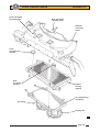
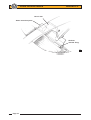
Early cars built before May 2004 will benefit from the fitment of an extended clamshell gutter (if not
already fitted). On later cars, the fettling of the clamshell was revised to prevent water spilling directly into the
actuator area.
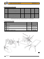
Parts Required
Gutter Extension Panel, RHD
Gutter Extension Panel, LHD
Part Number
A117B0703K
A117B0704K
Qty
1
1
1.
Remove both front body access panels, and the two louvre panels. Remove the two air deflector panels
to which the louvre panels attach.
2.
The rear of the radiator is secured by two pairs of screws along the top rear edge. Release the inboard
screw on each side.
3.
Before attempting to install the new gutter extension panel, protect the top surface of the radiator with a
rigid plastic sheet or similar to avoid damage to the delicate finning. Manoeuvre the gutter extension
panel into the underside of the clamshell spine, and retain with the two radiator fixing screws. Note that
the panel incorporates a hot air dam for the spine area.
4.
Refit the two air deflector panels, the louvres and the access panels.
Page 23