1
Lotus Service Notes
Section PL
Compressor
When the engine is running, and the refrigeration controls demand it, the electromagnetic clutch incorporated in the compressor pulley is energised, which then locks the pulley to the shaft and drives the compressor.
The rotary vane type compressor operates to discharge refrigerant vapour at high pressure and temperature
into the condenser. The compressor is lubricated by a quantity of special refrigerant oil, most of which is
retained in the compressor, with the remainder being circulated with the refrigerant. An integral thermal cut-out
switch is designed to prevent overheating damage by interrupting the compressor clutch circuit if an excessively high temperature is detected.
A thermostat, sensing the temperature of the refrigerated air as it leaves the evaporator, signals the
compressor to cycle on and off. In order to avoid engine stalling and to maintain idle speed when the compressor driving load is placed on the engine, the a.c. request and compressor command signals are processed by
the engine management ECU, which amends the idle air control valve position as necessary.
Condenser
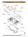
The aluminium condenser is horizontally mounted beneath the engine cooling radiator, and is of parallel
flow construction. The hot vapour received by the condenser from the compressor, releases heat to the
surrounding air via the condenser finning, with airflow boosted by two electric fans mounted below the condenser, and ram air flow caused by vehicle movement.
Evaporator
The evaporator is a tube and fin type heat exchanger mounted in a plastic housing fitted into the chassis
well ahead of the passenger compartment footwell. All incoming airflow is directed through the evaporator,
before being directed through or past the heater matrix, and then into the air distribution chamber.
The low pressure liquid refrigerant flowing into the evaporator via the expansion valve, begins to boil
(evaporate) and in so doing, draws the necessary heat for this process from the airstream passing through the
evaporator. This airstream is consequently cooled, and is directed through the various outlet vents to the
passenger compartment.
When the a.c. switch is pressed by the driver, and other parameters allow it (i.e. ignition on, blower fan
speed selected, a.c. pressure switch closed), the a.c. circuit is activated and the compressor clutch is engaged.
A thermostat, using a sensor inserted into the outlet side of the evaporator finning, monitors the temperature of
the refrigerated air and signals the compressor to cycle on and off in order to maintain outlet air temperature
just above freezing.
The inlet and outlet pipes connect to the evaporator via the expansion valve block, into which they are
sealed using 'O' rings and a clamp plate. The inlet is supplied from the receiver-drier, and the outlet feeds the
compressor.
Expansion Valve
The expansion valve block is fitted into the high and low pressure lines at the evaporator, and provides a
restriction to the flow of high pressure liquid into the evaporator, such that the consequent pressure drop
causes a change of state from a high temperature, high pressure liquid, to a low pressure, low temperature
atomised liquid.
By sensing the temperature and pressure of refrigerant leaving the evaporator, the expansion valve is
able to modulate the flow of refrigerant into the unit to optimise the cooling performance.
Receiver-Drier
The receiver-drier unit is fitted into the refrigerant line between the condenser and evaporator expansion
valve, and houses a screen sack filled with desiccant to absorb traces of moisture and other contaminants from
the refrigerant. The unit is mounted in the chassis well above the heater/a.c. unit. A sight glass built into the
top of the receiver-drier allows a visual assessment of refrigerant charge to be made - a clear sight glass may
indicate that the system is correctly charged, or completely empty, although the latter situation is usually
accompanied by oil streaks. If refrigerant charge is low, a stream of bubbles will be visible at the sight glass.
A trinary switch fitted into the top of the receiver-drier senses the pressure of refrigerant and allows
system operation only within a pressure range of 2 to 32 bar in order to prevent system damage from too high
a pressure, or from compressor oil starvation damage caused by too low a pressure. A third switching point is
used to engage the two condenser fans at half speed at pressures over 17.5 bar (see also sub-section KH.5).
An additional safeguard is provided in the form of a high pressure relief valve in the condenser inlet pipe, which
opens at 38 - 41 bar.
Page 4