1
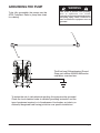
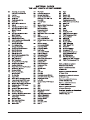
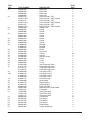
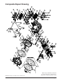
SERVICE AND OPERATING MANUAL
Model SB1-A / S B25A
II 2GD T5
CE
Type 4
Table of Contents
Principle of Operation............................................................................................. 1
Installation and Start-Up......................................................................................... 1
Air Supply............................................................................................................... 1
Installation Guide.................................................................................................... 2
Air Inlet & Priming................................................................................................... 3
Air Exhaust............................................................................................................. 3
Between Uses........................................................................................................ 3
Check Valve Servicing............................................................................................ 3
Diaphragm Servicing.............................................................................................. 3
Air Valve Lubrication............................................................................................... 3
ESADS+Plus®: Externally Serviceable Air Distribution System................................. 4
Pilot Valve............................................................................................................... 4
Pilot Valve Actuator................................................................................................. 5
Service Instructions: Troubleshooting .................................................................... 5
Warranty................................................................................................................. 5
Recommended Accessories................................................................................... 5
Important Safety Information.................................................................................. 6
Recycling................................................................................................................ 6
Grounding The Pump............................................................................................. 7
Material Codes....................................................................................................... 8
Declaration of Conformity....................................................................................... 9
Composite Repair Parts List................................................................................. 10
Composite Repair Drawing................................................................................... 12
Composite Repair Parts List for:
Dual Port Suction/Single Port Discharge................................................... 13
Dual Port Suction and Discharge............................................................... 13
Composite Repair Drawing for Dual Port Options................................................ 14
WARREN RUPP, INC. • A Unit of IDEX Corporation • P.O. Box 1568, Mansfield, Ohio 44901-1568 USA
Telephone (419) 524-8388 • Fax (419) 522-7867 • www.warrenrupp.com
sb1dl4sm-Rev0108
©Copyright 2007 Warren Rupp, Inc. All rights reserved.
SERVICE AND OPERATING MANUAL
Model SB1-A / S B25A
II 2GD T5
CE
Type 4
PLEASE NOTE!
The photos shown in this manual are for general instruction only. Your specific
model may not be shown. Always refer to the parts list and exploded view drawing
for your specific model when installing, disassembling or servicing your pump.
PRINCIPLE OF PUMP OPERATION
This ball valve pump is powered by compressed air and is a 1:1 pressure ratio
design. It alternately pressurizes the inner side of one diaphragm chamber, while
simultaneously exhausting the other inner chamber. This causes the diaphragms,
which are connected by a common rod, to move endwise. Air pressure is applied
over the entire surface of the diaphragm, while liquid is discharged from the opposite side. The diaphragm operates under a balanced condition during the discharge
stroke, which allows the unit to be operated at discharge heads over 200 feet (61
meters) of water head.
Since the diaphragms are connected by a common rod, secured by plates to the
center of the diaphragms, one diaphragm performs the discharge stroke, while the
other is pulled to perform the suction stroke in the opposite chamber.
For maximum diaphragm life, keep the pump as close to the liquid being pumped
as possible. Positive suction head in excess of 10 feet of liquid (3.048 meters) is not
recommended. For applications with higher suction heads, consult the factory.
Alternate pressuring and exhausting of the diaphragm chamber is performed by
means of an externally mounted, pilot operated, four-way spool type air distribution
valve. When the spool shifts to one end of the valve body, inlet air pressure is applied to one diaphragm chamber and the other diaphragm chamber exhausts. When
the spool shifts to the opposite end of the valve body, the porting of chambers is
reversed. The air distribution valve spool is moved by an internal pilot valve which
alternately pressurizes one side of the air distribution valve spool, while exhausting
the other side. The pilot valve is shifted at each end of the diaphragm stroke by the
diaphragm plate coming in contact with the end of the pilot valve spool. This pushes
it into position for shifting of the air distribution valve.
The chambers are manifolded together with a suction and discharge check valve
for each chamber, maintaining flow in one direction through the pump.
INSTALLATION & START-UP
Locate the pump as close to the product being pumped as possible, keeping
suction line length and number of fittings to a minimum. Do not reduce line size.
For installations of rigid piping, short flexible sections of hose should be
installed between pump and piping. This reduces vibration and strain to the piping
system. A Warren Rupp Tranquilizer® surge suppressor is recommended to further
reduce pulsation in flow. Tighten all fasteners before pump startup.
This pump was tested at the factory prior to shipment and is ready for operation.
It is completely self-priming from a dry start for suction lifts of 10-15 feet (3.05-4.57
meters) or less. For suction lifts exceeding 15 feet of liquid, fill the chambers with
liquid prior to priming.
AIR SUPPLY
Air supply pressures cannot exceed 125 psi (8.61 bar). Connect the pump
air inlet to an air supply of sufficient capacity and pressure required for desired
performance. When the air line is solid piping, use a short length of flexible hose
(not less than 3/4" (19mm) in diameter) between pump and piping to eliminate
strain to pipes.
sb1dl4sm-REV0108
Models SB1-A & SB25A Page 1
INSTALLATION GUIDE
Top Discharge Ball or Flap Valve Unit
CAUTION
Available from
Warren Rupp
The air exhaust should be
piped to an area for safe
disposition of the product
being pumped, in the event
of a diaphragm failure.
1 Tranquilizer®/Surge Supressor
2 Filter/Regulator
3 Air Dryer
1
Surge
Suppressor
2
sb1dl4sm-REV0108
3
Models SB1-A & SB25A Page 2
AIR INLET & PRIMING
For start-up, open an air valve approximately 1/2" to 3/4" turn. After the unit
primes, an air valve can be opened to increase flow as desired. If opening the valve
increases cycling rate, but does not increase flow rate, cavitation has occurred, and the
valve should be closed slightly.
For the most efficient use of compressed air and the longest diaphragm life, throttle
the air inlet to the lowest cycling rate that does not reduce flow.
AIR EXHAUST
If a diaphragm fails, the pumped liquid or fumes can enter the air end of the pump,
and be exhausted into the atmosphere. When pumping hazardous or toxic materials,
pipe the exhaust to an appropriate area for safe disposition.
This pump can be submerged if materials of construction are compatible with the
liquid. The air exhaust must be piped above the liquid level. Piping used for the air
exhaust must not be smaller than 1" (2.54 cm). Reducing the pipe size will restrict air
flow and reduce pump performance. When the product source is at a higher level than
the pump (flooded suction), pipe the exhaust higher than the product source to prevent
siphoning spills.
Freezing or icing-up of the air exhaust can occur under certain temperature and
humidity conditions. Use of an air dryer should eliminate most icing problems.
BETWEEN USES
When used for materials that tend to settle out or transform to solid form, the pump
should be completely flushed after each use, to prevent damage. Product remaining
in the pump between uses could dry out or settle out. This could cause problems with
valves and diaphragms at re-start. In freezing temperatures, the pump must be drained
between uses in all cases.
CHECK VALVE SERVICING
Need for inspection or service is usually indicated by poor priming, unstable
cycling, reduced performance or the pump’s cycling but not pumping.
Remove the six flange bolts securing the inlet and outlet flanges to the manifold. Inspect the surfaces of both check valve and seat for wear or damage that could prevent
proper sealing. If pump is to prime properly, valves must seat air tight.
DIAPHRAGM SERVICING
Remove the four bolts securing the manifold flange to the chamber. Remove the eight
nuts securing the outer diaphragm chamber flange and remove the chamber. Loosen
the capscrew securing the diaphragm and plate to the rod by leaving the diaphragm
engaged with the capscrews around the outer flange, preventing rotation of the rod. DO
NOT USE A WRENCH ON THE DIAPHRAGM ROD. FLAWS ON THE SURFACE MAY
DAMAGE BEARINGS AND SEAL.
During reassembly make certain that the rubber bumper is on the rod on each
side. Install the diaphragm with the natural bulge outward as indicated on the
diaphragm. Install the heavier plate on the outside of the diaphragm and make
certain that the large radius side of both plates are toward the diaphragm. Place the
sealing washer between the inner diaphragm plate and the end of the rod. Tighten the
capscrew to approximately 25 ft. lbs. (33.9 Newton meters). Torque while allowing diaphragm to turn freely with plates. Except for EPDM Rubber, use a lightweight oil between
plates and diaphragm when doing this procedure. Use a wrench on the capscrew of the
opposite side to keep the rod from rotating. If the opposite chamber is assembled, the
rod need not be held.
When reassembling the outer chambers and the manifold, the bolts securing the
manifold flange to the chamber should be snugged prior to tightening the chamber
bolts, to insure that the chamber port flange is square with the manifold flange. Finish
tightening the manifold flange bolts after chamber bolting is secured.
AIR VALVE LUBRICATION
The SANDPlPER pump’s pilot valve and main air valve assemblies are
designed to operate WITHOUT lubrication. This is the preferred mode of
operation. There may be instances of personal preference, or poor quality air
supplies when lubrication of the compressed air supply is required. The pump air
system will operate with properly lubricated compressed air supplies. Proper lubrication of the
compressed air supply would entail the use of an air line lubricator (available from Warren
sb1dl4sm-REV0108
Models SB1-A & SB25A Page 3
Rupp) set to deliver one drop of 10 weight, non-detergent oil for every 20 SCFM of air
the pump consumed at its point of operation. Consult the pump’s published Performance
Curve to determine this.
It is important to remember to inspect the sleeve and spool set routinely. It should
move back and forth freely. This is most important when the air supply is lubricated. If a
lubricator is used, oil accumulation will, over time, collect any debris from the compressed
air. This can prevent the pump from operating properly.
Water in the compressed air supply can create problems such as icing or freezing
of the exhaust air causing the pump to cycle erratically, or stop operating. This can
be addressed by using a point of use air dryer to supplement a plant’s air drying equipment. This device will remove excess water from the compressed air supply and alleviate
the icing or freezing problem.
ESADS+Plus®: Externally Serviceable Air
Distribution System
Please refer to the exploded view drawing and parts list in the Service Manual supplied with your pump. If you need replacement or additional copies, contact your local
Warren Rupp Distributor, or the Warren Rupp factory Literature Department. To receive
the correct manual, you must specify the MODEL and TYPE information found on the
name plate of the pump.
The main air valve sleeve and spool set is located in the valve body mounted on the
pump with four hex head capscrews. The valve body assembly is removed from the pump
by removing these four hex head capscrews.
With the valve body assembly off the pump, access to the sleeve and spool set is
made by removing a retaining ring (each end) securing the end cap on the valve body
assembly. With the end caps removed, slide the spool back and forth in the sleeve.
The spool is closely sized to the sleeve and must move freely to allow for proper pump
operation. An accumulation of oil, dirt or other contaminants from the pump’s air supply,
or from a failed diaphragm, may prevent the spool from moving freely. This can cause
the spool to stick in a position that prevents the pump from operating. If this is the case,
the sleeve and spool set should be removed from the valve body for cleaning and further
inspection.
Remove the spool from the sleeve. Using an arbor press or bench vise (with an
improvised mandrel), press the sleeve from the valve body. Take care not to damage
the sleeve. At this point, inspect the o-rings on the sleeve for nicks, tears or abrasions.
Damage of this sort could happen during assembly or servicing . A sheared or cut
o-ring can allow the pump’s compressed air supply to leak or bypass within the air valve
assembly, causing the pump to leak compressed air from the pump air exhaust or not
cycle properly. This is most noticeable at pump dead head or high discharge pressure
conditions. Replace any of these o-rings as required or set up a routine, preventive
maintenance schedule to do so on a regular basis. This practice should include cleaning the spool and sleeve components with a safety solvent or equivalent, inspecting for
signs of wear or damage, and replacing worn components.
To re-install the sleeve and spool set, lightly lubricate the o-rings on the sleeve
with an o-ring assembly lubricant or lightweight oil (such as 10 wt. air line lubricant). Re-install one end cap, and retaining ring (see safety warning), on the valve
body. Using the arbor press or bench vise that was used in disassembly, carefully press the sleeve back into the valve body, without shearing the o-rings. Reinstall the spool, opposite end cap and retaining ring (see safety warning), on the
valve body. After inspecting and cleaning the gasket surfaces on the valve body and
intermediate, reinstall the valve body on the pump using new gaskets. Tighten the four
hex head capscrews evenly and in an alternating cross pattern, at 150 in./lbs. (16.94
Newton meters).
SAFETY WARNING
To assure proper pump function and safe installation of the
retaining ring, check the gap “G”
dimension for full installation
into the valve body grooves.
> .232 "G"
Dimensions between lugs
PILOT VALVE
The pilot valve assembly is accessed by removing the main air distribution valve body
from the pump and lifting the pilot valve body out of the intermediate housing.
Most problems with the pilot valve can be corrected by replacing the o-rings. Always
grease the spool prior to inserting it into the sleeve. If the sleeve is removed from the
body, reinsertion must be at the chamfered side. Grease the o-rings to slide the sleeve
into the valve body. Securely insert the retaining ring around the sleeve. When reinserting the pilot valve, push both plungers (located inside the intermediate bracket) out of
the path of the pilot valve spool ends to avoid damage.
sb1dl4sm-REV0108
Models SB1-A & SB25A Page 4
PILOT VALVE ACTUATOR
Bushings for the pilot valve actuators are held in the inner chambers with retaining rings. An o-ring is behind each bushing. If the plunger has any sideways motion,
check o-rings and bushing for deterioration or wear. The plunger may be removed
for inspection or replacement. First remove the air distribution valve body and the
pilot valve body from the pump. The plungers can be located by looking into the
intermediate. It may be necessary to use a fine piece of wire to pull them out.
The bushing can be turned out through the inner chamber by removing the outer
chamber assembly. Replace the bushings if pins have bent.
SERVICE INSTRUCTIONS: TROUBLE SHOOTING
Pump will not cycle
A. Check to make sure the unit has enough pressure to operate and that the air inlet
valve is open.
B. Check the discharge line to insure that the discharge line is neither closed nor
blocked.
C. It the spool in the air distribution valve is not shifting, check the main spool. It must
slide freely.
D. Excessive air leakage in the pump can prevent cycling. This condition will be evident.
Air leakage into the discharge line indicates a ruptured diaphragm. Air leakage from
the exhaust port indicates leakage in the air distribution valve. See further service
instructions.
E. Blockage in the liquid chamber can impede movement of diaphragm.
Pump cycles but will not pump
A. Suction side of pump pulling in air. Check the suction line for air leaks and be sure that
the end of the suction line is submerged. Check flange bolting. Check valve flanges
and manifold to chamber flange joints.
B. Make certain the suction line or strainer is not plugged. Restriction at the suction is
indicated by a high vacuum reading when a vacuum gauge is installed in the suction
line.
C. Check valves may not be seating properly. To check, remove the suction line and cover
the suction port with your hand. If the unit does not pull a good suction (vacuum), the
check valves should be inspected for proper seating.
D. Static suction lift may be too high. Priming can be improved by elevating the suction
and discharge lines higher than the check valves and pouring liquid into the unit
through the suction inlet. When priming at high suction lifts or with long suction lines
operate the pump at maximum cycle rate.
Low performance
A. Capacity is reduced as the discharge pressure increases, as indicated on the performance curve. Performance capability varies with available inlet air supply. Check air
pressure at the pump inlet when the pump is operating to make certain that adequate
air supply is maintained.
B. Check vacuum at the pump suction. Capacity is reduced as vacuum increases. Reduced flow rate due to starved suction will be evident when cycle rate can be varied
without change in capacity. This condition will be more prevalent when pumping viscous liquids. When pumping thick, heavy materials the suction line must be kept as
large in diameter and as short as possible, to keep suction loss minimal.
C. Low flow rate and slow cycling rate indicate restricted flow through the discharge
line. Low flow rate and fast cycling rate indicate restriction in the suction line or air
leakage into suction.
D. Unstable cycling indicates improper check valve seating on one chamber. This condition is confirmed when unstable cycling repeats consistently on alternate exhausts.
Cycling that is not consistently unstable may indicate partial exhaust restriction due to
freezing and thawing of exhaust air. Use of an air dryer should solve this problem.
For additional information, see the Warren Rupp Troubleshooting Guide.
RECOMMENDED WARREN RUPP
ACCESSORIES TO MAXIMIZE
PUMP PERFORMANCE:
• Tranquilizer® Surge Suppressor.
For nearly pulse-free flow.
• Warren Rupp Filter/Regulator.
For modular installation and
service convenience.
• Warren Rupp Speed Control.
For manual or programmable
process control. Manual adjustment
or 4‑20mA reception.
For more detailed information on
these accessories, contact your local
Warren Rupp Factory-Authorized
Distributor, or Warren Rupp corporate
headquarters or visit:
www.warrenrupp.com
warranty
This pump is warranted for a period of five years against defective material and
workmanship. Failure to comply with the recommendations stated in this manual voids
all factory warranty.
sb1dl4sm-REV0108
Models SB1-A & SB25A Page 5
IMPORTANT SAFETY
INFORMATION
IMPORTANT
Read these safety warnings
and instructions in this
manual completely, before
installation and start-up
of the pump. It is the responsibility of the
purchaser to retain this manual for reference.
Failure to comply with the recommendations
stated in this manual will damage the pump,
and void factory warranty.
CAUTION
Before pump operation,
inspect all gasketed
fasteners for looseness
caused by gasket creep. Retorque loose fasteners to
prevent leakage. Follow recommended torques
stated in this manual.
WARNING
Take action to prevent static
sparking. Fire or explosion
can result, especially when
handling flammable liquids.
The pump, piping, valves,
containers or other miscellaneous equipment
must be grounded. (See page 32)
WARNING
This pump is pressurized
internally with air pressure
during operation. Always
make certain that all bolting
is in good condition and
that all of the correct
bolting is reinstalled during assembly.
WARNING
When used for toxic or
aggressive fluids, the pump
should always be flushed
clean prior to disassembly.
WARNING
WARNING
Before maintenance or
repair, shut off the compressed air line, bleed the
pressure, and disconnect
the air line from the pump.
The discharge line may be
pressurized and must be bled of its pressure.
WARNING
In the event of diaphragm
rupture, pumped material
may enter the air end of the
pump, and be discharged
into the atmosphere. If
pumping a product which is hazardous or toxic,
the air exhaust must be piped to an appropriate
area for safe disposition.
Before doing any maintenance on the pump, be
cer tain all pressure is
completely vented from the
pump, suction, discharge,
piping, and all other openings and connections.
Be certain the air supply is locked out or made
non‑operational, so that it cannot be started
while work is being done on the pump. Be certain
that approved eye protection and protective
clothing are worn all times in the vicinity of the
pump. Failure to follow these recommendations
may result in serious injury or death.
WARNING
Airborne particles and
loud noise hazards.
Wear ear and eye
protection.
RECYCLING
Many components of SANDPIPER® AODD pumps are made
of recyclable materials (see chart on page 9 for material
specifications). We encourage pump users to recycle worn out parts
and pumps whenever possible, after any hazardous pumped fluids
are thoroughly flushed.
Pump complies with EN809 Pumping Directive, Directive 98/37/
EC Safety of Machinery, and Directive 94/9/EC, EN13463-1
Equipment for use in Potentially Explosive Environments. For
reference to the directive certificates visit: www.warrenrupp.com.
The Technical File No. AX1 is stored at KEMA, Notified Body 0344,
under Document #203040000.
sb1dl4sm-REV0108
CE
II 2GD T5
Models SB1-A & SB25A Page 6
Grounding The Pump
To be fully groundable, the pumps must be
ATEX Compliant. Refer to pump data sheet
for ordering.
WARNING
Take action to prevent static sparking.
Fire or explosion can result,
especially when handling flammable liquids.
The pump, piping, valves, containers or
other miscellaneous equipment must be
grounded.
This 8 foot long (244 centimeters) Ground
Strap, part number 920-025-000 can be
ordered as a service item.
To reduce the risk of static electrical sparking, this pump must be grounded.
Check the local electrical code for detailed grounding instruction and the
type of equipment required, or in the absence of local codes, an industry or
nationally recognized code having juristiction over specific installations.
sb1dl4sm-REV0108
Models SB1-A & SB25A Page 7
sb1dl4sm-REV0108
Models SB1-A & SB25A Page 8
Declaration of Conformity
Declaration of Conformity
Warren Rupp, Inc., 800 North Main Street, Mansfield, Ohio,
certifies that Air-Operated Double Diaphragm Metallic Pumps Series:
HDB, HDF, M Non-Metallic, S Non-Metallic, M Metallic, S Metallic,
Containment Duty, Gas, UL, High Pressure, W, Submersible and
Tranquilizers comply with the European Community Directive 98/37/EC,
Safety of Machinery. This product has used EN 809, Pumps and Pump
Units for Liquids - Common Safety Requirements harmonized standard
to verify conformance.
October 20, 2005
Signature of authorized person
Date of issue
David Roseberry
Engineering Manager
Printed name of authorized person
Title
CE
sb1dl4sm-REV0108
Models SB1-A & SB25A Page 9
SERVICE AND OPERATING MANUAL
Model SB1-A / S B25A
II 2GD T5
CE
Type 4
Composite Repair Parts List
ITEM
NO.
PART NUMBER
DESCRIPTION
1
2
3
4
5
5A
5B
5C
5D
5E
5F
6
7
8
9
10
11
12
13
14
15
16
17
18
19
20
21
22
23
24
031.039.000
050.008.354
050.008.356
050.008.360
050.008.363
050.008.365
050.011.600
070.012.170
095.051.558
095.074.000
095.071.551
755.025.162
560.033.360
775.014.115
560.023.360
675.037.080
114.007.157
114.012.010
115.071.330
115.070.330
132.019.360
132.022.360
135.034.506
165.038.356
165.042.157
165.042.558
170.029.330
170.032.330
170.033.330
170.045.330
170.047.330
170.063.115
171.010.330
196.012.110
196.012.112
196.012.157
196.042.157
196.090.010
196.043.157
196.084.010
255.012.335
286.008.354
286.008.356
286.008.360
sb1dl4sm-REV0108
TOTAL
RQD.
Sleeve and Spool Set
Check Ball
Check Ball
Check Ball
Check Ball
Check Ball
Check Ball
Sleeeve Bearing
Valve Body
Pilot Valve Assembly
Pilot Valve Body
Pilot Valve Sleeve
O-ring
Pilot Valve Spool
O-ring
Retaining Ring
Intermediate Bracket
Intermediate Bracket (cast iron centers)
Mounting Bracket
Mounting Bracket (top ported only)
Bumper
Actuator Bumper
Bushing
End Cap
Valve Body Cap
Valve Body Cap (cast iron centers)
Hex Capscrew Hex Capscrew 1/4-20 x 1.00
Hex Capscrew 3/8-16 x 3.25
Hex Capscrew Hex Capscrew Hex Capscrew Flanged Capscrew
Outer Chamber
Outer Chamber
Outer Chamber
Inner Chamber
Inner Chamber (cast iron centers)
Inner Chamber
Inner Chamber (cast iron centers)
Pipe Coupling 3/4 NPT
Diaphragm
Diaphragm
Diaphragm
1
4
4
4
4
4
4
2
1
1
1
1
4
1
4
1
1
1
1
1
2
2
2
2
1
1
16
6
4
4
6
1
4
2
2
2
1
1
1
1
1
2
2
2
Models SB1-A & SB25A Page 10
ITEM
NO.
PART NUMBER
DESCRIPTION
24
25
26
27
28
29
30
31
32
33
34
35
36
37
38
39
40
41
42
43
43A
44
45
46
47
48
49
50
51
52
53
54
55
56
57
286.008.363
286.008.364
286.008.365
286.008.366
334.013.110
334.013.110 E
334.013.112
334.013.112 E
334.013.157
334.013.157 E
350.002.360
360.030.426
360.030.600
360.031.379
360.031.384
360.031.608
360.056.379
360.057.360
360.058.360
518.006.110
518.006.112
518.006.156
530.036.000
542.001.330
545.004.330
545.005.330
547.002.330
560.001.360
560.040.360
560.058.360
612.022.330
612.101.110
612.101.112
612.108.157
618.003.330
618.003.110
618.003.112
618.003.330
620.007.114
675.040.360
675.042.115
675.043.115
685.039.120
706.013.330
720.010.375
722.026.580
722.047.110
722.047.112
900.004.330
901.005.330
901.012.180
901.035.330
905.001.015
286.015.604
sb1dl4sm-REV0108
Diaphragm
Diaphragm
Diaphragm
Diaphragm
Porting Flange 1" NPT
Porting Flange 1" BSP Tapered
Porting Flange 1" NPT
Porting Flange 1" BSP Tapered
Porting Flange 1" NPT
Porting Flange 1" BSP Tapered
Rubber Foot
Gasket
Gasket
Gasket
Gasket
Gasket
Gasket
Gasket
Gasket
Manifold
Manifold
Manifold
Muffler
Square Nut
Hex Nut
Hex Nut
Stop Nut 1/4-20
O-ring
O-ring
O-ring
Inner Diaphragm Plate
Outer Diaphragm Plate
Outer Diaphragm Plate
Outer Diaphragm Plate
Pipe Plug 1/4 NPT
Pipe Plug 1/4 NPT
Pipe Plug 1/4 NPT
Pipe Plug 1/4 NPT
Actuator Plunger
Sealing Ring
Retaining Ring
Retaining Ring
Diaphragm Rod
Machine Screw 1/4-20 Slotted
U-Cup Seal
Check Valve Seat
Check Valve Seat
Check Valve Seat
Lock Washer
Flat Washer
Flat Washer
Flat Washer
Taper Washer
Overlay Diaphragm
TOTAL
RQD.
2
2
2
2
2
2
2
2
2
2
4
2
2
4
4
4
1
1
1
1
1
1
1
1
26
4
4
2
2
8
2
2
2
2
3
2
2
2
2
2
2
2
1
4
2
2
2
2
10
4
2
7
4
2
Models SB1-A & SB25A Page 11
Composite Repair Drawing
19
56
17
25
51
28
28
32
51
28
28
52
2
2
35
7
27
6
43
14
39
49
29
55
37
26
52
35
5D
5A
9
5F
45
44
16
22
30
5E
48
43
3
4
33
23
5B
46
5C
13
10
38
34
50
24
31
8
12
1
54 41
53
42
55
36
18
40
15
35
11 47
24
57
42
sb1dl4sm-REV0108
OVERLAY UNITS
43A
©2007 Warren Rupp, Inc. All rights reserved. Printed in U.S.A.
®Warren Rupp, SANDPIPER and Tranquilizer
are registered tradenames of Warren Rupp, Inc.
®Neverseize is a registered tradename of Loctite
Models SB1-A & SB25A Page 12
Composite Repair Parts List for
Dual Port Suction/Single Port Discharge
ITEM
NO.
PART NUMBER
DESCRIPTION
17
25
58
59
170.047.330
334.013.110
334.013.110 E
334.013.112
334.013.112 E
334.013.157
334.013.157 E
334.036.110
334.036.110 E
334.036.112
334.036.112 E
334.036.156
334.036.156 E
170.121.330
TOTAL
RQD.
Hex Capscrew
Porting Flange 1" NPT
Porting Flange 1" BSP Tapered
Porting Flange 1" NPT
Porting Flange 1" BSP Tapered
Porting Flange 1" NPT
Porting Flange 1" BSP Tapered
Dual Porting Flange 1" NPT
Dual Porting Flange 1" BSP Tapered
Dual Porting Flange 1" NPT
Dual Porting Flange 1" BSP Tapered
Dual Porting Flange 1" NPT
Dual Porting Flange 1" BSP Tapered
Hex Capscrew 5/16-18 x 5.50 long
3
1
1
1
1
1
1
1
1
1
1
1
1
3
Dual Port Suction and Discharge
ITEM
NO.
PART NUMBER
DESCRIPTION
17
58
60
170.047.330
334.036.110
334.036.110 E
334.036.112
334.036.112 E
334.036.156
334.036.156 E
170.084.330
TOTAL
RQD.
Hex Capscrew
Dual Porting Flange 1" NPT
Dual Porting Flange 1" BSP Tapered
Dual Porting Flange 1" NPT
Dual Porting Flange 1" BSP Tapered
Dual Porting Flange 1" NPT
Dual Porting Flange 1" BSP Tapered
Hex Capscrew 5/16-18 x 7.00 long
1
Available in kit form. Order P/N 031-060-000 which also includes items 2, 13, 15, 31, & 45.
2
Available in kit form, Air End Kit 476-103-000.
3
2
2
2
2
2
2
3
Wet End Kits for SB1-A & SB25A:
Kit Number
Pump Type
476-034-354
476-034-356
SR
476-034-360
SB
476-034-363
SV
476-034-365
SN
476-034-633
SC
476-034-634
SH
476-034-635
SGN
476-034-638
SGR
sb1dl4sm-REV0108
Models SB1-A & SB25A Page 13
Composite Repair Drawing for Dual Port Options
60
DUAL PORT SUCTION
AND DISCHARGE
DUAL PORT SUCTION
SINGLE PORT DISCHARGE
59
17
17
58
25
58
58
sb1dl4sm-REV0108
Models SB1-A & SB25A Page 14