1
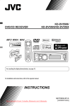
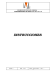
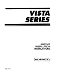
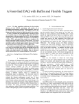
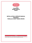
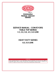
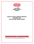
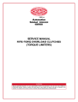
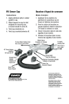
SERVICE MANUAL
OVERLOAD CLUTCHES
FOR INDEX DRIVES
WARNING
This is a controlled document. It is your responsibility to deliver this information to the end user of the CAMCO or
FERGUSON product. Failure to deliver this could result in your liability for injury to the user or damage to the
machine. For copies of this manual, call your Customer Service Representative at 800-645-5207
INSTALLATION, OPERATION AND
MAINTENANCE INSTRUCTIONS
7. Dowel pins and mounting screws must not
protrude from the drive plate or driven
member as the clutch could become a solid
coupling.
SAFETY INSTRUCTIONS
1. Read your Overload Clutch InstallationOperation Instructions thoroughly before
operating the unit, for your safety and the
protection of your unit.
8. High humidity, contaminants, or wash down
applications may cause rust within the
clutch, resulting in operational failure.
Lubricate every six months or more frequently as the application requires.
2. CAMCO Overload Clutches are designed to
protect the Index Drive only and will not
protect against bodily injury.
9. The CAMCO clutch is not a "FAIL SAFE"
device and cannot be used on "overhauling"
or "holding" load applications.
3. Double check to be sure the power is off
and cannot be turned on while working on
the equipment.
The above list includes major safety points to
be observed, but should not be considered as
limiting in safety precautions to be followed.
4. Use extreme caution with jammed or unbalanced loads, which when cleared may set
the machine in motion.
OPERATING PRINCIPLE
CAMCO Overload Clutches are designed
for mounting on the output member of the
CAMCO Index Drive. An Index Drive is essentially a variable ratio speed reducer. Each index
provides an incremental output to input torque
ratio, which may range from 1:1 in the center of
the motion, to as high as 1000:1 in the beginning or end of the motion. As output torque
equals input torque times the ratio, a clutch
mounted on the input side provides no protection at the beginning or end of the motion.
5. Keep all objects such as hands, clothing,
tools away from rotating or moving parts.
6. Use safety glasses or equivalent to protect
your eyes.
Fig.1
SWITCH NORMALLY
CLOSED
DETECTOR
PLATE
CAMCO Overload Clutches provide zero
backlash, high rigidity, low inertia and are
specifically designed to be used in conjunction
with CAMCO Index Drives.
BODY
Power is transmitted from the Index Drive
through the body of the CAMCO Overload
Clutch. The body contains spring loaded
tapered plungers that engage in mating tapered seats in the drive plate. (See Fig. 1.)
Torque settings are determined by the pressure
the calibrated springs "seat" the plungers.
DRIVE PLATE
DRIVING
POSITION,
TYPICAL FOR
EACH PLUNGER
Fig.2
OVERLOAD POSITION,
DETECTOR PLATE IS
MOVED AXIALLY TOWARD
SWITCH BY TRAVEL OF
PLUNGERS
PLUNGER
DRIVE PLATE
SWITCH OPEN
WITHIN 0.008"
DEFLECTION OF
DETECTOR PLATE
When an overload occurs, which exceeds the
torque setting of the clutch, the breakaway
friction between the tapered plunger and the
tapered seat, forces the plungers outward from
their seats. The movement of the plungers
elevates the detector plate, actuating the limit
switch. (See Fig. 2.)
The CAMCO Overload Clutch always resets in
its original position, making it an excellent
choice on applications that must remain
registered or timed.
PLUNGER
DRIVE PLATE
2
CLUTCH TYPES
CAMCO clutches are designed to meet specific application
requirements. They are available in five basic designs.
.39C
2.3C
6.0C
11C
25C
41C
TYPE C
.39FC
2.3FC
6.0FC
11FC
25FC
41FC
TYPE FC
.39F
2.3F
6.0F
11F
25F
41F
140F
.39S
2.3S
6.0S
11S
25S
41S
2.8D
4.0D
7.8D
18D
31D
32D
61D
130D
• Clamped Hub
• Clamped Body
• Shrink Disc
A clutch coupling which can be mounted on Index Drives
without output flanges. They provide a positive, rigid
connection between two shafts.
LIMIT SWITCH
• Flange Mounted Body
• Clamped Hub
• Shrink Disc
These clutch couplings flange mount to the ouput shaft
of the Index Drive and provide a keyed-clamped hub
connection to the driven shaft.
TYPE F
LIMIT SWITCH
DRIVEN MEMBER MAY BE DIAL
PLATE, SPROCKET,
GEAR, ETC.
• Shaft Mounted Body
The type F Clutch flange mounts to
the output shaft of the Index Drive
and provides a mounting surface for a
dial plate, sprocket, gear, etc., resulting in a rigid, compact and accurate
connection to the driven member.
LIMIT SWITCH
LIMIT
SWITCH
MOUNTING A
DRIVEN MEMBER MAY BE DIAL
PLATE, SPROCKET, GEAR, ETC.
TYPE S
MOUNTING B
DRIVEN MEMBER MAY BE DIAL PLATE,
SPROCKET, GEAR, ETC.
•Shaft Mounted
• Clamped Body
• Shrink Disc
The combination of a key and clamped
hub construction provides rigid and
backlash-free shaft connections. The
Type S clutch is designed to mount on
Index Drives without flanges.
MOUNTING A
LIMIT
SWITCH
DRIVEN MEMBER MAY BE DIAL PLATE,
SPROCKET, GEAR, ETC.
TYPE D
• Flange Mounted
These units are designed to mount on CAMCO Index
Drives featuring large output mounting surfaces. The dial
plate rests directly on the Index Drive output flange,
providing the ultimate in stability and accuracy.
3
MOUNTING B
LIMIT SWITCH
INSTALLATION AND REMOVAL
INSTRUCTIONS FOR SHRINK DISCS
IMPORTANT!
Carefully Clean
Shaft & Hub Bore
& Keep Free of Any
Lubricant
Outer Collars
Shrink Discs are supplied ready for installation. However, prior to tightening of locking
screws it is necessary to remove wooden
spacers located between outer collars, which
are used during shipment of Shrink Discs.
Hub
Inner Ring
INSTALLATION
Important: Never tighten locking screws
before shaft installation, since inner ring of
Shrink Discs as well as hub can be permanently contracted even at relatively low
tightening torques.
Shaft
Metrix Hex Head Locking Screws
DIN 931, Grade 10.9
1 Clean hub O.D. and Shrink Disc bore and
lightly lubricate hub O.D. before assembly
of Shrink Disc on hub.
NOTE: It is not necessary to check tightening
torque again after installation is completed or
equipment has been in operation.
2 Carefully clean shaft and hub bore from
any lubricant prior to mounting hub onto
shaft. THIS STEP IS VERY IMPORTANT,
since it will greatly affect the torque
transmitting capability of a Shrink Disc
connection.
REMOVAL
1. Loosen locking screws in several stages by
using approx. 1/2 turns, following either a
clock or counterclockwise sequence till Shrink
Disc can be moved on hub. DO NOT remove
locking screws completely.
3 After checking correct position of Shrink
Disc and hub, handtighten 3 or 4 equally
spaced locking screws and make sure that
outer collars of Shrink Disc are in a parellel
position. Afterwards handtighten rest of
locking screws.
2. Make sure any rust buildup in front of hub
is removed before hub is pulled from shaft.
RE-INSTALLATION OF SHRINK DISC
In relatively clean operating conditions, Shrink
Discs can be re-used without prior cleaning.
Severe conditions, however, require thorough
cleaning and re-lubrication with the following
or similar lubricants:
Tapers of inner rings and outer collar
bores: Molykote 3321 R-spray or
Molykote G RAPlD-spray or paste
4 Use torque wrench and equally tighten all
screws one after another in a clock or
counterclockwise sequence by approx.
1/4 turns (even if initially some screws will
require a very low tightening torque) until
specified tightening torque MA is reached.
NOTE: To compensate for bolt setting
during installation, a 5% higher than
specified tightening torque is recommended for final tightening round.
Screwthreads and head contact area:
Multipurpose grease like Molykote BR-2
Damaged O-rinqs should be replaced.
5 Reset torque wrench and make sure that
no screw will turn at specified tightening
torque MA.
LOCKING SCREW-TIGHTENING TORQUES "MA"
screw size
s mm
MA [Nm]
MA [ft.-lbs]
M5
M6
M8
M10
M12
M16
M20
M24
M27
8
10
13
17
19
24
30
36
41
5
12
30
59
100
250
490
840
1250
3.6
8.7
22
44
74
185
362
620
922
4
SHRINK DISC COUPLINGS
IFOR RIGID SHAFT CONNECTIONS- TRANSMIT TORQUES &
BENDING MOMENTS- PERMIT AXIAL & ANGULAR TIMING
RECOMMENDED SLEEVE DIMENSIONS FOR
SHRINK DISC COUPLINGS USING SERIES 01
& SERIES 03 SHRINK DISC SIZE 140 &
LARGER
SHRINK DISC (PREFERABLY USE UNITS WITH INTEGRATED HUB STOP) REFER
TO SHRINK DISC SPECIFICATION TABLE FOR SELECTION OF SHRINK DISC TO
MEET YOUR TORQUE & SHAFT SIZE REQUIREMENTS. CONSULT WITH US IF A
BENDING MOMENT HIGHER THAN 25% OF RATED TORQUE HAS TO BE
TRANSMITTED.
SHRINK DISC
SIZE
U
V
SERIES 01
SERIES 03
140
5/8
1/8
8.00
9.00
145 thru 155
5/8
1/8
8.38
9.50
160 thru 175
7/8
1/8
9.00
10.50
180 thru 200
7/8
3/16
11.00
12.63
220
7/8
3/16
12.25
14.38
240
1
3/16
13.25
15.38
260
1
3/16
14.00
16.63
280
1-1/4
1/4
15.50
18.25
OPTIONAL RECESS
ON SLEEVE O.D.
300
1-1/4
1/4
16.25
18.50
320
1-1/4
1/4
16.25
19.00
ONLY IF SHRINK
DISCS WITH
INTEGRATED HUB
STOPS ARE USED
340
1-1/2
1/4
17.75
21.00
350 & 360
1-1/2
1/4
18.25
21.25
380 & 390
1-1/2
5/16
18.75
22.25
420
1-3/4
5/16
21.00
24.75
440 & 460
1-3/4
3/8
22.25
26.25
480 & 500
1-3/4
3/8
23.75
28.25
CHAMFER ≥ 15˚
COUPLING SLEEVE CAN BE SUPPLIED BY BIKON CORP. USE
MATERIAL WITH A YEILD POINT OF AT LEAST 36000 PSI FOR LIGHT
DUTY APPLICATIONS, BUT AISE 1045 (OR BETTER) FOR MEDIUM DUTY
APPLICATIONS.
SEE SHRINK DISC SPECIFICATION TABLE FOR DIMENSIONS "L" & 'e"
REQUIRED
ASSEMBLIES
(FIG. 3)
HUB
FLANGE PLATE
DRIVE PLATE
BODY (S, C)
DETECTOR PLATE
BODY (F, FC)
PLUNGERS
SPRINGS
CLUTCH TYPE
C FC F S
➊
∑
∏
π
∫
➊
TYPES C, FC AND F, S
∑ ∑ ∑ CLUTCHES
∏ ∏ ∏
π
∫ ∫ ∫
Ω
❻ ❻
❼ SPRING
DOWEL PIN
PLUNGER
❼ ❼ ❼ ❼
∏
DRIVE PLATE
∑
Ω Ω Ω Ω
FLANGE PLATE FOR F & S (ONLY)
➊
∫
π
DETECTOR PLATE
S, C BODY
OR
❻
F, FC BODY
OR
RETAINER RING FOR C & FC (ONLY)
HUB (NOT USED ON F, S)
Fig.3
INSTALLATION INSTRUCTIONS TYPES C AND FC CLUTCH COUPLINGS
ASSEMBLY INSTRUCTIONS
See Fig. 3 for required assemblies
and plungers with Mobilgrease 77 or
equivalent.
Important: To obtain maximum accuracy in
positioning the DRIVEN MEMBER, the INDEX
DRIVE "CAM SHAFT" must be in the EXACT
CENTER OF DWELL position. See CAMCO
drawing applicable to the Index Drive Model.
Caution: Do not overlubricate. Heavy
lubrication may prevent clutch disengagement.
2. Install the FLANGE PLATE ∑ into the
DRIVE PLATE ∏ Lightly lubricate both
sides of the DRIVE PLATE and the machined face of the BODY with
Mobilgrease 77 or equivalent.
1. Insert PLUNGERS ❼ into SPRlNGS Ω and
install the assemblies in the BODY pockets. Test for free movement of the plungers.
Lightly lubricate the body pockets, springs
5
MOUNTING SCREWS
3. Align the PLUNGERS with the tapered
seats in the DRIVE PLATE.
5. Place BODY with the PLUNGERS face
down on a solid surface.
4. Type C Clutch COUPLING: Insert mounting
screws through the FLANGE PLATE into
the tapped holes in the BODY π . Alternately tighten the screws until the flange
plate is seated on the BODY.
6. Remove DETECTOR MOUNTING screws
which will release the PLUNGER assemblies.
Warning: The plunger assemblies are
spring loaded and under tension. Bodily
injury could result if the plunger assemblies
are not retained against a solid surface.
4A. Type FC Clutch COUPLING: Insert the
mounting screws through the BODY ❻ and
FLANGE PLATE into the tapped holes in
the INDEX DRIVE flange. Alternately tighten
the screws until the FLANGE PLATE is
seated on the BODY.
INSTALLATION INSTRUCTIONS TYPES
F AND S CLUTCHES
ASSEMBLY INSTRUCTIONS
See Fig. 3 for required assemblies
5. Assemble the DETECTOR PLATE ∫ on the
clutch BODY and secure both the DETECTOR PLATE and the PLUNGERS with the
detector mounting screws.
Important: To obtain maximum accuracy in
positioning the DRIVEN MEMBER, the lNDEX
DRIVE "CAM SHAFT" must be in the EXACT
CENTER OF DWELL position. See CAMCO
drawing applicable to the Index Drive Model.
6. Install the assembled clutch on the output
shaft or flange of the INDEX DRIVE.
1. Insert PLUNGERS ❼ into SPRINGS Ω and
install the assemblies in the BODY pockets. Test tor free movement of the plungers.
Lightly lubricate the body pockets, springs
and plungers with Mobilgrease 77 or
equivalent.
7. Press the dowel pins in the HUB ➊ until
they protrude approximately .125" beyond
the machined face of the HUB.
8. Insert the HUB mounting screws through
the HUB into the tapped holes in the
DRIVE PLATE. Tighten the HUB mounting
screws.
Caution: Do not overlubricate.
Heavy lubrication may prevent clutch
disengagement.
9. Drive the dowel pins flush with the HUB
shoulder.
2. Install the FLANGE PLATE ∑ into the
DRIVE PLATE ∏. Lightly lubricate both
sides of the DRIVE PLATE and the machined face of the BODY with Mobilgrease
77 or equivalent.
WARNING: Hub mounting screws and
dowel pins must not protrude from the
drive plate as they may lock against the
adjacent surface, making the clutch
inoperative.
3. Align the PLUNGERS with the tapered
seats in the DRIVE PLATE.
10. Place driven shaft in HUB ➊. The respective shafts should not protrude from the
face of the HUB or the FLANGE PLATE.
Tighten clamp screws.
4. Type S Clutch: Insert mounting screws
through the FLANGE PLATE into the
tapped holes in the BODY π . Alternately
tighten the screws until flange plate is
seated on the BODY.
11. Note: Shafts must be aligned within .003"
TIR, and there must be an airgap between
the DRIVE PLATE and CLUTCH BODY of
.004" to .01". Check clearances with a
shim or feeler gauge throughout the full
diameter of the clutch.
4A. Type F Clutch: Insert mounting screws
through the BODY ❻ and FLANGE PLATE
into the tapped holes in the INDEX DRIVE
flange. Alternately tighten the screws until
the FLANGE PLATE is seated on the BODY.
Warning: Excessive misalignment will
cause the coupling to lock.
5. Assemble the DETECTOR PLATE ∫ on the
clutch BODY and secure both the DETECTOR PLATE and the PLUNGERS with the
detector mounting screws.
12. Test for proper torque setting.
DISASSEMBLY INSTRUCTIONS
(Types C and FC)
Note: Type F Clutch only. If alternate
assembly, with the clutch BODY mounted
on the INDEX DRIVE flange is required,
reassemble as follows:
1. Remove HUB mounting screws and separate the HUB from the CLUTCH. (Resistance may be caused by the dowel pins.)
2. Type C Clutch: Remove output shaft clamp
screws.
Remove the mounting screws. Insert the
mounting screws through the FLANGE
PLATE first, and then the BODY, into the
tapped holes in the INDEX DRIVE flange.
2A. Type FC Clutch: Remove mounting screws.
3. Remove the clutch from the index drive.
4. Type C Clutch: Remove mounting screws.
6
Warning: Do not remove the detector
mounting screws as they must retain the
plunger assembly.
6. Place BODY with the PLUNGERS face
down on a solid surface.
7. Remove DETECTOR MOUNTING
screws which will release the PLUNGER
assemblies.
6. Install the assembled clutch on the output
shaft or flange of the INDEX DRIVE.
7. Prepare the DIAL, SPROCKET or DRIVEN
MEMBER with a center hole and mounting
holes to mate with the tapped holes in the
DRIVE PLATE. (Refer to CAMCO assembly
drawings.)
Warning: The plunger assemblies are
spring loaded and under tension. Bodily
injury could result if the plunger assemblies
are not retained against a solid surface.
WARNING
High humidity, contaminants or wash down applications may cause rust within the clutch resulting in
operational failure. Lubricate every six months or
more frequently as the applications require.
8. Install DIAL or DRIVEN MEMBER and
check if it is free to rotate.
9. Tighten DIAL mounting screws. Disengage
clutch and test for clearance between the
DRIVE PLATE and BODY (approximately
.002"). The center hole of the DIAL must
also clear the FLANGE PLATE.
CAMCO CLUTCHES are precision assemblies and
should not be modified. Modification of the clutch
will VOID THE CAMCO WARRANTY.
WARNING: Dial mounting screws must not
protrude from the drive plate as
DETECTOR PLATE
they may lock against the adjacent
MOUNTING SCREW
surface making the clutch inoperative.
10. Remove the flange plate and
dial-drive plate assembly.
Caution: Do not loosen the dial
screws.
TYPE D CLUTCH
➊
DETECTORPLATE
BODY MOUNTING SCREW
DETECTOR
FLANGE)
PLATE
BODY
MOUNTING
SCREW
DOWEL PIN
∑
BODY
(BODY TO INDEX DRIVE MOUNTING
FLANGE)
11. Using the DRIVE PLATE as a "Jig,"
drill and ream the DIAL dowel holes.
Deburr all holes.
12. Install dowel pins through the DIAL
into the DRIVE PLATE.
π
∫
SPRING
PLUNGER
B
D
PLUNGER
MOUNTING FLANGE (INDEX DRIVE)
DOWEL PIN
CLUTCH PILOT (INDEX
DRIVE)
C
DRIVE PLATE
DOWEL PIN
Warning: Dowel pins must not protrude
from the drive plate as they may lock
against the adjacent surface, making the
clutch inoperative.
A DIAL PLATE
DRIVE PLATE
SPRING
∏
(DRIVE PLATE TO
Fig.4
DIAL PLATE
(DRIVE PLATE
LIMIT SWITCH
TO DIAL PLATE)
ALTERNATE OVERLOAD DETECTION METHOD
(DETECTOR ROD SUPPLIED BY CUSTOMER
Fig.5
INSTALLATION INSTRUCTIONS TYPE D
OVERLOAD CLUTCH FOR DIAL PLATE
APPLICATIONS
13. Reassemble the FLANGE PLATE and DIALDRIVE PLATE assembly to the clutch
BODY.
14. Test for proper torque setting.
ASSEMBLY INSTRUCTIONS
See Fig. 4 and Fig. 5
Note: For added reliability and/or high
speed operation, a bronze bushing may be
inserted between the DIAL PLATE and the
FLANGE PLATE. Special bronze flange
plates are also available from CAMCO.
Important: To obtain maximum accuracy in
positioning the DIAL PLATE, the INDEX DRIVE
"CAM SHAFT" must be in the EXACT CENTER
OF DWELL position. See CAMCO drawing
applicable to the Index Drive Model.
DISASSEMBLY INSTRUCTIONS
(Types F and S)
1. Lubricate output shaft and dial mounting
surface of the INDEX DRIVE with
Mobilgrease 77 or equivalent.
1. Remove DIAL mounting screws.
2. Remove DIAL or other driven member by
tapping under the DIAL to overcome dowel
pin friction.
2. Prepare the DIAL with center hole as
required. (Refer to CAMCO assembly
drawings.)
3. Place the DIAL on the output mounting
flange of the INDEX DRIVE and check if it is
free to rotate.
Note: Dowel pins are factory installed
when the clutch is supplied with the INDEX
DRIVE.
3. Type S Clutch: Remove output shaft clamp
screws.
3A. Type F Clutch: Remove mounting screws.
4. Remove the clutch from the index drive.
5. Type S Clutch: Remove mounting screws.
7
DOWEL PIN
BODY (BODY TO INDEX DRIVE MOUNTING
4. Install dowel pins in the INDEX DRIVE
mounting flange to insure proper positioning to the clutch BODY.5. Insert BODY ∑
into DRIVE PLATE ∏ and through the
center hole of the DIAL.
Note: Do not assemble SPRINGS, PLUNGERS or DETECTOR PLATE on the BODY.
6. Attach the clutch BODY to the INDEX
DRIVE output mounting flange with the
body mounting screws.
Note: A .002" minimum to .004" maximum
clearance gap must exist between the
DRIVE PLATE and the BODY, around the
full circumference of the clutch.
7. Clearance Procedure (See Fig. 5)
A. Measure dimension "A" (bottom
surface to BODY to bottom
surface
of BODY detent).
B. Measure dimension "B" (top surface
of DRIVE PLATE to top surface of
dutch pilot).
C. Subtract "B" from "A".
D. If less than .002", add shim at surface
"C" (between clutch pilot and
bottom
surface of BODY)
to obtain clearance
gap of .002" to .004".
E. If greater than .004" grind BODY,
(between DRIVE PLATE and DIAL
PLATE) to obtain clearance gap of
.002" to .004".
8. Remove BODY. Insert PLUNGERS ∫ into
SPRINGS π and install the assemblies in
the BODY pockets. Test for free movement
of the plungers. Lightly lubricate the body
pockets, springs and plungers with
Mobilgrease 77 or equivalent.
Caution: Do not overlubricate.
Heavy lubrication may prevent clutch
disengagement.
9. Align the PLUNGERS with tapered seats in
the DRIVE PLATE ∏. Re-install BODY.
10. Rotate the DIAL PLATE to desired position.
Place .010" shim stock between the BODY
and the DRIVE PLATE and alternately
tighten body mounting screws, clamping
the DIAL PLATE. Shim stock should be
placed at 90° intervals.
Caution: Do not cock the plunger.
The plungers must retract evenly into the
clutch body.
11. Using the BODY and DRIVE PLATE as a
"JIG," drill and ream the DIAL PLATE dowel
holes. Theholes should not go completely
through the DIAL PLATE. DIAL PLATE
dowel pins should be .125" shorter than
the combined thickness of the DIAL and
DRIVE PLATES.
12. Disassemble, deburr and clean all parts.
Remove .010" shim stock.13.
Dowel pin
the DRIVE PLATE to the DIAL PLATE.
Note: Dowel pins are factory installed when
the CLUTCH and DIAL PLATE are supplied
with the INDEX DRIVE.
Warning: Dowels pins must not protrude from
the DRIVE PLATE or DIAL PLATE as they may
lock against the adjacent surtace, making the
clutch inoperative.
14. LIGHTLY lubricate the DRIVE PLATE and
mating surtace of the clutch BODY with
Mobilgrease 77 or equivalent.
15. Assemble complete clutch. Alternately tighten
body mounting screws following the procedures in instruction #10.
16. Assemble the DETECTOR PLATE ➊ on the
clutch BODY and secure both the DETECTOR
PLATE and the PLUNGERS with the detector
mounting screws.
17. Check it DIAL PLATE can be disengaged.
18. Test tor proper torque setting. The clutch
should disengage within 10% to the nameplate torque rating.
Note: All clutches are torque tested by
CAMCO prior to shipment.
DISASSEMBLY INSTRUCTIONS (TYPE D)
1. Remove DETECTOR MOUNTING screws
which will release the PLUNGER assemblies.
2. Alternately loosen and remove the BODY
mounting screws.
Warning: The plunger assemblies are spring
loaded and under tension. Bodily injury could
result if the plunger assemblies are not released slowly by the body mounting screws.
3. Remove the clutch BODY.
Note: It may be necessary to tap under the
DIAL PLATE to overcome the friction caused
by the dowel pins that register the body to the
mounting flange.
4. Clean and inspect all parts tor wear.
5. Lubricate per assembly instructions 1, 8,and
14.
WARNING
High humidity, contaminants or wash down
applications may cause rust within the clutch
resulting in operational failure. Lubricate every
six months or more frequently as the applications
require.
8
CAMCO CLUTCHES are precision assemblies
and should not be modified. Modification of the
clutch will VOID THE CAMCO WARRANTY.
11. The torque required to re-engage the clutch
is usually 25% of the rating. Contact
CAMCO for special design, anti-friction
materials if the clutch is to be used with
very low torque settings.
12. Never use the clutch with a torque setting
close to the calculated operating torque.
Actual torques may be higher. Torque
spring tolerances and coefficients of friction
vary with temperature and application.
Allow 130% (1.3 service factor) when
applying a CAMCO clutch.
APPLICATION RECOMMENDATIONS
1. Clutch operation in dusty or corrosive environments may require special preparation.
Contact CAMCO for special modifications.
2. On applications other than the output of a
CAMCO Index Drive, clutch speeds must
not exceed 100 RPM.
3. High humidity, contaminants, or wash
down applications may require special
protection. If rust forms within the clutch, it
may act as a solid coupling and will not
release under overload conditions. Lubricate every six months or more frequently
as the application requires.
Caution: Lubricate the spring pockets with
a light film to grease. Heavy lubrication of
the spring pocket may lock the plunger, due
to hydraulic pressure, preventing clutch
disengagement.
4. Use bronze bushings on sprockets, dials,
gears or pulleys when used at the high end
of the speed range (100 RPM) to reduce
wear. Special bronze flange plates are
available.
5. Clutch couplings require accurate shaft
alignment of .003" TIR. Insure that a clearance gap is maintained between the body
and the drive plate around the full circumference to the clutch (Type FC, C).
6. Use flange mounted clutches and clutch
couplings whenever possible. These
models provide superior mounting reliability (Type D, F, FC).
7. Dowel pins should not protrude from the
drive plate or driven members, as they may
lock against the adjacent surface.
8. Do not operate without the detector limit
switch, electrically disconnecting the prime
mover (motor), as galling of the contacting
surfaces may result.
9. On high inertia applications, braking the
prime mover is recommended, in the dwell
cycle of the INDEX DRIVE, to minimize over
travel.
10. CAMCO recommends using limit switches
with rated travel not exceeding .008" for
actuation.
9. On high inertia applications, braking the
prime mover is recommended, in the dwell
cycle of the INDEX DRIVE, to minimize over
travel.
10. CAMCO recommends using limit switches
with rated travel not exceeding .008" for
actuation.
9
10
11
CAMCO & FERGUSON Products
1444 South Wolf Road
Wheeling, IL 60090
USA
ph: 847-459-5200
toll-free: 800-645-5200
fax: 847-459-3064
[email protected]
DE-STA-CO Europe
Germany
+49-6171-705-0
[email protected]
DE-STA-CO Asia
Thailand
+66-2-326-0812
[email protected]
ISO 9001:2000 Registered
DE-STA-CO Headquarters
Auburn Hills, Michigan USA
248-836-6700
[email protected]
DE-STA-CO South America
Brazil
0800-124070
[email protected]
www.destaco.com
This publication is for information purposes
only and should not be considered a binding
description of the product except is
confirmed in writing by Industrial Motion
Control, LLC/DE-STA-CO
© DE-STA-CO 2004-2014
All rights reserved
Printed in U.S.A.
SKU 0136 (6/99)
99A45938000000