1
Agilent 75000 SERIES C
Agilent E1406A
Command Module
Service Manual
Copyright© Agilent Technologies, Inc., 1996 - 2006
*1406-90011*
E1406-90011
Manual Part Number: E1406-90011
Printed: September 212 Edition 2 Rev 3
Printed in Malaysia E0912
Table of Contents
Chapter 1 - General Information
Introduction . . . . . . . . . . . . .
Safety Information . . . . . . . . .
WARNINGS . . . . . . . . . . .
CAUTIONS . . . . . . . . . . . .
Product Information . . . . . . . .
Specifications . . . . . . . . . .
Serial Numbers . . . . . . . . .
Options . . . . . . . . . . . . .
Upgrades . . . . . . . . . . . .
Operating/Storage Environments
Recommended Test Equipment .
Inspection/Shipping . . . . . . . .
Initial Inspection . . . . . . . . .
Shipping Guidelines . . . . . . .
.
.
.
.
.
.
.
.
.
.
.
.
.
.
.
.
.
.
.
.
.
.
.
.
.
.
.
.
.
.
.
.
.
.
.
.
.
.
.
.
.
.
.
.
.
.
.
.
.
.
.
.
.
.
.
.
.
.
.
.
.
.
.
.
.
.
.
.
.
.
.
.
.
.
.
.
.
.
.
.
.
.
.
.
.
.
.
.
.
.
.
.
.
.
.
.
.
.
.
.
.
.
.
.
.
.
.
.
.
.
.
.
.
.
.
.
.
.
.
.
.
.
.
.
.
.
.
.
.
.
.
.
.
.
.
.
.
.
.
.
.
.
.
.
.
.
.
.
.
.
.
.
.
.
.
.
.
.
.
.
.
.
.
.
.
.
.
.
.
.
.
.
.
.
.
.
.
.
.
.
.
.
.
.
.
.
.
.
.
.
.
.
.
.
.
.
.
.
.
.
.
.
.
.
.
.
.
.
.
.
.
.
.
.
.
.
.
.
.
.
.
.
.
.
9
10
10
11
11
11
12
12
12
13
13
13
13
15
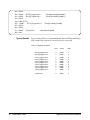
Introduction . . . . . . . . . . . . . . . . .
Command Module Configuration . . . . .
Factory Settings . . . . . . . . . . . . .
Some Command Module Definitions . .
Command Module Self-Tests . . . . . . . .
Test S-1: GPIB Power-On Test . . . . . .
Test S-2: RS-232 Power-On Self-Test . .
Functional Verification Tests . . . . . . . .
Test F-1: Front Panel Outputs . . . . . .
Test F-2: General System Information . .
Test F-3: Hierarchy/Device Information .
Test F-4: Table/Memory Information . .
Test F-5: Interrupt/Status Information . .
Test F-6: Triggering Information . . . . .
Test F-7: Serial Port Information . . . . .
.
.
.
.
.
.
.
.
.
.
.
.
.
.
.
.
.
.
.
.
.
.
.
.
.
.
.
.
.
.
. . . .
. . . .
. . . .
. . . .
. . . .
. . . . .
. . . . .
. . . .
. . . . .
. . . . .
. . . . .
. . . . .
. . . . .
. . . . .
. . . . .
.
.
.
.
.
.
.
.
.
.
.
.
.
.
.
.
.
.
.
.
.
.
.
.
.
.
.
.
.
.
. . . .
. . . .
. . . .
. . . .
. . . .
. . . . .
. . . . .
. . . .
. . . . .
. . . . .
. . . . .
. . . . .
. . . . .
. . . . .
. . . . .
17
18
18
20
22
22
24
27
28
32
34
40
45
48
51
Chapter 2 - Verification Tests
Agilent E1406A Service Manual
1
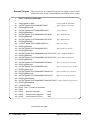
Chapter 3 - Replaceable Parts
Introduction . . . . . .
Exchange Modules . .
Replaceable Parts Lists
Component Locators .
.
.
.
.
.
.
.
.
.
.
.
.
.
.
.
.
.
.
.
.
.
.
.
.
.
.
.
.
.
.
.
.
.
.
.
.
.
.
.
.
.
.
.
.
.
.
.
.
.
.
.
.
.
.
.
.
.
.
.
.
.
.
.
.
.
.
.
.
.
.
.
.
.
.
.
.
.
.
.
.
.
.
.
.
.
.
.
.
.
.
.
.
55
55
55
57
Introduction . . . . . . . . . . . . .
Repair Strategy . . . . . . . . . . .
Troubleshooting . . . . . . . . . .
Assembly/Disassembly Instructions
Repair/Maintenance Guidelines . .
ESD Precautions . . . . . . . . .
Soldering Printed Circuit Boards
Post-Repair Safety Checks . . .
Returning an Agilent E1406A . . . .
.
.
.
.
.
.
.
.
.
.
.
.
.
.
.
.
.
.
.
.
.
.
.
.
.
.
.
.
.
.
.
.
.
.
.
.
.
.
.
.
.
.
.
.
.
.
.
.
.
.
.
.
.
.
.
.
.
.
.
.
.
.
.
.
.
.
.
.
.
.
.
.
.
.
.
.
.
.
.
.
.
.
.
.
.
.
.
.
.
.
.
.
.
.
.
.
.
.
.
.
.
.
.
.
.
.
.
.
.
.
.
.
.
.
.
.
.
.
.
.
.
.
.
.
.
.
.
.
.
.
.
.
.
.
.
.
.
.
.
.
.
.
.
.
61
61
62
66
71
71
71
72
73
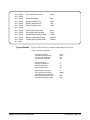
Chapter 4 - Service
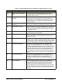
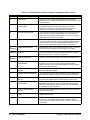
Chapter 5 - Error Messages
Introduction . . . . . . . . . . . . . . . . . . . . . . . . . . . . . 75
Error Message Types . . . . . . . . . . . . . . . . . . . . . . 75
Configuration Errors . . . . . . . . . . . . . . . . . . . . . . . 76
Appendix A - Verification Tests - C Programs
Introduction . . . . . . . . . . . . . . . . . . . . . . . . . . . . . 93
2
Agilent E1406A Service Manual
Certification
Agilent Technologies certifies that this product met its published specifications at the time of shipment from the factory. Agilent
Technologies further certifies that its calibration measurements are traceable to the United States National Institute of Standards and
Technology (formerly National Bureau of Standards), to the extent allowed by that organization’s calibration facility, and to the calibration
facilities of other International Standards Organization members.
Warranty
This Agilent Technologies product is warranted against defects in materials and workmanship for a period of one (1) year from date of
shipment. Duration and conditions of warranty for this product may be superseded when the product is integrated into (becomes a part
of) other Agilent products. During the warranty period, Agilent Technologies will, at its option, either repair or replace products which
prove to be defective.
For warranty service or repair, this product must be returned to a service facility designated by Agilent Technologies. Buyer shall prepay
shipping charges to Agilent and Agilent shall pay shipping charges to return the product to Buyer. However, Buyer shall pay all shipping
charges, duties, and taxes for products returned to Agilent from another country.
Agilent warrants that its software and firmware designated by Agilent for use with a product will execute its programming instructions
when properly installed on that product. Agilent does not warrant that the operation of the product, or software, or firmware will be
uninterrupted or error free.
Limitation Of Warranty
The foregoing warranty shall not apply to defects resulting from improper or inadequate maintenance by Buyer, Buyer-supplied products
or interfacing, unauthorized modification or misuse, operation outside of the environmental specifications for the product, or improper site
preparation or maintenance.
The design and implementation of any circuit on this product is the sole responsibility of the Buyer. Agilent does not warrant the Buyer’s
circuitry or malfunctions of Agilent products that result from the Buyer’s circuitry. In addition, Agilent does not warrant any damage that
occurs as a result of the Buyer’s circuit or any defects that result from Buyer-supplied products.
NO OTHER WARRANTY IS EXPRESSED OR IMPLIED. Agilent SPECIFICALLY DISCLAIMS THE IMPLIED WARRANTIES
OF MERCHANTABILITY AND FITNESS FOR A PARTICULAR PURPOSE.
Exclusive Remedies
THE REMEDIES PROVIDED HEREIN ARE BUYER’S SOLE AND EXCLUSIVE REMEDIES. Agilent SHALL NOT BE LIABLE
FOR ANY DIRECT, INDIRECT, SPECIAL, INCIDENTAL, OR CONSEQUENTIAL DAMAGES, WHETHER BASED ON CONTRACT, TORT, OR ANY OTHER LEGAL THEORY.
Notice
The information contained in this document is subject to change without notice. Agilent Technologies MAKES NO WARRANTY OF
ANY KIND WITH REGARD TO THIS MATERIAL, INCLUDING, BUT NOT LIMITED TO, THE IMPLIED WARRANTIES OF
MERCHANTABILITY AND FITNESS FOR A PARTICULAR PURPOSE. Agilent shall not be liable for errors contained herein or for
incidental or consequential damages in connection with the furnishing, performance or use of this material. This document contains
proprietary information which is protected by copyright. All rights are reserved. No part of this document may be photocopied, reproduced,
or translated to another language without the prior written consent of Agilent Technologies, Inc. Agilent assumes no responsibility for the
use or reliability of its software on equipment that is not furnished by Agilent.
U.S. Government Restricted Rights
The Software and Documentation have been developed entirely at private expense. They are delivered and licensed as "commercial
computer software" as defined in DFARS 252.227- 7013 (Oct 1988), DFARS 252.211-7015 (May 1991) or DFARS 252.227-7014 (Jun
1995), as a "commercial item" as defined in FAR 2.101(a), or as "Restricted computer software" as defined in FAR 52.227-19 (Jun 1987)(or
any equivalent agency regulation or contract clause), whichever is applicable. You have only those rights provided for such Software and
Documentation by the applicable FAR or DFARS clause or the Agilent standard software agreement for the product involved.
Agilent E1406A Command Module User’s Manual
Edition 2 Rev 3
Copyright © 1996-2006 Agilent Technologies, Inc. All Rights Reserved.
Agilent E1406A Command Module User’s Manual
3
Printing History
The Printing History shown below lists all Editions and Updates of this manual and the printing date(s). The first printing of the manual
is Edition 1. The Edition number increments by 1 whenever the manual is revised. Updates, which are issued between Editions, contain
replacement pages to correct the current Edition of the manual. Updates are numbered sequentially starting with Update 1. When a new
Edition is created, it contains all the Update information for the previous Edition. Each new Edition or Update also includes a revised copy
of this printing history page. Many product updates or revisions do not require manual changes and, conversely, manual corrections may
be done without accompanying product changes. Therefore, do not expect a one-to-one correspondence between product updates and
manual updates.
Edition 1 (Part Number E1406-90010). . . . . . . . . . . . . . . . . . . . . . . . . June 1996
Edition 2 (Part Number E1406-90011). . . . . . . . . . . . . . . . . . . . . . . August 1996
Edition 2 Rev 2 (Part Number E1406-90011) . . . . . . . . . . . . . . September 2006
Edition 2 Rev 3 (Part Number E1406-90011) . . . . . . . . . . . . . September 2012
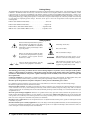
Safety Symbols
Instruction manual symbol affixed to product.
Indicates that the user must refer to the manual for specific WARNING or CAUTION
information to avoid personal injury or damage to the product.
Indicates the field wiring terminal that must
be connected to earth ground before operating
the equipment—protects against electrical
shock in case of fault.
or
Frame or chassis ground terminal—typically
connects to the equipment’s metal frame.
Alternating current (AC).
Direct current (DC).
Indicates hazardous voltages.
WARNING
CAUTION
Calls attention to a procedure, practice, or condition that could cause bodily injury or death.
Calls attention to a procedure, practice, or condition that could possibly cause damage to
equipment or permanent loss of data.
WARNINGS
The following general safety precautions must be observed during all phases of operation, service, and repair of this product.
Failure to comply with these precautions or with specific warnings elsewhere in this manual violates safety standards of design,
manufacture, and intended use of the product. Agilent Technologies assumes no liability for the customer’s failure to comply with
these requirements.
Ground the equipment: For Safety Class 1 equipment (equipment having a protective earth terminal), an uninterruptible safety earth
ground must be provided from the mains power source to the product input wiring terminals or supplied power cable.
DO NOT operate the product in an explosive atmosphere or in the presence of flammable gases or fumes.
For continued protection against fire, replace the line fuse(s) only with fuse(s) of the same voltage and current rating and type.
DO NOT use repaired fuses or short-circuited fuse holders.
Keep away from live circuits: Operating personnel must not remove equipment covers or shields. Procedures involving the removal of
covers or shields are for use by service-trained personnel only. Under certain conditions, dangerous voltages may exist even with the
equipment switched off. To avoid dangerous electrical shock, DO NOT perform procedures involving cover or shield removal unless you
are qualified to do so.
DO NOT operate damaged equipment: Whenever it is possible that the safety protection features built into this product have been
impaired, either through physical damage, excessive moisture, or any other reason, REMOVE POWER and do not use the product until
safe operation can be verified by service-trained personnel. If necessary, return the product to an Agilent Technologies Sales and Service
Office for service and repair to ensure that safety features are maintained.
DO NOT service or adjust alone: Do not attempt internal service or adjustment unless another person, capable of rendering first aid and
resuscitation, is present.
DO NOT substitute parts or modify equipment: Because of the danger of introducing additional hazards, do not install substitute parts
or perform any unauthorized modification to the product. Return the product to an Agilent Technologies Sales and Service Office for
service and repair to ensure that safety features are maintained.
4
Agilent E1406A Command Module User’s Manual
Declaration of Conformity
Declarations of Conformity for this product and for other Agilent products may be downloaded from the Internet. There are two methods to obtain
the Declaration of Conformity:
•
Go to http://regulations.corporate.agilent.com/DoC/search.htm . You can then search by product number to find the latest Declaration
of Conformity.
• Alternately, you can go to the product web page (www.agilent.com/find/E1406A), click on the Document Library tab then
scroll down until you find the Declaration of Conformity link.
Notes
6
Agilent E1406A Command Module User’s Manual
Notes
Agilent E1406A Command Module User’s Manual
7
Notes
8
Agilent E1406A Command Module User’s Manual
Chapter 1
General Information
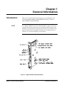
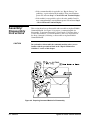
Introduction
NOTE
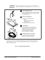
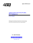
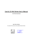
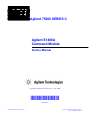
This service manual contains information to test, troubleshoot, and
repair the Agilent E1406A Command Module. Figure 1-1 shows a
typical E1406A Command Module.
See “Agilent 75000 Series C Service Documentation”, page 4, for a list of
manuals that describe mainframe and command module operation and
hardware. The information in this manual assumes you are familiar with
Agilent E1406A Command Module operation. If incoming inspection is
required, see “Inspection/Shipping” in this chapter.
GPIB
GPIB
GPIB
Figure 1-1. Agilent E1406A Command Module
Agilent E1406A Service Manual
General Information 9
Safety
Information
The Agilent E1406A Command Module is a Safety Class I instrument
that is provided with a protective earth terminal when installed in the
mainframe. Check the mainframe, command module, and all related
documentation for safety markings and instructions before operating or
servicing a command module.
See the WARNINGS page (page 4) for a summary of safety
information. Safety information to test and service the E1406A
Command Module follows and is also found throughout this manual.
WARNINGS
WARNING
Follow the WARNINGS listed to avoid possible injury to yourself or
others when operating, repairing, or servicing an Agilent E1406A
Command Module.
SERVICE-TRAINED PERSONNEL ONLY. The information in this
manual is for service-trained personnel who are familiar with
electronic circuitry and are aware of the hazards involved. To
avoid personal injury or damage to the instrument, do not
perform procedures in this manual or do any servicing unless
you are qualified to do so.
CHECK MAINFRAME POWER SETTINGS. Before applying
power, verify that the mainframe setting matches the line
voltage and the correct fuse is installed. An uninterruptible
safety earth ground must be provided from the main power
source to the supplied power cord set.
GROUNDING REQUIREMENTS. Interruption of the protective
(grounding) conductor (inside or outside the mainframe) or
disconnecting the protective earth terminal will cause a potential
shock hazard that could result in personal injury. (Grounding
one conductor of a two-conductor outlet is not sufficient
protection.)
IMPAIRED PROTECTION. Whenever it is likely that instrument
protection has been impaired, the mainframe must be made
inoperative and be secured against any unintended operation.
REMOVE POWER IF POSSIBLE. Some procedures in this
manual may be performed with power supplied to the mainframe
while protective covers are removed. Energy available at many
points may, if contacted, result in personal injury. (If service can
be performed without power applied, remove the power.)
10 General Information
Agilent E1406A Service Manual
WARNING
USING AUTOTRANSFORMERS. If the mainframe is to be
energized via an autotransformer (for voltage reduction) make
sure the common terminal is connected to neutral (that is, the
grounded side of the main’s supply).
USE PROPER FUSES. For continued protection against fire
hazard, replace the line fuse(s) only with fuses of the same
current rating and type (such as normal blow, time delay, etc.).
Do not use repaired fuses or short-circuited fuseholders.
CAUTIONS
CAUTION
Follow the CAUTIONS listed to avoid possible damage to the
equipment when performing instrument operation, service, or repair.
MAXIMUM FRONT PANEL INPUTS. Maximum input to the Clk In
port is ± 42.5 Vp-p (TTL or low level AC). Minimum input to the Clk
In port is ± 40 mVp-p. Maximum input to the Trig In port is 12.5 MHz
(TTL) or 40 MHz (ECL). Minimum pulse width for the input is 30
nsec (TTL) or 12.5 nsec (ECL).
STATIC ELECTRICITY. Static electricity is a major cause of
component failure. To prevent damage to the electrical components in
the command module, observe anti-static techniques when removing a
command module from the mainframe or when working on a command
module. Also, be sure to tighten the front panel screws when installing
a command module in a mainframe slot.
Product
Information
Specifications
This section lists Agilent E1406A Command Module:
•
•
•
•
•
•
specifications
serial number information
options
upgrades
environmental limits
recommended test equipment
See Appendix A - Specifications in the Agilent E1406A Command
Module User’s Manual for command module specifications.
Agilent E1406A Service Manual
General Information 11
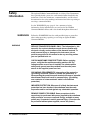
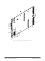
Serial Numbers
Figure 1-2 shows Agilent Technologies serial number structure. Agilent
E1406A Command Modules covered by this manual are identified by
the serial number prefixes listed on the title page.
Figure 1-2. Agilent Technologies Serial Numbers
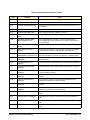
Options
Table 1-1 shows the options for the Agilent E1406A Command Module.
The Agilent E1406A Command Module can be upgraded. See the next
section “Upgrades” for information.
Table 1-1. Agilent E1406A Command Module Options
Model
Agilent
E1406A
Description
standard
with Expanded Memory
with IBASIC*
Option
--010
020
* IBASIC = Instrument BASIC
Upgrades
Table 1-2 shows available upgrade paths for the Agilent E1406A
Command Module and the upgrade kit(s) required. You can order the
upgrade kits from your nearest Agilent Technologies Sales and Support
Office. (A list of these offices is at the back of this manual.)
Table 1-2. Agilent E1406A Upgrades
Kit
12 General Information
Part Number
Expanded Memory
E1406-80010
IBASIC
E1406-80020
Agilent E1406A Service Manual
Operating/Storage
Environments
The Command Module should be stored in a clean, dry environment.
See Table 1-3 for recommended command module operating/storage
environments.
Table 1-3. Agilent E1406A Command Module Environments
Temperature
Relative Humidity
Operating Environment
0oC to + 55oC
< 65% (0 oC to + 40oC)
Storage/Shipment
-40oC to + 75oC
< 65% (0oC to + 40oC)
Recommended
Test Equipment
See Table 1-4 for test equipment recommended to test and service the
command module. Essential requirements for each piece of test
equipment are listed in the Requirements column. You may substitute
other equipment if it meets the requirements in Table 1-4.
Table 1-4. Agilent E1406A Command Module Recommended Test Equipment
Instrument
Requirements
Recommended
Model
Use*
Controller,
GPIB
GPIB compatibility as defined by IEEE
Standard 488-1987 and the identical
ANSI Standard MC1.1: SH1, AH1, T2,
TE0, L2, LE0, SR0, RL0, PP0, DC0, DT0,
and C1, 2, 3, 4, 5
HP 9000 Series 300
or
IBM Compatible PC
with BASIC
F,T
Mainframe
Compatible with Agilent E1406A
Agilent E1400B/T,
E1421A/B
F,T
Digital
Multimeter
Voltage Range: ± 10 VDC
Current Range: ± 20 mA DC
Agilent 3458A
T
Digitizing
Oscilloscope
Vertical Sensitivity: 1V/div
Vertical input: 5V
Agilent 54111D or
Agilent 54123T
F,T
* F = Functional Verification Tests, T = Troubleshooting
Inspection/
Shipping
Initial
Inspection
This section shows initial (incoming) inspection and shipping guidelines
for the Agilent E1406A Command Module.
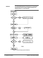
Use the steps in Figure 1-3 as guidelines to perform initial (incoming)
inspection of the command module.
Agilent E1406A Service Manual
General Information 13
WARNING
To avoid possible hazardous electrical shock, do not perform
electrical tests if there are signs of shipping damage to the
shipping container or to the instrument.
Notify Agilent and carrier.
Notify Agilent
Return Command Module to Agilent
Figure 1-3. Initial (Incoming) Inspection Guidelines
14 General Information
Agilent E1406A Service Manual
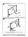
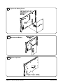
Shipping
Guidelines
Follow the steps in Figure 1-4 to return the command module to an
Agilent Technologies Sales and Support Office or to a Service Center.
1
Remove Cables/Connectors
• Remove GPIB/RS-232 cables from command module
• Remove cables/connectors from command module
front panel connectors
2
Prepare Command Module
• Attach tag to module that identifies
- owner
- Model Number/Serial Number
- Service Required
• Place tagged device in anti-static bag
3
Package Module
• Place packaged module in shipping carton*
• Place 75 to 100 mm (3 to 4 inches) of shockabsorbing material around the module
• Seal the shipping carton securely
• Mark the shipping carton FRAGILE
4
Ship Module to Agilent Technologies
• Place address label on shipping carton
• Send carton to Agilent Technologies
* We recommend you use the same shipping materials as those used in factory packaging (available from
Agilent Technologies). For other (commercially-available) shipping materials, use a double-wall carton with
minimum 2.4 MPa (350 psi) test.
Figure 1-4. Packaging/Shipping Guidelines
Agilent E1406A Service Manual
General Information 15
16 General Information
Agilent E1406A Service Manual
Chapter 2
Verification Tests
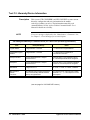
Introduction
WARNING
This chapter describes Agilent E1406A Command Module self-tests and
functional verification tests. There are no operation verification tests,
performance verification tests, or user adjustments for the command
module. Table 2-1 defines command module self-tests and functional
verification tests and suggests when to use each type of test.
Do not perform any of the verification tests in this chapter
unless you are a qualified, service-trained person and have
read the WARNINGS and CAUTIONS in Chapter 1.
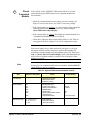
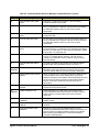
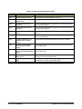
Table 2-1. Agilent E1406A Command Module Test Definitions
Title
Description
When to Use:
Self-Tests
Use power-on self-tests to verify that
the command module is operational
and is communicating with the
computer.
When you want to verify
operation and/or
communication.
Functional
Verification
Tests
Gives a high probability that the
command module is functional. These
tests provide a PASS/FAIL result.
At incoming inspection,
after module repair, or
whenever faulty operation
is suspected.
The test administrator must know command module and test equipment
operation. It is assumed that a qualified, service-trained person will connect
cables and adaptors required. See Table 1-4, Agilent E1406A Command
Module Recommended Test Equipment, for test equipment requirements.
Agilent E1406A Service Manual
Verification Tests 17
Command
Module
Configuration
NOTE
This section shows how to set an Agilent E1406A Command Module for
factory settings, and summarizes basic command module functions. See the
C-Size VXIbus Systems Configuration Guide for information on changing
command module switch settings.
This section shows system configuration based on command module switch
settings. These settings can be overridden by configuration tables stored in
the command module. See the Agilent E1406A Command Module User’s
Manual for details.
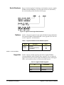
Factory Settings
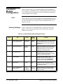
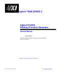
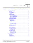
Table 2-2 shows how the command module is configured at the factory.
Figure 2-1 shows the switch positions and locations for the command
module factory settings.
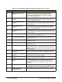
Table 2-2. Command Module Switch Settings/Functions
Switch
Title
Range
1
(VME) System Controller
Slot 0 Enable/Disable
Enabled (0)/
Disabled (1)
Enabled
Enabled
When the (VME) System Controller and Slot
0 Enable/Disable switches are enabled, the
command module functions as the system’s
Slot 0 device.
2
System Clock Source
Internal/
External
Internal
With Internal setting, the command module
supplies the 10 MHz system clock (CLK10).
With External setting, the clock must be
supplied from an external source.
3
Bus Request Level
0-3
3
Setting Bus Request Level 3 gives the
command module highest priority to request
the use of the Data Transfer Bus.
4
Logical Address
0 - 240
00
Identifies the logical address of the
command module. The secondary address
of the command module is ALWAYS 00,
regardless of the logical address setting.
5
Servant Area
1 - 255
255
Identifies the range of sequential logical
addresses of the modules to be controlled by
the command module.
6
Primary GPIB Address
GPIB Controller
0 - 30
Enabled (1)/
Disabled (0)
09
Disabled
Identifies GPIB port on command module.
Determines if command module is GPIB
System Controller.
18 Verification Tests
Factory
Setting
Function
Agilent E1406A Service Manual
Primary GPIB Adress:
GPIB
Address
GPIB
Figure 2-1. Command Module Switches - Factory Settings
NOTE: Be sure switches are COMPLETELY seated in the proper position. Switches may appear to be
in the correct position but may not be fully seated. One way to ensure that switches are seated
is to listen for a “click” as you depress the switch.
Agilent E1406A Service Manual
Verification Tests 19
Some Command
Module Definitions
Resource Manager/
Slot 0 Device
In this manual, the VXIbus “ system” assumed is an external controller
connected to a command module via GPIB, with the command module
configured as the resource manager and the slot 0 device. The following
paragraphs summarize some terms associated with the command module.
See the C-Size VXIbus Systems Configuration Guide for details.
Every VXIbus system must have a device to provide the system’s resource
manager and slot 0 requirements. The resource manager operates ONLY
at power-on. Once the power-on sequence completes, the resource manager
is no longer used. The resource manager:
•
•
•
•
•
identifies all installed plug-in modules
sets commander/servant hierarchies
performs A24/A32 mapping
allocates interrupt lines
starts system operation
During operation, the slot 0 function is used to:
• identify module locations
• manage the data flow across backplane buses
• provide the (10 MHz) system clock.
NOTE
Logical Address/
GPIB Address
In VXIbus systems using an external controller, the Agilent E1406A
Command Module should be configured as resource manager and slot 0
device.
For VXIbus systems, the Logical Address (set with the Logical Address
Switch) is used to:
•
•
•
•
•
determine device registers base address
set a device as the system resource manager
establish servant areas
create instruments
derive secondary GPIB addresses
The GPIB (IEEE-488) Address is used to address the device and consists
of the following three parts:
• Interface Select Code (ISC) (typically 7)
• Primary GPIB address (set with the GPIB Address switch)
• Secondary GPIB address (derived from the Logical Address)
20 Verification Tests
Agilent E1406A Service Manual
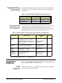
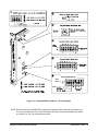
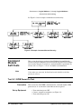
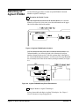
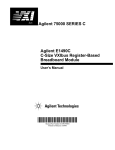
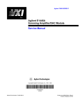
Instruments are located by the GPIB address. For example, Figure 2-2
shows a typical GPIB Address. The GPIB Primary Address is set with the
GPIB Address switch (switch 6 in Figure 2-1). However, the GPIB
Secondary Address is derived from the Logical Address switch setting
using the relationship:
GPIB Secondary Address = Logical Address/8
Thus, in Figure 2-2, since Logical Address 64 is set (with the Logical
Address switch), the GPIB Secondary Address = 64/8 = 08. Note that there
are no switches to set the Secondary GPIB Address.
NOTES
The "divide logical address by 8" process to get the IEEE-488 secondary
address is the Agilent implementation of VXIbus addressing using the
Agilent E1406A command module. Other manufacturers may
use different methods.
The GPIB Secondary Address for the Agilent E1406A command module
is always 00, regardless of the logical address set.
GPIB
GPIB
GPIB
Figure 2-2. Example: GPIB Address vs Logical Address
Commander/
Servant Areas
In a VXIbus system, the servant area identifies the modules (servants) that
are controlled by other modules (commanders). The Logical Address
switch sets the command module as the resource manager and is used with
the command module Servant Area switch (Switch 5 in Figure 2-1) to
determine the servant area of the command module using:
Agilent E1406A Service Manual
Verification Tests 21
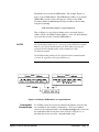
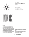
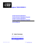
Servant area = (Logical Address +1) through (Logical Address +
Servant Area switch setting)
See Figure 2-3 for an example commander/servant hierarchy.
Figure 2-3. Example: Command/Servant Hierarchy
Command
Module
Self-Tests
Note
This section shows how to perform Agilent E1406A Command Module
self-tests using the GPIB power-on test and/or RS-232 power-on test. Either
test is usually adequate to verify that a command module is operational. If a
self-test fails, see Chapter 4 - Service for further tests/information.
Unless otherwise instructed, the Run/Load switch should be in the Run
position for all tests.
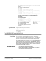
Test S-1: GPIB Power-On Test
Description
Set up Equipment
22 Verification Tests
This test uses the SYST:ERR? command for the command modules GPIB
power-on test. A “+0, No error” return indicates the test passed.
• Turn mainframe power OFF
• Connect computer to mainframe (see Figure 2-4)
• Turn mainframe power ON
Agilent E1406A Service Manual
NOTE
Refer to your computer’s documentation for information on connecting the
keyboard and video cables and other peripherals.
GPIB
GPIB
Figure 2-4. Test S-1: GPIB Power-On Test
Example Program
NOTE
This program performs an GPIB power-on test for the Agilent E1406A
command module and uses the SYST:ERR? command to check results. If
the power-on test passes, +0,"No error" is returned. If the power-on test
fails, the test returns an error message for each error detected. In this case,
see Chapter 5 - Error Messages for an explanation of the error(s)
If the Ready light does not turn on and/or the Failed/SYSFAIL lights stay lit
when power is turned ON, there is a very high probability that the command
module is defective. In this case, this test will probably not run, and you
should see Chapter 4 - Service for repair/replacement guidelines.
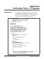
1! Test S-1: GPIB Power-On Self-Test
2
!
10 CLEAR SCREEN
20 ASSIGN @Addr to 70900
30 DIM Err_msg$[256]
40
50
Agilent E1406A Service Manual
PRINT “Test S-1: GPIB Power-On Self-Test”
PRINT
Verification Tests 23
60 PRINT “This test checks for power-on errors in the command
module.”
70 PRINT “To perform this test:”
80 PRINT
90 PRINT “ 1. Turn mainframe power OFF”
100 PRINT “ 2. Remove all modules (except command module)
from mainframe”
110 PRINT “ 3. Turn mainframe power ON”
120
130
140
150
160
170
180
190
200
210
PRINT “ 4. Wait at least 5 seconds before running the test.”
DISP “ Press Continue to run the GPIB power-on test ”
PAUSE
CLEAR SCREEN
PRINT “GPIB Power-On Self-Test”
REPEAT
OUTPUT @Addr;"SYST:ERR?"
!Query for system errors
ENTER @Addr;Err_msg$
!Enter results
PRINT Err_msg$
!Display results
UNTIL Err_msg$="+0,""No error"""
220 END
Typical Result
A typical result for no power-on errors is:
GPIB Power-on Self-Test
+0, “No error”
Test S-2: RS-232 Power-On Self-Test
Description
This test checks the command module power-on and configuration
sequence. The test requires an RS-232 terminal (such as an HP 700/94 or
equivalent) connected to the RS-232 terminal of the command module.
The command module power-on sequence can be monitored on an RS-232
terminal (or printer) that is connected to the command module’s RS-232
port. Pressing CTRL S on the terminal keyboard pauses the sequence, and
pressing CTRL Q resumes the sequence. Once the sequence is paused, it
remains paused until CTRL Q is pressed.
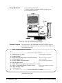
Set up Equipment
24 Verification Tests
• Turn mainframe and terminal power OFF
• Connect RS-232 terminal to command module (see Figure 2-5)
• Turn mainframe and terminal power ON
Agilent E1406A Service Manual
Figure 2-5. RS-232 Power-On Test
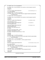
Typical Results
A typical power-on and configuration sequence for an Agilent E1406A
Command Module follows. If a configuration or start-up error occurs, such
as invalid address or failed self-test, the error is reported in the sequence.
See Chapter 5 - Error Messages for error messages.
Agilent E1406A Command Module
Typical Resource Manager Configuration Sequence
1
2
3
Testing ROM
Testing 512K Bytes RAM
Passed
CPU Self Test Passed
GPIB address: 09
Talk/Listen
Command Module ladd = 0
Command Module servant area = 255
Command Module VME bus timeout = ENABLED
Searching for static devices in mainframe 0
SC Device at ladd 0 in slot 0
Searching for dynamic devices
DC device in slot 12 moved to ladd 32, block size = 1
Searching for pseudo devices
Configuring Commander/Servant hierarchy
ladd = 0, cmdr ladd = -1
ladd = 8, cmdr ladd = 0
ladd = 16, cmdr ladd = 0
ladd = 32, cmdr ladd = 24
ladd = 64, cmdr ladd = 24
Agilent E1406A Service Manual
Verification Tests 25
3
Validating Commander/Servant hierarchy
Commander ladd 24 granted device ladd 32
Commander ladd 24 granted device ladd 64
4
Mapping A24 Memory
ladd 0, offset = 00200000H, size = 131072 (bytes)
ladd 24, offset = 00220000H, size = 131072 (bytes)
ladd 64, offset = 00240000H, size = 131072 (bytes)
Mapping A32 Memory
5
6
Configuring VME interrupts
VME interrupt line 1 assigned to ladd 0, handler ID 1
VME interrupt line 2 assigned to ladd 24, handler ID 1
VME interrupt line 3 assigned to ladd 64, handler ID 1
VME interrupt line 4 - no handler assigned
VME interrupt line 5 - no handler assigned
VME interrupt line 6 - no handler assigned
VME interrupt line 7 - no handler assigned
SYSTEM INSTALLED AT SECONDARY ADDR 0
VOLTMTR INSTALLED AT SECONDARY ADDR 1
SWITCH INSTALLED AT SECONDARY ADDR 2
MBinstr INSTALLED AT SECONDARY ADDR 3
SYSTEM instrument started
BNO issued to ladd 24, BNO response = FFFE
Opening GPIB access for message based device at sec addr 03
1
The Agilent E1406A operating system performs a series of self-tests and clears its volatile RAM. The
command module’s GPIB address, logical address, and servant area (based on the switch
settings) are reported.
2
The resource manager identifies all statically configured modules, then locates and configures
all dynamically configurable modules. The resource manager then searches for pseudo devices
(such as IBASIC).
3
The resource manager establishes the VXIbus system’s commander/servant hierarchies based
on the commander’s servant area and the servant’s logical address.
4
The resource manager allocated A24 addresses to access the memory located on the modules
at logical addresses 0, 24, and 64. Note that the offset is specified in hexadecimal and the size is
specified in bytes. For this particular system, there are no A32 devices.
5
The resource manager allocates interrupt lines to itself and to the other interrupt handlers in
the system.
6
The resource manager identifies the secondary GPIB addresses used in the system, starts the
SYSTEM instrument (the command module), issues the Begin Normal Operation (BNO) command
to its direct message based servant, and opens GPIB access to the module at secondary GPIB
address 03.
26 Verification Tests
Agilent E1406A Service Manual
Functional
Verification
Tests
This section describes functional verification tests for the Agilent E1406A
Command Module. These (optional) tests can be used to check specific
command module functions. Typically, functional verification tests are used
after repair or whenever command module operation is questionable. Table
2-3 lists functional verification tests for the command modules.
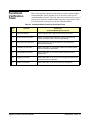
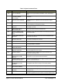
Table 2-3. Command Module Functional Verification Tests
Test
#
Test Title
Checks This
Command Module/System Function
F-1
Front Panel Outputs
Checks outputs from the Trig Out Port and the Clk Out Port.
F-2
General System Information
Returns command module addresses, number of devices in the
system, and system version, time, and date settings.
F-3
Hierarchy/Device Information
Returns hierarchy and static information for the module at the
selected logical address.
F-4
Table/Memory Information
Returns information on Configuration Tables and command module
memory including the Flash ROM.
F-5
Interrupt/Status Information
Returns information on command module interrupt lines and on
register status.
F-6
Triggering Information
Returns information on ECLTrg and TTLTrg trigger line settings and
on the Trig Out port configuration.
F-7
Serial Port Information
Returns information on the RS-232 serial port configuration.
Agilent E1406A Service Manual
Verification Tests 27
Test F-1: Front Panel Outputs
Description
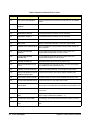
Part
Title
This test checks the output levels from the front panel Trig Out and Clk Out
ports. There are four parts to the test, as follows. See Figure 2-6 for a
summary of the trigger sources and paths for parts A, B, and C.
Description
A
INTernal Trigger
Source Test
For this test, the Trig Out port level should start at +5V, then go to 0V for two
seconds, and then go back to +5V.
B
TTL/ECL Trigger Line
Source Test
Checks the Trig Out port output using each TTLTrg and ECLTrg trigger line as a
trigger source. For each TTLTrg/ECLTrg trigger line, the Trig Out port level
should start at +5V, then go to 0V for two seconds, then go back to +5V.
C
Trig In Port Source
Test
Checks the Trig In and Trig Out ports on the command module, using the seven
TTLTrg and two ECLTrg lines (in turn) to check input/output. For each
TTLTrg/ECLTrg Trigger Line, the Trig Out Port level should start at +5V.
When a TTL signal is applied to the Trig In port, the Trig Out port level should go
to 0V and stay at 0V until the signal is removed from the Trig In port. Then, the
Trig Out Port level should return +5V.
D
10 MHz Clk Out Signal
Test
Checks the output from the Clk Out port on the command module front panel.
The oscilloscope display should be a 5V pp square wave at 10 MHz (period = 0.1
µsec).
Figure 2-6. Trig Out Port Level Tests
28 Verification Tests
Agilent E1406A Service Manual
•
•
•
•
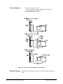
Set up Equipment
Turn mainframe power OFF
Connect oscilloscope to command module (see Figure 2-7)
Set up oscilloscope (see Figure 2-7)
Turn mainframe power ON
Figure 2-7. Test F-1: Front Panel Outputs Connections
Example Program
This program runs the three Trig Out tests and the Clk Out test described
above.
Agilent E1406A Service Manual
Verification Tests 29
1
2
10
20
30
40
50
60
70
80
90
100
110
120
130
140
150
160
170
180
190
200
210
220
230
240
250
260
270
280
290
300
310
320
330
340
350
360
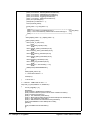
!Test F-1: Front Panel Outputs
!
ASSIGN @Addr to 70900
!Assign @Addr to cmd module
PRINT “Part A: INTernal Trigger Source Test”
PRINT
PRINT “Connect oscilloscope to command module Trig Out port”
DISP “ Press Continue when ready to run this test ”
PAUSE
OUTPUT @Addr;"OUTP:EXT:STAT ON"
!Enable Trig Out port configuration
OUTPUT @Addr;"OUTP:EXT:SOUR INT"
!Set Trig Out trigger source to INTernal
OUTPUT @Addr;"OUTP:EXT:LEV ON"
!Set Trig Out port level ON
WAIT 2
!Wait 2 seconds
OUTPUT @Addr;"OUTP:EXT:LEV OFF"
!Set Trig Out port level OFF
CLEAR SCREEN
PRINT “Part B: TTL/ECL Trigger Line Source Test”
PRINT
PRINT “Connect oscilloscope to command module Trig Out port”
DISP “ Press Continue when ready to run this test ”
PAUSE
CLEAR SCREEN
DIM Trg_sour$(9)[10]
DATA TTLT0,TTLT1,TTLT2,TTLT3,TTLT4
!TTLTrg trigger lines
DATA TTLT5,TTLT6,TTLT7,ECLT0,ECLT1
!TTLTrg/ECLTrg trigger lines
READ Trg_sour$(*)
!Read TTLTrg/ECLTrg trigger line data
FOR I=0 TO 9
PRINT TABXY(1,18),"Trigger line being tested is: “;Trg_sour$(I)
OUTPUT @Addr;"OUTP:"&Trg_sour$(I)&":STAT ON"
!Set TTLTrg/ECLTrg line STATE ON
OUTPUT @Addr;"OUTP:"&(Trg_sour$(I))&":SOUR INT" !Set TTLTrg/ECLTrg trig source to INT
OUTPUT @Addr;"OUTP:EXT:STAT ON"
!Enable Trig Out port configuration
OUTPUT @Addr;"OUTP:EXT:SOUR “;Trg_sour$(I)
!Allows Trig Out port to be driven by
selected TTLTrg/ECLTrg trigger line
OUTPUT @Addr;"OUTP:"&Trg_sour$(I)&":LEV ON"
!Set selected trigger line to ON
WAIT 2
!Wait 2 seconds
OUTPUT @Addr;"OUTP:"&Trg_sour$(I)&":LEV OFF"
!Set selected trigger line to OFF
DISP “ Press Continue to test next trigger line ”
PAUSE
CLEAR SCREEN
NEXT I
CLEAR SCREEN
(continued on next page)
30 Verification Tests
Agilent E1406A Service Manual
370
380
390
400
410
420
430
440
450
460
470
480
490
500
510
520
530
540
550
560
570
580
590
600
610
620
630
PRINT “Part C: Trig In Port Source Test”
PRINT
PRINT “Connect oscilloscope to command module Trig Out port”
DISP “ Press Continue when ready to run this test ”
PAUSE
CLEAR SCREEN
FOR I=0 TO 9
OUTPUT @Addr;"OUTP:"&Trg_sour$(I)&":STAT ON"
!Set TTLTrg/ECLTrg line STATE ON
OUTPUT @Addr;"OUTP:"&Trg_sour$(I)&":SOUR EXT" !Set selected TTLTrg/ECLTrg trigger
source to EXTernal (Trig In port)
OUTPUT @Addr;"OUTP:EXT:STAT ON"
!Enable Trig Out port configuration
OUTPUT @Addr;"OUTP:EXT:SOUR “;Trg_sour$(I)
!Drive Trig Out port with selected
TTLTrg/ECLTrg line
PRINT “Trigger line being tested is: ”;Trg_sour$(I)
PRINT
PRINT “1. Apply +5V TTL signal to Trig In Port. Trig Out level should go to 0V”
PRINT “2. Remove signal from Trig In Port. Trig Out level should go to +5V”
DISP “ When completed, press Continue to test next trigger line ”
PAUSE
CLEAR SCREEN
NEXT I
CLEAR SCREEN
PRINT “Part D: 10 MHz Clk Out Signal Test”
PRINT
PRINT “Connect oscilloscope to command module Clk Out port”
DISP “ Press Continue when ready to run this test ”
PAUSE
CLEAR SCREEN
END
Typical Results
See Figure 2-6 for oscilloscope displays for Trig Out port tests (Parts A, B,
and C). See Figure 2-8 for a typical display for the Clk Out port test (Part
D).
Figure 2-8. Typical Display - 10 MHz Clock Output
Agilent E1406A Service Manual
Verification Tests 31
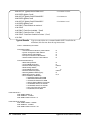
Test F-2: General System Information
Description
This test uses the following commands to return information on command
module addresses, number of devices in the system, and system version,
time, and date settings.
SYST:COMM:GPIB:ADDR?
VXI:CONF:DNUM?
VXI:CONF:LADD?
SYST:VERS?
SYST:DATE?
SYST:TIME?
Set up Equipment
Example Program
Command module GPIB address
Number of devices in the system
Device logical addresses
SCPI version for compliance
Current date setting
Current time setting
• Turn mainframe power OFF
• Connect computer to command module (see Figure 2-9)
• Turn mainframe power ON
This program returns the current settings for command module addresses,
number of devices in the system, and system version,
time, and date settings.
GPIB
GPIB
Figure 2-9. Test F-2. General System Information
32 Verification Tests
Agilent E1406A Service Manual
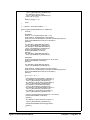
1 !Test F-2: General System Information
2 !
10 ASSIGN @Addr to 70900
20 DIM Ladds$[256]
30 OUTPUT @Addr;"SYST:COMM:GPIB:ADDR?"
40 ENTER @Addr;Cmd_addr
50 OUTPUT @Addr;"VXI:CONF:DNUM?"
60 ENTER @Addr;Dnum
70 OUTPUT @Addr;"VXI:CONF:LADD?"
80 ENTER @Addr;Ladds$
90 OUTPUT @Addr;"SYST:VERS?"
100 ENTER @Addr;Vers$
110 OUTPUT @Addr;"SYST:DATE?"
120 ENTER @Addr;Syst_date$
130 OUTPUT @Addr;"SYST:TIME?"
140 ENTER @Addr;Syst_time$
150 PRINT “Test F-2: General System Information”
160 PRINT
170 PRINT “ - Command module GPIB address
180 PRINT “ - Number of devices in the system
190 PRINT “ - Device logical addresses
200 PRINT “ - SCPI version for compliance
210 PRINT “ - Current date setting
220 PRINT “ - Current time setting
230 END
Typical Results
!Assign @Addr to cmd module
!Dimension Logical Address storage
!Query GPIB address
!Query number of modules installed
!Query device Logical Addresses
!Query version for SCPI compliance
!Query current date setting
!Query current time setting
”;Cmd_addr
”;Dnum
”;Ladds$
”;Vers$
”;Syst_date$
”;Syst_time$
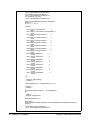
A typical result with ONLY an Agilent E1406A Command Module
installed in the mainframe follows. The date shown is 14 Jan 1993,
and the time shown is 13:52:20 (1:52:20 P.M.).
Test F-2: General System Information
- Command module GPIB address
- Number of devices in the system
- Device logical addresses
- SCPI version for compliance
- Current date setting
- Current time setting
Agilent E1406A Service Manual
9
1
+0
1990.0
+1993,+1,+14
+13,+52,+20
Verification Tests 33
Test F-3: Hierarchy/Device Information
Description
NOTE
This test uses VXI:CONF:HIER? and VXI:CONF:INF? to return current
hierarchy configuration and static information for the module
at the logical address you select. The information returned by each
command follows. See the Agilent E1406A Command Module User’s
Manual for details on each entry.
If an error message is displayed in the “Manufacturer’s Comments” line,
see Chapter 5 - Error Messages for error description.
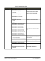
VXI:CONFigure:HIERarchy? Command returns (for a device at a specified logical address):
Item
Description/Range
Notes
Logical address
Integer between -1 and 255
-1 = device has no logical address
Commander’s logical
address
Integer between -1 and 255
-1 = device has no commander or
commander is unknown
Interrupt handlers
Comma-separated list of 7 integers
between 0 and 7
Interrupt lines 1-7 are mapped to returns.
0 = this interrupt handler is not configured.
Interrupters
Comma-separated list of 7 integers
between 0 and 7
Interrupt lines 1-7 are mapped to individual
returns. 0 = this interrupter not configured.
Pass/Failed
Integer from 0 to 3
0 = FAIL, 1 = IFAIL, 2 = PASS, 3 =READY
Manufacturer’s
specific
comments
80-character string containing instrument
name and secondary address UNLESS
start-up error(s) detected.
For start-up errors, return has form “CNFG
ERROR: n, m, ...,z”. See Chapter 5 for error
descriptions.
(see next page for VXI:CONF:INF? returns)
34 Verification Tests
Agilent E1406A Service Manual
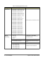
VXI:CONFigure:INFormation? Command returns (for a device at a specified logical address):
Item
Description/Range
Notes
Logical Address
Integer between -1 and 255
-1 = device has no logical address
Manufacturer ID
Integer between -1 and 4095
-1 = device has no Manufacturer ID
Model Code
Integer between -1 and 65535
-1 = device has no Model Code
Device Class
Integer between 0 and 5
0 = VXIbus memory device
1 = VXIbus extended device
2 = VXIbus message based device
3 = VXIbus register based device
4 = hybrid device
5 = Non-VXIbus device
Address Space
Integer from 0 to 15 (Integer value is sum
of binary weighted codes of the address
space occupied by device)
1 = device has A16 registers
2 = device has A24 registers
4 = device has A32 registers
8 = device has A64 registers
A16 Memory Offset
Integer between -1 and 65535
Base address for A16 registers on device.
-1 = device has no A16 memory
A24 Memory Offset
Integer between -1 and 16777215
Base address for A24 registers on device.
-1 = device has no A24 memory
A32 Memory Offset
Integer between -1 and 4294967295
Base address for A32 registers on device.
-1 = device has no A32 memory
A16 Memory Size
Integer between -1 and 65535
Number of bytes reserved for A16 registers.
-1 = device has no A24 memory
A24 Memory Size
Integer between -1 and 16777215
Number of bytes reserved for A24 registers.
-1 = device has no A16 memory
A32 Memory Size
Integer between -1 and 4294967295
Number of bytes reserved for A32 registers.
-1 = device has no A32 memory
Slot Number
Integer between -1 and the number of
slots in mainframe
-1 = slot that contains this device is unknown
Slot 0 Logical Address
Integer between -1 and 255
-1 = Slot 0 device associated with this
device is unknown
Subclass Register
Integer representing the subclass register
contents
-1 = Subclass register not defined for this
device
Attribute Register
Integer representing the attribute register
contents
-1 = Attribute register not defined for this
device
Manufacturer’s
specific
comments
80-character string containing instrument
name and secondary address UNLESS
start-up error(s) are detected.
For start-up errors, return has form “CNFG
ERROR: n, m, ...,z”. See Chapter 5 for error
descriptions.
Agilent E1406A Service Manual
Verification Tests 35
Set up Equipment
• Turn mainframe power OFF
• Connect computer to command module (see Figure 2-10)
• Turn mainframe power ON
GPIB
GPIB
Figure 2-10. Test F-3: Hierarchy Info Connections
Example Program
This program uses VXI:CONF:HIER? and VXI:CONF:INF? to return
current hierarchy configuration and static information for the module at the
logical address you select.
1 !Test F-3: Hierarchy/Device Information
2 !
3 !—————————————- Query system Logical Addresses ————————
10 ASSIGN @Addr TO 70900
!Assign @Addr to cmd module
20 CLEAR SCREEN
30 DIM Rinf$(16)[50],Hinf$(18)[50], Hier$[1000],Inf$[1000]
!Dimension storage variables
40 OUTPUT @Addr;"*RST"
!Reset cmd module
50 OUTPUT @Addr;"VXI:CONF:LADD?"
!Query system Logical Addresses
60 ENTER @Addr;Laddr$
70 PRINT TABXY(1,18),"System Logical Addresses are: “;Laddr$
80 INPUT “ Enter Logical Address of module to check.
!Select Logical Address for module
Then, press Continue. ”,Laddr
to be tested
90 CLEAR SCREEN
91
!————————————- Use VXI:CONF:HIER? Command———————-
(continued on next page)
36 Verification Tests
Agilent E1406A Service Manual
100
110
120
130
140
150
160
170
180
190
200
210
OUTPUT @Addr;"VXI:SEL “;VAL$(Laddr)
OUTPUT @Addr;"VXI:CONF:HIER?"
ENTER @Addr;Hier$
INTEGER Scn1,Fnd1
Scn1 =1
FOR I =1 TO 17 STEP Scn1
Fnd1 =POS(Hier$[Scn1],",")
Hinf$(I) =Hier$[Scn1;Fnd1-1]
Scn1 =Scn1+Fnd1
NEXT I
PRINT “VXI:CONF:HIER? Command Results”
PRINT
220
230
240
250
260
270
280
290
300
310
320
330
340
350
360
370
380
390
400
410
420
421
430
440
450
460
PRINT “ - Logical Address:
”;Hinf$(1)
PRINT “ - Commander’s Logical Address: ”;Hinf$(2)
PRINT “ - Interrupt Handler 1:
”;Hinf$(3)
PRINT “ - Interrupt Handler 2:
”;Hinf$(4)
PRINT “ - Interrupt Handler 3:
”;Hinf$(5)
PRINT “ - Interrupt Handler 4:
”;Hinf$(6)
PRINT “ - Interrupt Handler 5:
”;Hinf$(7)
PRINT “ - Interrupt Handler 6:
”;Hinf$(8)
PRINT “ - Interrupt Handler 7:
”;Hinf$(9)
PRINT “ - Interrupter 1:
”;Hinf$(10)
PRINT “ - Interrupter 2:
”;Hinf$(11)
PRINT “ - Interrupter 3:
”;Hinf$(12)
PRINT “ - Interrupter 4:
”;Hinf$(13)
PRINT “ - Interrupter 5:
”;Hinf$(14)
PRINT “ - Interrupter 6:
”;Hinf$(15)
PRINT “ - Interrupter 7:
”;Hinf$(16)
PRINT “ - Pass/Failed:
”;Hinf$(17)
PRINT “ - Manufacturer’s Comments: ”;Hier$[Scn1]
DISP “ Record results as desired. Then, press Continue for VXI:CONF:INF? results. ”
PAUSE
CLEAR SCREEN
! ———————-Use VXI:CONF:INF? Command —————
OUTPUT @Addr;"VXI:CONF:INF?"
!Query module at sel Logical Address
ENTER 70900;Inf$
INTEGER Scn,Fnd
Scn=1
!Use module at selected Logical Address
!Query module at sel Logical Address
!Loop to find individual values
(continued on next page)
Agilent E1406A Service Manual
Verification Tests 37
470
480
490
500
510
520
530
540
550
560
570
580
FOR I=1 TO 15 STEP Scn
Fnd=POS(Inf$[Scn],",")
Rinf$(I)=Inf$[Scn;Fnd-1]
Scn=Scn+Fnd
NEXT I
PRINT “VXI:CONF:INF? Command Results”
PRINT
PRINT “ - Logical Address:
”;Rinf$(1)
PRINT “ - Manufacturer ID:
”;Rinf$(2)
PRINT “ - Model Code:
”;Rinf$(3)
PRINT “ - Device Class:
”;Rinf$(4)
PRINT “ - Address Space:
”;Rinf$(5)
590
600
610
620
630
640
650
660
670
680
690
700
PRINT “
PRINT “
PRINT “
PRINT “
PRINT “
PRINT “
PRINT “
PRINT “
PRINT “
PRINT “
PRINT “
END
- A16 Memory Offset:
- A24 Memory Offset:
- A32 Memory Offset:
- A16 Memory Size:
- A24 Memory Size:
- A32 Memory Size:
- Slot Number:
- Slot 0 Logical Address:
- Subclass Register Contents:
- Attribute Register Contents:
- Manufacturer’s Comments:
!Loop to find individual values
”;Rinf$(6)
”;Rinf$(7)
”;Rinf$(8)
”;Rinf$(9)
”;Rinf$(10)
”;Rinf$(11)
”;Rinf$(12)
”;Rinf$(13)
”;Rinf$(14)
”;Rinf$(15)
”;Inf$[Scn]
Typical Results
The following tables show typical results for a command module at Logical
Address 0, with the command module being the only module installed in the
mainframe.
NOTE
If the information about the selected logical address is not available (i.e.,
the requested device is not in the mainframe or in the command module’s
servant area), Error -224 (“parameter error”) is set and no data is
returned.
Modules that are part of a combined instrument, such as a switchbox,
will return the same manufacturer’s comments as the first module in
the instrument. Other field information corresponds to the module at
the selected address.
38 Verification Tests
Agilent E1406A Service Manual
VXI:CONF:HIER? Command Results
- Logical Address:
- Commander’s Logical Address:
- Interrupt Handler 1:
- Interrupt Handler 2:
- Interrupt Handler 3:
- Interrupt Handler 4:
- Interrupt Handler 5:
- Interrupt Handler 6:
- Interrupt Handler 7:
- Interrupter 1:
- Interrupter 2:
- Interrupter 3:
- Interrupter 4:
- Interrupter 5:
- Interrupter 6:
- Interrupter 7:
- Pass/Failed:
- Manufacturer’s Comments:
+0
-1
(device has no commander)
+0
(handler is not configured)
+0
+0
+0
+0
+0
+0
+0
(interrupter is not configured)
+0
+0
+0
+0
+0
+0
+3
(READY)
"SYSTEM INSTALLED AT SECONDARY ADDR 0"
VXI:CONF:INF? Command Results
- Logical Address:
- Manufacturer ID:
- Model Code:
- Device Class:
- Address Space:
- A16 Memory Offset:
- A24 Memory Offset:
- A32 Memory Offset:
- A16 Memory Size:
- A24 Memory Size:
- A32 Memory Size:
- Slot Number:
- Slot 0 Logical Address:
- Subclass Register Contents:
- Attribute Register Contents:
- Manufacturer’s Comments:
Agilent E1406A Service Manual
+0
+4095
(Agilent Technologies is manufacturer)
+20
(20 =E1406 Command Module Code)
+2
(VXIbus message based device)
+3
(device has A16 and A24 registers)
-1
(device has no A16 memory)
+2097152
(A24 registers base address)
-1
(device has no A32 memory)
-1
(device has no A16 memory)
+131072
(number of bytes reserved for A24 registers)
-1
(device has no A32 memory)
+0
+0
-1
(subclass register not defined for this device)
-1
(attribute register not defined for this device)
"SYSTEM INSTALLED AT SECONDARY ADDR 0"
Verification Tests 39
Test F-4: Table/Memory Information
Description
This test uses the following commands to return information on command
module Configuration Table addresses and memory addresses/sizes. See
Chapter 2 in the Agilent E1406A Command Module User’s Manual for
Configuration Table definitions. See Chapter 5 in the Agilent E1406A
Command Module User’s Manual for command module memory
configuration.
Configuration Table Addresses
VXI:CONF:CTAB?
VXI:CONF:DCT?
VXI:CONF:ETAB?
VXI:CONF:ITAB?
VXI:CONF:MTAB?
Commander/Servant Hierarchy Table Address
Dynamic Configuration Table Address
Extender Device Table Address
Interrupt Line Allocation Table Address
A24/A32 Address Allocation Table Address
Command Module Memory Addresses/Sizes
DIAG:NRAM:ADDR?
DIAG:NRAM:CRE?
DIAG:NRAM:CRE? MAX
DIAG:RDIS:ADDR?
DIAG:RDIS:CRE?
DIAG:RDIS:CRE? MAX
DIAG:DRAM:AVA?
DIAG:DRAM:CRE?
DIAG:DRIV:LIST?
DIAG:FROM:AVA?
DIAG:FROM:SIZE?
DIAG:FROM:CRE?
Set Up Equipment
NRAM starting address
Current NRAM size (bytes)
Maximum NRAM size (bytes)
RDISK starting address
Current RDISK size (bytes)
Maximum RDISK size (bytes)
Remaining DRAM available (bytes)
DRAM size (bytes)/no. drivers
Drivers installed (in ROM/RAM)
Remaining Flash ROM available (bytes) for drivers
Determine size of flash ROM
Returns maximum number of drivers in a Flash ROM
• Turn Mainframe Power OFF
• Connect computer to Command Module (see Figure 2-11)
• Turn Mainframe Power ON
GPIB
GPIB
Figure 2-11. Test F-4: Table/Memory Info Connections
40 Verification Tests
Agilent E1406A Service Manual
Example Program
1
2
3
10
20
30
40
50
60
70
80
90
100
101
110
120
130
140
150
160
170
180
190
200
210
220
230
240
250
260
270
280
290
300
This program uses the commands listed in the Description section to return
information on Command Module Configuration Table addresses and
memory addresses/sizes.
!Test F-4: Table/Memory Information
!
! ————————- Get Configuration Table Information ————————————ASSIGN @Addr to 70900
!Assign @Addr to cmd module
DIM Dvr_list$[1000]
OUTPUT @Addr;"VXI:CONF:CTAB?"
!Cmdr/servant hierarchy table address
ENTER @Addr;Ctab$
OUTPUT @Addr;"VXI:CONF:DCT?"
!Dynamic Configuration Table address
ENTER @Addr;Dtab$
OUTPUT @Addr;"VXI:CONF:ETAB?"
!Extender Device Table address
ENTER @Addr;Etab$
OUTPUT @Addr;"VXI:CONF:ITAB?"
!Interrupt Line Allocation Table address
ENTER @Addr;Itab$
! —————————- Get Command Module Memory Information ——————————OUTPUT @Addr;"VXI:CONF:MTAB?"
!A24/A32 Address Alloc Table address
ENTER @Addr;Mtab$
OUTPUT @Addr;"DIAG:NRAM:ADDR?"
!NRAM starting address
ENTER @Addr;Nram_addr$
OUTPUT @Addr;"DIAG:NRAM:CRE?"
!Current NRAM size (bytes)
ENTER @Addr;Nram_cre$
OUTPUT @Addr;"DIAG:NRAM:CRE? MAX"
!Maximum NRAM size (bytes)
ENTER @Addr;Nram_max$
OUTPUT @Addr;"DIAG:RDIS:ADDR?"
!RDISK starting address
ENTER @Addr;Rdis_addr$
OUTPUT @Addr;"DIAG:RDIS:CRE?"
!Current RDISK size (bytes)
ENTER @Addr;Rdis_cre$
OUTPUT @Addr;"DIAG:RDIS:CRE? MAX"
!Maximum RDISK size (bytes)
ENTER @Addr;Rdis_max$
OUTPUT @Addr;"DIAG:DRAM:AVA?"
!Remaining DRAM available (bytes)
ENTER @Addr;Dram$
OUTPUT @Addr;"DIAG:DRAM:CRE?"
!Current DRAM size (bytes)/no. drivers
ENTER @Addr;Dram_cre$
OUTPUT @Addr;"DIAG:DRIV:LIST?"
!Drivers installed in ROM/RAM
ENTER @Addr;Dvr_list$
(continued on next page)
Agilent E1406A Service Manual
Verification Tests 41
301
310
320
330
340
350
360
370
380
390
400
410
!———————————— Display Results —————————————————PRINT “Test F-4: Table/Memory Information”
PRINT
PRINT “Configuration Tables”
PRINT
PRINT “ - Commander/Servant Hierarchy Table Address:
”;Ctab$
PRINT “ - Dynamic Configuration Table Address:
”;Dtab$
PRINT “ - Extender Device Table Address:
”;Etab$
PRINT “ - Interrupt Line Allocation Table Address:
”;Itab$
PRINT “ - A24/A32 Address Allocation Table Address:
”;Mtab$
PRINT
PRINT “Command Module Memory”
420 PRINT
430 PRINT “ - NRAM starting address:
”;Nram_addr$
440 PRINT “ - Current NRAM size (bytes):
”;Nram_cre$
450 PRINT “ - Maximum NRAM size (bytes):
”;Nram_max$
460 PRINT “ - RDISK starting address:
”;Rdis_addr$
470 PRINT “ - Current RDISK size (bytes):
”;Rdis_cre$
480 PRINT “ - Maximum RDISK size (bytes):
”;Rdis_max$
490 PRINT “ - Remaining DRAM avail (bytes):
”;Dram$
500 PRINT “ - DRAM size (bytes)/no. drivers:
”;Dram_cre$
510 PRINT “ - Drivers Installed (in ROM/RAM):”
520 INTEGER Scan,Found
530 Scan=1
540 REPEAT
550
Found=POS(Dvr_list$[Scan],";")
560
IF Found THEN
570
PRINT “ ->”;TAB(9);Dvr_list$[Scan;Found-1]
580
Scan=Scan+Found
590
ELSE
600
END IF
610 UNTIL NOT Found
620 PRINT “ ->”;TAB(9);Dvr_list$[Scan;Scan+50]
630 PRINT
640 PRINT
650 PRINT
660 PRINT “TESTING FLASH ROM”
670 PRINT
680 PRINT “Step 1. Turn OFF the mainframe.”
681 PRINT “Step 2. Put the Run/Load Switch on the Agilent E1406A Command Module
in the LOAD position.”
(continued on next page)
42 Verification Tests
Agilent E1406A Service Manual
682 PRINT “Step 3. Turn on the Mainframe.”
683 PRINT “Step 4. Press CONTINUE on the computer to continue program execution."
690 PAUSE
700 WAIT 5
710 OUTPUT @Addr;"DIAG:FROM:CRE 0"
! Set Flash ROM space to 0
720 CLEAR SCREEN
730 PRINT “Step 5. Turn OFF the mainframe.”
740 PRINT “Step 6. Put the Run/Load Switch on the Agilent E1406A Command Module
in the RUN position.”
750 PRINT “Step 7. Turn on the Mainframe.”
760 PRINT “Step 8. Press CONTINUE on the computer to continue program execution."
770 PAUSE
780 WAIT 5
790 OUTPUT @Addr;"DIAG:FROM:AVA?"
! Flash ROM Available
800 ENTER @Addr; Fava$
810 OUTPUT @Addr;"DIAG:FROM:SIZE?"
! Flash ROM Size
820 ENTER @Addr;Fsize$
830 OUTPUT @Addr;"DIAG:FROM:CRE?"
! Flash ROM Created
840 ENTER @Addr;Fcre$
850 PRINT “Flash ROM Space set to 0.”
860 PRINT
870 PRINT “Flash ROM Available: ”;Fava$
880 PRINT “Flash ROM Size: ”;Fsize$
890 PRINT “Flash ROM Created for Drivers: ”;Fcre$
900 PRINT
910 PRINT
920 PRINT “Step 9. Turn OFF the mainframe.”
930 PRINT “Step 10. Put the Run/Load Switch on the Agilent E1406A Command Module
in the LOAD position.”
940 PRINT “Step 11. Turn ON the Mainframe.”
950 PRINT “Step 12. Press CONTINUE to continue program execution.”
960 PAUSE
970 WAIT 5
980 OUTPUT @Addr;"DIAG:FROM:CRE 64"
! Set FLash ROM to Max for Drivers
990 CLEAR SCREEN
1000 PRINT “Step 5. Turn OFF the mainframe.”
1010 PRINT “Step 6. Put the Run/Load Switch on the Agilent E1406A Command Module
in the RUN position.”
1020 PRINT “Step 7. Turn ON the Mainframe.”
1030 PRINT “Step 8. Press CONTINUE to continue program execution.”
1040 PAUSE
1050 WAIT 5
(continued on next page)
Agilent E1406A Service Manual
Verification Tests 43
1060 OUTPUT @Addr;"DIAG:FROM:AVA?"
1070 ENTER @Addr; Fava$
1080 OUTPUT @Addr;"DIAG:FROM:SIZE?"
1090 ENTER @Addr;Fsize$
1100 OUTPUT @Addr;"DIAG:FROM:CRE?"
1110 ENTER @Addr;Fcre$
1120 PRINT “Flash ROM set to maximum”
1130 PRINT
1140 PRINT “Flash Rom Available: ”;Fava$
1150 PRINT “Flash Rom Size: ”;Fsize$
1160 PRINT “Flash Rom Created for Drivers: ”;Fcre$
1170 END
Typical Results
! Flash ROM Available
! Flash ROM Size
! Flash ROM Created
Typical results follow for a command module ONLY installed in the
mainframe (this does not show the step instructions).
Test F-4: Table/Memory Information
Configuration Tables
- Commander/Servant Hierarchy Table Address:
- Dynamic Configuration Table Address:
- Extender Device Table Address:
- Interrupt Line Allocation Table Address:
- A24/A32 Address Allocation Table Address:
Command Module Memory
- NRAM starting address:
- Current NRAM size (bytes):
- Maximum NRAM size (bytes):
- RDISK starting address:
- Current RDISK size (bytes):
- Maximum RDISK size (bytes):
- Remaining DRAM available (bytes):
- DRAM size (bytes)/no. drivers:
- Drivers installed (in ROM/RAM):*
-> SYSTEM,E1406A,A.09.00,ROM
-> UNKNOWN,UNKNOWN,0,ROM
-> VOLTMTR,E1326A,A.05.01,ROM
-> SWITCH,SWITCHBOX,A.07.00,ROM
-> COUNTER,E1332A,A.04.02,ROM
-> COUNTER,E1333A,A.04.02,ROM
-> DIG_I/O,E1330A,A.04.04,ROM
-> D/A,E1328A,A.04.02,ROM
+0
+0
+0
+0
+0
+0
+0
+485012
+0
+0
+485012
+0
+0,+0
Flash ROM set to 0
Flash ROM Available: +0
Flash ROM Size: +1048576
Flash ROM Created for Drivers: +0
Flash ROM set to maximum
Flash ROM Available: +1048576
Flash ROM Size: +1048576
Flash ROM Created for Drivers: +64
44 Verification Tests
Agilent E1406A Service Manual
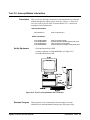
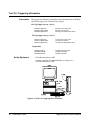
Test F-5: Interrupt/Status Information
Description
This test uses the following commands to return information on command
module interrupt lines and on register status. See Chapter 4 - Status and
Interrupts in the Agilent E1406A Command Module User’s Manual for
interrupt and status information.
Interrupt Information
DIAG:INT:SETn?
State of interrupt line n
Status Information
STAT:OPER:COND?
STAT:OPER:ENAB?
STAT:OPER:EVEN?
STAT:QUES:ENAB?
State of Condition register
Standard Operation Enable register mask value
Value of bit set in Event register
Questionable Status Register enable mask value
• Turn Mainframe Power OFF
Set Up Equipment
• Connect computer to Command Module (see Figure 2-12)
• Turn Mainframe Power ON
GPIB
GPIB
Figure 2-12. Test F-5: Interrupt/Status Info Connection
Example Program
This program uses the commands listed in Description to return
information on command module interrupt lines and register status.
Agilent E1406A Service Manual
Verification Tests 45
1
2
3
10
20
30
40
50
60
61
70
80
!Test F-5: Interrupt/Status Information
!
! ——————————————— Get Interrupt Information —————————ASSIGN @Addr to 70900
!Assign @Addr to cmd mod
DIM Int_set$(7)[3]
FOR I=1 TO 7
!Loop to find states of interrupt lines 1-7
OUTPUT @Addr;"DIAG:INT:SET"&VAL$(I)&"?"
!Query state of interrupt line n (n = 1-7)
ENTER @Addr;Int_set$(I)
NEXT I
! ——————————— Get Register Status Information ————-————OUTPUT @Addr;"STAT:OPER:COND?"
!Query state of Condition Register
ENTER @Addr;Oper_cond$
90
OUTPUT @Addr;"STAT:OPER:ENAB?"
100
110
120
130
ENTER @Addr;Oper_enab$
OUTPUT @Addr;"STAT:OPER:EVEN?"
ENTER @Addr;Oper_even$
OUTPUT @Addr;"STAT:QUES:ENAB?"
140
141
150
160
170
180
190
200
210
220
230
ENTER @Addr;Ques_enab$
!—————————————- Display Results ——————————————
PRINT “Test F-5: Interrupt/Status Information”
PRINT
PRINT “Interrupt Information”
PRINT
PRINT “ - State of interrupt line 1:
”;Int_set$(1)
PRINT “ - State of interrupt line 2:
”;Int_set$(2)
PRINT “ - State of interrupt line 3:
”;Int_set$(3)
PRINT “ - State of interrupt line 4:
”;Int_set$(4)
PRINT “ - State of interrupt line 5:
”;Int_set$(5)
240
250
PRINT “ - State of interrupt line 6:
PRINT “ - State of interrupt line 7:
260
270
PRINT
PRINT “Status Information”
280
290
300
310
320
330
PRINT
PRINT “
PRINT “
PRINT “
PRINT “
END
!Query Standard Operation Enable
register mask value
!Query value of bit set in Event register
!Query Questionable Status Register
enable mask value
”;Int_set$(6)
”;Int_set$(7)
- State of Condition register:
- Standard Operation Enable register mask value:
- Value of bit set in Event register:
- Questionable Status Register enable mask value:
46 Verification Tests
”;Oper_cond$
”;Oper_enab$
”;Oper_even$
”;Ques_enab$
Agilent E1406A Service Manual
Typical Results
Typical results follow for a command module with all interrupt lines OFF
and no status register values set.
Test F-5: Interrupt/Status Information
Interrupt Information
- State of interrupt line 1:
- State of interrupt line 2:
- State of interrupt line 3:
- State of interrupt line 4:
- State of interrupt line 5:
- State of interrupt line 6:
- State of interrupt line 7:
OFF
OFF
OFF
OFF
OFF
OFF
OFF
Status Information
- State of Condition register:
+0
- Standard Operation Enable register mask value: +0
- Value of bit set in Event register:
+0
- Questionable Status Register enable mask value: +0
Agilent E1406A Service Manual
Verification Tests 47
Test F-6: Triggering Information
Description
This test uses the following commands to return information on the ECLTrg
and TTLTrg trigger lines, and on the Trig Out port.
ECLTrg Trigger Lines (n = 0 or 1)
OUTP:ECLT[n]:LEV?
OUTP:ECLT[n]:SOUR?
OUTP:ECLT[n]:STAT?
ECLTrg Line n Logic Level
ECLTrg Line n Source
ECLTrg Line n State (ON or OFF)
TTLTrg Trigger Lines (n = 0 to 7)
OUTP:TTLT[n]:LEV?
OUTP:TTLT[n]:SOUR?
OUTP:TTLT[n]:STAT?
TTLTrg Line n Logic Level
TTLTrg Line n Source
TTLTrg Line n State (ON or OFF)
Trig Out Port
OUTP:EXT:LEV?
OUTP:EXT:SOUR?
OUTP:EXT:STAT?
Set Up Equipment
Trig Out Port Logic Level
Trig Out Port Source
Trig Out Port State
• Turn Mainframe Power OFF
• Connect computer to Command Module (see Figure 2-13)
• Turn Mainframe Power ON
GPIB
GPIB
Figure 2-13. Test F-6: Triggering Info Connections
48 Verification Tests
Agilent E1406A Service Manual
Example Program
This program uses the commands listed in the Description section to return
information on the ECLTrg and TTLTrg trigger lines, and on the Command
Module Trig Out port.
1
! Test F-6: Triggering Information
2
!
10
Assign @Addr to 70900
!Assign @Addr to Cmd Mod
20
DIM Elev$(2)[5],Esour$(2)[5],Estat$(2)[5]
30
DIM Tlev$(7)[5],Tsour$(7)[5],Tstat$(7)[5]
31
! ———————————————- Get TTLTrg Line Information —————————
40
FOR I=0 TO 1
50
OUTPUT @Addr;"OUTP:ECLT"&VAL$(I)&":LEV?"
!Query ECLTrg Line 0 - 1 logic level
60
ENTER @Addr;Elev$(I)
70
OUTPUT @Addr;"OUTP:ECLT"&VAL$(I)&":SOUR?" !Query ECLTrg Line 0 - 1 source
80
ENTER @Addr;Esour$(I)
90
OUTPUT @Addr;"OUTP:ECLT"&VAL$(I)&":STAT?"
!Query ECLTrg Line 0 - 1 state
100
ENTER @Addr;Estat$(I)
110 NEXT I
111 ! ——————————————- Get ECLTrg Line Information
————————————
120 FOR I=0 TO 7
130
OUTPUT @Addr;"OUTP:TTLT"&VAL$(I)&":LEV?"
!Query TTLTrg lines 0 - 7 logic level
140
ENTER @Addr;Tlev$(I)
150
OUTPUT @Addr;"OUTP:TTLT"&VAL$(I)&":SOUR?"
!Query TTLTrg lines 0 - 7 source
160
ENTER @Addr;Tsour$(I)
170
OUTPUT @Addr;"OUTP:TTLT"&VAL$(I)&":STAT?"
!Query TTLTrg lines 0 - 7 state
180
ENTER @Addr;Tstat$(I)
190 NEXT I
191 ! ——————————————- Get Trig Out Port Information
————————————
200 OUTPUT @Addr;"OUTP:EXT:LEV?"
!Query Trig Out port logic level
210
220
ENTER @Addr;Slev$
OUTPUT @Addr;"OUTP:EXT:SOUR?"
!Query Trig Out port source
230
240
ENTER @Addr;Ssour$
OUTPUT @Addr;"OUTP:EXT:STAT?"
!Query Trig Out port state
250 ENTER @Addr;Sstat$
251 ! ————————————————————- Display Information
——————-——————
260
270
280
PRINT “Test F-6: Triggering Information”
PRINT
PRINT “
Level Source State”
(continued on next page)
Agilent E1406A Service Manual
Verification Tests 49
290
300
310
320
330
340
350
360
370
380
PRINT
PRINT “ - ECLTrg Trigger Line 0:
”;Elev$(0),Esour$(0),Estat$(0)
PRINT “ - ECLTrg Trigger Line 1:
”;Elev$(1),Esour$(1),Estat$(1)
PRINT
FOR I=0 TO 7
PRINT “ - TTLTrg Trigger Line”;I;": “;Tlev$(I),Tsour$(I),Tstat$(I)
NEXT I
PRINT
PRINT “ - Trig Out Port:
”;Slev$,Ssour$,Sstat$
END
Typical Results
Typical results follow for a Command Module with all TTLTrg and ECLtrg
Lines and the Trig Out port set at level 0, no source, and state 0.
Test F-6: Triggering Information
50 Verification Tests
Level
Source
State
- ECLTrg Trigger Line 0:
- ECLTrg Trigger Line 1:
0
0
NONE
NONE
0
0
- TTLTrg Trigger Line 0:
- TTLTrg Trigger Line 1:
- TTLTrg Trigger Line 2:
- TTLTrg Trigger Line 3:
- TTLTrg Trigger Line 4:
- TTLTrg Trigger Line 5:
- TTLTrg Trigger Line 6:
- TTLTrg Trigger Line 7:
0
0
0
0
0
0
0
0
NONE
NONE
NONE
NONE
NONE
NONE
NONE
NONE
0
0
0
0
0
0
0
0
- Trig Out Port:
0
NONE
0
Agilent E1406A Service Manual
Test F-7: Serial Port Information
This test uses the following commands to return information on the
command module serial (RS-232) port.
Set Up Equipment
DIAG:COMM:SER:OWN?
SYST:COMM:SER:BAUD?
SYST:COMM:SER:CONT:DTR?
SYST:COMM:SER:CONT:RTS?
Serial port ownership
Baud rate
DTR mode line
RTS mode line
SYST:COMM:SER:BITS?
SYST:COMM:SER:SBIT?
SYST:COMM:SER:PACE:THR:STAR?
SYST:COMM:SER:PACE:THR:STOP?
Bits setting
Number of stop bits
STARt threshold level
STOP threshold level
SYST:COMM:SER:PAR:CHEC?
SYST:COMM:SER:PAR:TYP?
SYST:COMM:SER:TRAN:AUTO?
SYST:COMM:SER:PACE:PROT?
SYST:COMM:SER:TRAN:PACE:PROT?
Receive parity check
Parity type checking
Transmit/receive protocol
Receive pacing protocol
Transmit pacing protocol
• Turn Mainframe Power OFF
• Connect computer to Command Module (see Figure 2-14)
• Turn Mainframe Power ON
GPIB
GPIB
Figure 2-14. Test F-7: Serial Port Info Connections
Agilent E1406A Service Manual
Verification Tests 51
Example Program
This program uses the commands listed in the Description section to return
information on the current Command Module Serial (RS-232) Port settings.
1
!Test F-7: Serial Port Information
2
!
10
Assign @Addr to 70900
!Assign @Addr to cmd module
20
OUTPUT @Addr;"DIAG:COMM:SER:OWN?"
!Query serial port ownership
30
ENTER @Addr;Own$
40
OUTPUT @Addr;"SYST:COMM:SER:BAUD?"
! Query baud rate
50
ENTER @Addr;Baud
60
OUTPUT @Addr;"SYST:COMM:SER:CONT:DTR?"
!Query DTR mode line
70
ENTER @Addr;Dtr$
80
OUTPUT @Addr;"SYST:COMM:SER:CONT:RTS?"
!Query RTS mode line
90
ENTER @Addr;Rts$
100 OUTPUT @Addr;"SYST:COMM:SER:BITS?"
!Query bits setting
110 ENTER @Addr;Bits
120 OUTPUT @Addr;"SYST:COMM:SER:SBIT?"
!Query number of stop bits
130 ENTER @Addr;Sbits
140 OUTPUT @Addr;"SYST:COMM:SER:PACE:THR:STAR?" !Query STARt threshold level
150 ENTER @Addr;Star
160 OUTPUT @Addr;"SYST:COMM:SER:PACE:THR:STOP?" !Query STOP threshold level
170 ENTER @Addr;Stop
180 OUTPUT @Addr;"SYST:COMM:SER:PAR:CHEC?"
!Query receive parity check state
190 ENTER @Addr;Chec
200 OUTPUT @Addr;"SYST:COMM:SER:PAR?"
!Query current parity type checking
210 ENTER @Addr;Typ$
220 OUTPUT @Addr;"SYST:COMM:SER:TRAN:AUTO?"
!Query transmit/receive protocol
230 ENTER @Addr;Auto$
240 OUTPUT @Addr;"SYST:COMM:SER:PACE:PROT?"
!Query receive pacing protocol
250 ENTER @Addr;Rpace$
260 OUTPUT @Addr;"SYST:COMM:SER:TRAN:PACE:PROT?" !Query transmit pacing protocol
270 ENTER @Addr;Space$
280 CLEAR SCREEN
290 PRINT “Test F-7: Serial Port Information”
300 PRINT
310 PRINT “ - Serial port ownership:
”;Own$
320 PRINT “ - Transmit/receive baud rate:
”;Baud
330
PRINT “ - Current mode of DTR line:
”;Dtr$
(continued on next page)
52 Verification Tests
Agilent E1406A Service Manual
340
350
360
370
380
390
400
410
420
430
440
PRINT “
PRINT
PRINT “
PRINT “
PRINT “
PRINT “
PRINT
PRINT “
PRINT “
PRINT “
PRINT “
- Current mode of RTS line:
”;Rts$
- Current bits setting:
- Number of stop bits set:
- STARt Threshold Level:
- STOP Threshold Level:
”;Bits
”;Sbits
”;Star
”;Stop
- Receive parity check state:
- Current parity type checking:
- Transmit/receive pacing linkage:
- Receive pacing protocol state:
”;Chec
”;Typ$
”;Auto$
”;Rpace$
450
460
PRINT “ - Transmit pacing protocol state:
END
Typical Results
”;Space$
Typical results follow for a command module RS-232 serial port.
Test F-7: Serial Port Information
Agilent E1406A Service Manual
- Serial port ownership:
- Transmit/receive baud rate:
- Current mode of DTR line:
- Current mode of RTS line:
SYST
9600
ON
ON
- Current bits setting:
- Number of stop bits set:
- STARt threshold level:
- STOP threshold level:
8
1
10
65
- Receive parity check state:
- Current parity type checking:
- Transmit/receive pacing linkage:
- Receive pacing protocol state:
- Transmit pacing protocol state:
0
NONE
1
XON
XON
Verification Tests 53
54 Verification Tests
Agilent E1406A Service Manual
Chapter 3
Replaceable Parts
Introduction
This chapter contains information to order replaceable parts or
exchange modules for the Agilent E1406A Command Module. To
order a part or exchange assembly listed in this chapter, specify the
Agilent Technologies part number and the quantity required. Send the
order to your nearest Agilent Technologies Sales and Support Office.
Exchange
Modules
Table 3-1 lists modules that may be replaced on an exchange basis
(Exchange Modules). Exchange modules are available only on a trade-in
basis. Defective modules must be returned for credit. Order modules
for spare parts stock by the new module part number.
Table 3-1. Agilent E1406A Command Module - Exchange Modules
Model
E1406A
Replaceable
Parts Lists
NOTE
Description
Exchange Part
Number
New Part
Number
Replacement Module (Standard Memory)
E1406-69201
E1406-66201
Replacement Module (Expanded Memory)
E1406-69202
E1406-66202
Table 3-2 lists replaceable parts for the Agilent E1406A Command
Modules. See “Component Locators” (Figures 3-1 and 3-2) for
locations of parts in Table 3-2. Table 3-3 shows reference designators
for parts in Table 3-2, and Table 3-4 shows the manufacturer code list
for the parts.
If a command module defect can be traced to a fuse or replaceable
mechanical part, replace the fuse and/or part and retest the module.
If the defect cannot be traced to a fuse or replaceable mechanical part,
replace the entire module. Individual printed circuit assemblies (PCAs)
cannot be returned for replacement or exchange.
Agilent E1406A Service Manual
Replaceable Parts 55
Table 3-2. E1406A Command Module Replaceable Parts
Reference*
Designator
Agilent Part
Number
Qty
Description
Mfr* *
Code
Mfr Part
Number
REPLACEMENT MODULES
REPLACEMENT CONTROLLER MODULE (STANDARD)
REPLACEMENT CONTROLLER MODULE (EXP. MEMORY)
E1406-66201
E1406-66202
Agilent E1406A HARDWARE PARTS (Fig. 3-1)
BT1
E1300-86401
1
BATTERY PACK, 3.6V W/2
28480
E1300-86401
HDW1-HDW2
HDW3-HDW4
HDW5-HDW6
HDW7-HDW8
HDW9-HDW10
HDW11-HDW12
HDW13-HDW14
2190-0124
2950-0078
2190-0004
2190-0577
5180-6650
2190-0124
2950-0078
4
4
2
2
2
WASHER-LOCK INTL T NO. 10 .195-IN-ID
NUT-HEX-DBL-CHAM 10-32-THD .067-IN-THK
WASHER-LOCK INTL T NO. 4 .115-IN-ID
WASHER-LOCK NO. 10 .194-IN-ID .294-IN-OD
STANDOFF, HEX
WASHER-LOCK INTL T NO. 10 .195-IN-ID
NUT-HEX-DBL-CHAM 10-32-THD .067-IN-THK
98291
74163
78189
28480
28480
98291
74163
3002-26
500220
SF 1904-00
2190-0577
5180-6650
3002-26
500220
MP1
MP2
MP4-MP5
MP6-MP9
MP12
E1400-45102†
E1400-45101†
0380-1858
0380-1963
8160-0686
1
1
2
4
1
HANDLE - BOTTOM METAL INJECTION
HANDLE - TOP METAL INJECTION
STANDOFF-HEX .312-IN-LG 4-40-THD
STANDOFF-HEX 15-MM-LG M3.0 X 0.5-THD
RFI STRIP-FINGERS BE-CU TIN-PLATED
28480
28480
05791
05791
30817
E1400-84105
E1400-84106
ST9532-36
AL5172-15-21
00786-185
PNL1
E1406-00202†
1
FRONT PANEL-COMMAND MODULE
28480
E1406-00202
0515-1032
0515-1644
0515-1135
0515-1644
0515-0368†
2
4
4
2
SCREW-MACHINE M3 X 0.5
SCREW-MACHINE M3 X 0.5
SCREW-MACHINE M3 X 0.5
SCREW-MACHINE M3 X 0.5
SHOULDER SCREW ASS’Y
28480
28480
28480
28480
28480
0515-1032
0515-1644
0515-1135
0515-1644
0515-0368
1
1
SHIELD-TOP COMMAND MODULE
SHIELD-BOTTOM
28480
28480
E1406-00601
E1406-00602
SCR1-SCR2
SCR3-SCR4
SCR5-SCR8
SCR9-SCR10
SCR15-SCR16
SHD1
SHD2
E1406-00601
E1406-00602
14MM-LG FLAT-HEAD
12MM-LG FLAT-HEAD
25MM-LG FLAT-HEAD
12MM-LG FLAT-HEAD
Agilent E1406A A1 REPLACEABLE PARTS (Fig. 3-2)
F1-F3
F4
F5
2110-0712
2110-0699
2110-0712
4
1
FUSE-SUBMINATURE 4A 125V NTD AX
FUSE-SUBMINATURE 5A 125V NTD AX UL CSA
FUSE-SUBMINATURE 4A 125V NTD AX
75915
75915
75915
R251004T1
R251005T1
R251004T1
J1-J2
J5
J6
J7-J10
J11
J12
1251-7798
1251-4682
1252-1994
1250-2266
1252-2161
1252-3694
2
1
1
4
1
1
CONNECTOR-POST TYPE 2.54-PIN-SPCG 64 CONTACT
CONNECTOR-POST TYPE .100-PIN-SPCG 3 CONTACT
CONNECTOR-RECTANGLE D-SUBMIN 9-CKT 9-CONTACT
CONNECTOR-RF SMB PLUG 50-OHM
CONNECTOR-RECT. MICRO-RIBBON 24 CONTACT
CONNECTOR-POST TYPE .100-PIN-SPCG 2-CONTACT
81312
26742
00779
74970
00779
27264
64S-6033-04-31-2
1102-1-103-02
748879-1
131-3701-501
554923-2
705-45-0071
P1
P2
1252-1596
1252-4743
1
1
CONNECTOR-POST TYPE 2.54-PIN-SPCG 96-CONTACT
CONNECTOR-POST TYPE 2.54-PIN-SPCG 64-CONTACT
06776
00779
DIN-96CPC-SRI-TR
650945-5
S2
S3
3101-3187
3101-2673
1
1
SWITCH - DIP ROTARY 10 POS. BCD
SWITCH - DIP SLIDE SPDT 0.05A 30VDC
97525
81073
350012G5
78J01S
SP1
SP2-SP5
3101-2063
3101-3066
1
4
SWITCH-DIP ROCKER 4-1A 0.05A 30VDC
SWITCH-DIP ROCKER 8-1A 0.15A 30VDC
81073
81073
76YY23444S
76YY22968S
* See Table 3-3 for Reference Designator definitions
** See Table 3-4 for Code List of Manufacturers
† These parts are not compatible with older versions of the E1406A that have plastic handles. To replace one of these parts on an older
E1406A, you must order all four of the parts marked with a †.
56 Replaceable Parts
Agilent E1406A Service Manual
Table 3-3. Agilent E1406A Command Module Reference Designators
Agilent E1406A Command Module Reference Designators
A ............................. assembly
BT ...................... battery pack
F ..................................... fuse
HDW................misc hardware
J .........electrical connector (jack)
MP .................... misc. mech part
P ............... electrical conn (plug)
PNL .................................... panel
S ........................... switch (rotary)
SCR ................................... screw
SHD .................................. shield
SP ............. switch (push-button)
Table 3-4. Agilent E1406A Command Module Code List of Manufacturers
Mfr
Code
Manufacturer Name
Manufacturer Address
Zip
Code
00779
05791
06776
AMP INC
LYN-TRON INC
ROBINSON NUGENT INC
HARRISBURG
BURBANK
NEW ALBANY
PA US
CA US
IN US
17111
91505
47150
18873
26742
27264
DUPONT E I DE NEMOURS & CO
METHODE ELECTRONICS INC
MOLEX INC
WILMINGTON
CHICAGO
LISLE
DE US
IL
US
IL
US
19801
60656
60532
28480
30817
59730
AGILENT TECHNOLOGIES INC - CORPORATE
INSTRUMENT SPECIALTIES CO INC
THOMAS & BETTS CORP
PALO ALTO
CA US
DEL WATER GAP PA US
RARITAN
NJ US
94304
18327
08869
74163
74970
75915
PHELPS DODGE CORP
EF JOHNSON CO
LITTELFUSE INC
NEW YORK
WASECA
DES PLAINES
10022
56093
60016
76381
78189
81073
81312
3M CO
ILLINOIS TOOL WORK INC SHAKEPROOF
GRAYHILL INC
WINCHESTER ELECTRONICS
ST PAUL
ELGIN
LA GRANGE
OAKVILLE
MN
IL
IL
CT
US
US
US
US
55144
60126
60525
06779
83486
97525
98291
ELCO INDUSTRIES INC
EECO INC
ITT SEALECTRO CORP
ROCKFORD
SANTA ANA
TRUMBULL
IL US
CA US
CT US
61125
92702
06611
Component
Locators
NY US
MN US
IL US
Figures 3-1 and 3-2 show locations of selected replaceable parts for the
Agilent E1406A Command Module.
Agilent E1406A Service Manual
Replaceable Parts 57
Figure 3-1. Agilent E1406A Replaceable Parts
58 Replaceable Parts
Agilent E1406A Service Manual
Figure 3-2. Agilent E1406A A1 PCA Replaceable Parts
Agilent E1406A Service Manual
Replaceable Parts 59
60 Replaceable Parts
Agilent E1406A Service Manual
Chapter 4
Service
Introduction
This chapter contains information to service the Agilent E1406A Command
Module, including:
•
•
•
•
•
WARNING
recommended repair strategy
troubleshooting guidelines
assembly/disassembly instructions
repair/maintenance guidelines
returning module to Agilent Technologies
Do not perform any of the service procedures shown unless
you are a qualified, service-trained person, and have read the
WARNINGS and CAUTIONS in Chapter 1.
Equipment required for Agilent E1406A Command Module troubleshooting
and repair is listed in Table 1-4, Agilent E1406A Command Module
Recommended Test Equipment. Service notes and service literature for the
command modules may be available through Agilent Technologies.
Repair Strategy
The recommended repair strategy for the Agilent E1406A Command
Module is module replacement.
• Before replacing an Agilent E1406A Command Module, check fuses F1
through F5 on the A1 Printed Circuit Assembly (PCA) and/or the
replaceable mechanical parts listed in Table 3-2.
• If the fault can be traced to a fuse or replaceable mechanical part listed in
Table 3-2, repair the fault and retest the module.
If the fault cannot be traced to a fuse or replaceable mechanical part
listed in Table 3-2, replace the entire module.
• As required, re-download the IBASIC and/or the Device Drivers. See the
appropriate installation note for downloading device drivers or IBASIC.
NOTE
If you need to return a command module to Agilent Technologies, see
“Returning Modules to Agilent” at the end of this chapter.
Agilent E1406A Service Manual
Service 61
Troubleshooting
1
Prepare the
Mainframe
2
Check
LEDs and
Terminal Display
NOTE
This section shows suggested steps to troubleshoot Agilent E1406A
Command Module faults to a fuse on the A1 PCA or to a replaceable
mechanical part listed in Table 3-2. See Figure 4-1 for suggested steps.
To begin troubleshooting, turn the mainframe power switch OFF and
remove all power sources to any installed modules. Connect an RS-232
terminal to the front panel RS-232 port. See the C-Size VXIbus Systems
Configuration Guide for information on connecting and configuring an
RS-232 terminal.
Press the mainframe power switch ON and observe the four LEDs
on the command module front panel and the power-on display on the
RS-232 terminal. Then, wait at least 5 seconds before proceeding to
the next step (Step 3, Step 4, or Step 5).
The RS-232 terminal is a very valuable tool for use in power-on and
diagnostic troubleshooting, since it provides a “front panel” for the
command modules. See Chapter 3 - Using the Display Terminal Interface in
the Agilent E1406A Command Module User’s Manual for details on
RS-232 terminal operation and features.
For NORMAL power-on, the RS-232 terminal display shows:
• A kernel test that tests RAM, ROM, and the microprocessor,
monitors the ACFAIL* line and then calls the Resource Manager to
check the system.
• Resource Manager configuration/errors for the power-on sequence.
See “Test S-2: RS-232 Power-On Self-Test” in
Chapter 2 - Verification Tests for a typical power-on sequence.
For NORMAL power-on, the command module LED sequence is:
• Failed and SYSFAIL LEDs turn ON for 5 sec, then turn OFF
• Next, the Access light blinks ON at least once and turns OFF
• Then, the Ready LED turns ON and remains ON
Depending on the LED(s) that remain ON after 5 seconds, go to
Step 3 - Ready LED ON, Step 4 - Failed and SYSFAIL LEDs ON,
or Step 5 - Failed LED (ONLY) ON.
62 Service
Agilent E1406A Service Manual
Figure 4-1. E1406A Command Module Troubleshooting
Agilent E1406A Service Manual
Service 63
3
Ready LED
(ONLY) ON
When the “Ready” LED is ON, normal operation is indicated. However,
there may be configuration errors. If you have an RS-232 terminal
connected, check the terminal display for configuration errors (see Chapter
5 - Error Messages for code explanations).
If you do not have an RS-232 terminal connected, you can check
for configuration errors by sending the SYST:ERR? command to
the command module. See “Test S-1: GPIB Power-On Self-Test”
in Chapter 2 - Verification Tests for an example program.
• If +0, “No error” is returned, the system is normal and no
further action is required.
• If one or more configuration error messages are returned ,
see Chapter 5 - Error Messages for possible causes/corrections.
Correct configuration errors and exchange modules as required.
Replace module(s) as required, turn mainframe power ON and
rerun Step 2 - Check LEDs and Terminal Display.
4
Failed and
SYSFAIL
LEDs ON
NOTE
5
Failed LED
(ONLY) ON
The command module has failed the power-on self-test OR the module
could not complete initialization of one or more installed modules. Turn
mainframe power OFF and go to Step 6 - Check Command Module.
The SYSFAIL LED should never be ON by itself. The SYSFAIL LED does
NOT monitor the status of the backplane *SYSFAIL signal. If another device
pulls *SYSFAIL low, it will not turn on the SYSFAIL LED. The command
module will, however, perform a reboot/reset if *SYSFAIL goes low.
If only the Failed LED is ON after 5 seconds, one of the following
conditions has occurred. Turn mainframe power OFF and go to Step
6 - Check Command Module.
• The command module has FAILED the power-on self-test OR
• The command module has stopped working for some reason (e.g.,
no interrupt response from a register-based device even though the
device driver is present in the command module) OR
• The command module is a servant to another commander that is
asserting SYSFAIL INHIBIT in the command module’s Control
Register.
64 Service
Agilent E1406A Service Manual
6
Check
Command
Module
If the “Failed” and/or “SYSFAIL” LEDs remain ON after 5 seconds,
turn mainframe power OFF and remove the command module from
the mainframe.
• Check the command module switch settings for correct settings. See
Figure 2-1 for switch locations. See Table 4-1 for factory settings.
• If the switch settings are incorrect, set correct settings. Then, reinstall the
command module, turn mainframe power ON, and rerun Step 2 Check LEDs and Terminal Display.
• If the switch settings are correct, disassemble the command module. See
“Assembly/Disassembly Procedures” for details.
• Check fuses, and/or mechanical parts listed in Table 3-2. See Table 4-1
for suggested checks. See Figure 3-1 or 3-2 for component locations.
Note
If the switch settings, fuses, and/or mechanical parts appear to be good,
disconnect and then reconnect the battery connector. Reassemble and
reinstall the command module and turn mainframe power ON. Then, rerun
Step 2 - Check LEDs and Terminal Display. If the command module now
passes self-test and other modules are installed, check and replace other
modules as required.
Note
If you replace the command module with a new module, download IBASIC
and/or the device drivers as required.
Table 4-1. Agilent E1406A Command Module Checks
Area
Reference Designator
Check:
Heat Damage
-----
Discolored PC boards
Damaged Insulation
Evidence of arcing
Switch Settings
S2
S3
SP1
SP2
SP3
SP4
SP5
Bus Request Level
System Clock Setting
System Controller/Slot 0
LADDR Setting
Servant Area
Primary GPIB Address (GPIB
Controller OFF)
Configuration Switch
F1, F2, F3, F4, F5
J1, J2, J5 - J12
P1, P2
Fuse Continuity
Connector Contacts
Connector Contacts
Mechanical Parts
Agilent E1406A Service Manual
Factory Setting:
3
Internal
Enabled
0
255
09
0 (do not change)
Service 65
• If the command module is repairable (see “Repair Strategy” for
guidelines), repair and reinstall the module. Then, turn mainframe
power ON and rerun Step 2 - Check LEDs and Terminal Display.
• If the module is not repairable, replace the entire module. Install a
new command module, turn mainframe power ON and rerun Step 2
- Check LEDs and Terminal Display.
Assembly/
Disassembly
Instructions
CAUTION
This section shows how to disassemble and reassemble an Agilent E1406A
Command Module. See Figure 4-2 to prepare a command module for
disassembly. To perform disassembly, you will need a T-10 Torx driver, a
1/4-inch hex nut driver, a 9/32-inch nut driver, and a 3/16-inch nut driver.
See Steps 1 through 8 (following) to disassemble an Agilent E1406A
Command Module.
Do not handle or disassemble the command modules unless you are
familiar with the precautions listed in the “Repair/Maintenance
Guidelines” section of this chapter.
Figure 4-2. Preparing Command Module for Disassembly
66 Service
Agilent E1406A Service Manual
1
Loosen Front Panel Hardware
2
Remove Top Shield
3
Remove the Battery Connector
Agilent E1406A Service Manual
Service 67
4
Remove A2 Memory Board
5
Troubleshoot A1 PCA/Mechanical Parts
NOTE: Be sure switches are COMPLETELY seated in the proper position. Switches may appear to be
in the correct position but may not be fully seated. One way to ensure that switches are seated
is to listen for a “click” as you depress the switch.
68 Service
Agilent E1406A Service Manual
6
Replace A2 Memory Board
7
Reconnect the Battery
8
Replace Top Shield
Agilent E1406A Service Manual
Service 69
9
Replace Top Shield Screws
10
Tighten Front Panel Hardware
GPIB
70 Service
Agilent E1406A Service Manual
Repair/
Maintenance
Guidelines
Guidelines to repair and maintain an Agilent E1406A Command Module
follow, including:
CAUTION
Do not touch the command module edge connector pins at any time
unless you are actively using a static-free workstation.
ESD
Precautions
• ESD precautions
• Soldering printed circuit boards
• Post-repair safety checks
Electrostatic discharge (ESD) may damage CMOS and other static-sensitive
devices in the command modules such as ROM or RAM ICs. This damage
can range from slight parameter degradation to catastrophic failure. When
handling command modules, follow these guidelines to avoid damaging
components:
• Always use a static-free work station with a pad of
conductive rubber or similar material when handling
command module components.
• After you remove a module from the frame, place the module on a
conductive surface to guard against ESD damage.
• Do not use pliers to remove a CMOS device from a high-grip
socket. Instead, use a small screwdriver to pry the device up from
one end. Slowly lift the device up, one pair of pins at a time.
• After you remove a CMOS device from a module, place the device
onto a pad of conductive foam or other suitable holding material.
• If a device requires soldering, be sure the device is placed on a pad
of conductive material. Also, be sure you, the pad, and the soldering
iron tip are grounded to the device. Apply as little heat as possible
when soldering.
Soldering
Printed
Circuit Boards
CAUTION
The etched circuit boards on command module printed circuit assemblies
(PCAs) have plated-through holes that allow a solder path to both sides of
the insulating material. Soldering can be done from either side of the board
with equally good results. When soldering to any circuit board, keep in mind
the following guidelines:
Do not use a sharp metal object such as an awl or twist drill, since
sharp objects may damage the plated-through conductor.
Agilent E1406A Service Manual
Service 71
• Avoid unnecessary component unsoldering and soldering. Excessive
replacement can result in damage to the circuit board and/or adjacent
components.
• Do not use a high power (>30 watts) soldering iron on etched circuit
boards, as excessive heat may lift a conductor or damage the board.
• Use a suction device or wooden toothpick to remove solder from
component mounting holes. When using a suction device, be sure the
equipment is properly grounded to prevent electrostatic discharge from
damaging CMOS devices.
Post-Repair
Safety Checks
NOTE
72 Service
After making repairs to command module components, inspect the device
for any signs of abnormal internally generated heat, such as discolored
printed circuit boards or components, damaged insulation, or evidence of
arcing. Determine and correct the cause of the condition. Then, run the
power-on self-test to verify that the command module is operational.
As desired, you may want to run one or more of the functional verification
tests in Chapter 2 - Verification Tests.
Agilent E1406A Service Manual
Returning an
Agilent E1406A
Use the following procedures to return an Agilent E1406A Command
Module to Agilent Technologies.
1
Determine the Module Version
[a] If the model label is attached to the bottom shield of the command
module (see Figure 4-3 for location), note the model number on the upper
label of the bottom shield of the module.
Figure 4-3. Agilent E1406A Option Numbers
[b] If the model label has been removed from the bottom shield of the
command module, you will need to look at the A2 memory board part
number to determine the version. To do this, perform Steps 1 through 3 in
the “Command Modules Disassembly” section to remove the top shield and
the A2 memory board. Note the A2 memory board part number (see Figure
4-4).
Figure 4-4. Agilent E1406A Memory Board Part Numbers
2
Ship the Module to Agilent Technologies
Package the module and ship it to Agilent Technologies. See Chapter 1 General Information for packaging details.
Agilent E1406A Service Manual
Service 73
74 Service
Agilent E1406A Service Manual
Chapter 5
Error Messages
Introduction
This chapter shows how to read the Agilent E1406A Command
Modules error queue, and provides error message listings and probable
causes.
Error Message
Types
Table 5-1 shows the four categories of error messages for the Agilent
E1406A Command Modules. See the following tables for error message
descriptions:
•
•
•
•
Language Related Errors . . . . . . . . . . . . . . . .
Configuration Errors . . . . . . . . . . . . . . . . . . . .
System Instrument Errors . . . . . . . . . . . . . . . .
Operating System Errors. . . . . . . . . . . . . . . . .
Table 5-2
Table 5-3
Table 5-4
Table 5-5
Table 5-1. Agilent E1406A Command Modules Error Messages
Type/Error Numbers
Language Related Errors
(-100 to -499)
Description
Command Errors (-100 to -199):The instrument cannot understand or execute the
command.
Execution Errors (-200 to -299): The instrument is incapable of doing the action or
operation requested by a command.
Device-Specific Errors (-300 to -399): Indicates an instrument operation did not
complete, possibly due to an abnormal hardware or firmware condition.
Query Errors (-400 to -499): A problem has occurred in the instrument’s output queue.
Configuration Errors
(1 to 999)
Generally occur most often just after the mainframe is powered up or rebooted
(DIAG:BOOT). Read these messages from the error queue with SYST:ERR?.
System Instrument Errors
(1000 - up)
Error messages 1500 through 2810 apply to the command module System
Instrument. Read these messages from the error queue with SYST:ERR?.
Operating System Errors
(No error numbers)
System Errors: Generally halts instrument operation. Read errors from a terminal
connected to the RS-232 port of the command module.
Hardware Errors: Indicates major hardware failure of command module. Usually requires
returning the module to Agilent Technologies for service. Read errors from a terminal
connected to the RS-232 port of the command module.
Power-On Diagnostics Errors: Typically RAM or ROM errors. Read errors from a terminal
connected to the RS-232 port of the command module.
Self-Test Errors: Tests ROM Chips and ROM Checksum. Read errors from a terminal
connected to the RS-232 port of the command module.
Interrupt Errors; Typically bus or switch configuration errors. Read errors from a terminal
connected to the RS-232 port of the command module.
Agilent E1406A Service Manual
Error Messages 75
Configuration
Errors
Command module error messages associated with system installation
and configuration are listed in Table 5-3. These errors are displayed if a
terminal or a printer is connected to the RS-232 port of the command
module.
If a printer or terminal is not used, error messages can be read from the
system instrument error queue, using SYST:ERR?. Executing the
SYST:ERR? command reads the oldest error message from the
instrument’s error queue and erases that error from the error queue.
An example program follows.
Example: Reading the
Error Queue
This program reads all errors (one error at a time, oldest to newest)
from the system instrument’s (command module) error queue. After
reading each error, that error is automatically erased from the queue.
When the error queue is empty, this program returns: + 0,"No error".
10 DIM Err_msg$[256]
20
REPEAT
30
OUTPUT 70900;"SYST:ERR?"
40
ENTER 70900;Err_msg$
50
PRINT Err_msg$
60 UNTIL Err_msg$= "+ 0," “No error”""
70 END
Create array for error
message
Repeat until no errors in
queue
Read error message
Enter results
Display results
NOTE
Error codes read from the error queue are preceded by the number 21. For
example, error code 11 displayed on an RS-232 terminal or printer appears
as 2111 when returned by the SYST:ERR? command.
NOTE
If a fatal error has occurred and the system instrument has not started,
SYST:ERR? cannot be used to read the error queue.
76 Error Messages
Agilent E1406A Service Manual
Table 5-2. Language Related Errors
Code
Message
Cause
Command Errors
- 101
INVALID CHARACTER
Unrecognized character in specified parameter.
- 102
SYNTAX ERROR
Command is missing a space or comma between parameters
- 103
INVALID SEPARATOR
Command parameter separated by some character other than a comma.
- 104
DATA TYPE ERROR
The wrong data type (i.e. number, character, string expression) was used when
specifying a parameter.
- 108
PARAMETER NOT ALLOWED
Parameter specified in a command which does not require one.
- 109
MISSING PARAMETER
No parameter specified in command in which a parameter is required.
- 113
UNDEFINED HEADER
Command header was incorrectly specified.
- 123
NUMERIC OVERFLOW
A parameter specifies a value greater than the command allows.
- 128
NUMERIC DATA NOT ALLOWED
A number was specified for a parameter when a letter is required.
- 131
INVALID SUFFIX
Parameter suffix incorrectly specified (e.g. .5SECOND rather than .5S).
- 138
SUFFIX NOT ALLOWED
Parameter suffix is specified when one is not allowed.
- 141
INVALID CHARACTER DATA
The discrete parameter specified is not allowed.
- 160
BLOCK DATA ERROR
The block sent either contained more data than the flash ROM’s could hold or
the block count field disagreed with the number of bytes sent.
- 178
EXPRESSION DATA NOT ALLOWED
A parameter other than the channel list is enclosed in parentheses.
Execution Errors
- 211
TRIGGER IGNORED
Trigger occurred from a source other than the specified source.
- 222
DATA OUT OF RANGE
The parameter value specified is too large or too small.
- 224
ILLEGAL PARAMETER VALUE
The numeric value specified is not allowed.
- 240
HARDWARE ERROR
Hardware error detected during power-on cycle.
- 252
MISSING MEDIA
No programmable ROM was found, or hardware malfunction.
- 253
CORRUPT MEDIA
An incorrect checksum was read from the programmed ROMs. This is indicative
of a ROM hardware malfunction or a data transmission error.
- 258
MEDIA PROTECTED
A command was executed with the “RUN/LOAD” switch in the “RUN” position
when it should be in the “LOAD” position.
Device-Specific Errors
- 310
SYSTEM ERROR
If caused by *DMC, then macro memory is full.
- 350
TOO MANY ERRORS
The error queue is full as more than 30 errors have occurred.
Query Errors
- 410
QUERY INTERRUPTED
Data not read from output buffer before another command is executed.
- 420
QUERY UNTERMINATED
Multimeter config. error didn’t let command finish executing.
- 430
QUERY DEADLOCKED
Command execution cannot continue as mainframe’s command input and data
output buffers are full. Clearing the instrument restores control.
Agilent E1406A Service Manual
Error Messages 77
Table 5-3. Command Module Resource Manager Configuration Errors
Error
Message
Cause
1
FAILED DEVICE
A device failed its power-on self test. A device is failed if the resource
manager finds the PASSED bit false. The test is done five seconds
after power-on, or when the operating system has determined that
* SYSFAIL is not asserted.
2
UNABLE TO COMBINE DEVICE
A device cannot be combined as part of a virtual instrument.
3
WARNING
DEVICE DRIVER NOT FOUND
A device’s VXI driver is not in the command module. The resource
manager expects to find a driver for all register-based or
message-based devices that are not I or I4. The devices can still be
accessed through their registers.
4
DC DEVICE ADDRESS BLOCK
TOO BIG
The block of addresses required to dynamically configure devices is
greater than 127. The VXI specification allows blocks larger than 127.
However, due to the VXI specification restrictions on where DC
blocks can be located, the resource manager rejects blocks larger
than 127 since these blocks would have to start at either 0 which is
used by the resource manager, or use address 255 which disables
dynamic configuration.
5
A24 MEMORY OVERFLOW
There is not enough available A24 memory required for a device. The
allowable memory space is from 200000h to FFFFFFh (E00000h FFFFFFh is only used if there is an 8 Mbyte device in the system). If
your system has (mainframe) extenders, try using the user-defined
extender table to allocate the memory more efficiently.
6
A32 MEMORY OVERFLOW
There is not enough available A32 memory required for a device. The
allowable memory space is from 20000000h to FFFFFFFFh
(E0000000h - FFFFFFFFh is only used if there is a 2000 Mbyte
device in the system). If your system has (mainframe) extenders, try
using the user-defined extender table to allocate the memory more
efficiently.
7
DC DEVICE MOVE FAILED
A dynamically configured device did not move to its new logical
address. After setting a DC device (or a block of devices), the
resource manager checks the new address(es) to see if the device
actually moved.
8
INACCESSIBLE A24 MEMORY
An A24 memory device has memory below 200000h or above
DFFFFFh. The command module cannot access this memory.
9
UNABLE TO MOVE DC DEVICE
There is no logical address (or address block) available for a
dynamically configured device to move to. Try using a user-defined
dynamic configuration table or the user-defined extender table to
assign the addresses more efficiently.
10
INSUFFICIENT SYSTEM
MEMORY
Too many instruments installed for the amount of RAM available in
the command module. Only the system instrument is started.
11
INVALID INSTRUMENT
ADDRESS
A module’s logical address is not a multiple of 8, or is not part of a
virtual instrument. Secondary GPIB addresses are only given to
devices with logical addresses that are a multiple of eight.
78 Error Messages
Agilent E1406A Service Manual
Table 5-3. Command Module Resource Manager Configuration Errors (cont’d)
Error
Message
Cause
12
INVALID UDEF COMMANDER
LADD
The user-defined commander logical address is not a valid
commander. Either the commander does not exist, or it is not a
message-based commander.
14
INVALID UDEF SECONDARY
ADDRESS
Invalid user-defined secondary address specified in the
commander/servant hierarchy table. The secondary address
specified was not 0 - 30, the address was 0 which is the command
module address, or the module in not in the servant area of the
command module.
15
DUPLICATE SECONDARY
ADDRESS
The same secondary address way specified for more than one
module in the user-defined commander/servant hierarchy table.
16
INVALID SERVANT AREA
The servant area of a commander is greater than 255, or the servant
area of a servant module is greater than that of its commander. An
invalid servant area is truncated to an allowable range and system
configuration continues.
17
SLOT 0 FUNCTIONS DISABLED
The command module is installed in slot 0 and its Slot 0 and System
Controller switches are set to ’Disable’.
18
INVALID COMMANDER LADD
The commander specified in the user-defined commander/servant
hierarchy table is not a valid message-based commander, or the
device does not exist.
19
BNO FAILED
BNO was issued to a message-based device whose response
indicated an error condition. The Begin Normal Operation command
may have failed or the device returned a response other than FFFEh.
(See the VXI specification for a description of the BNO response.)
20
WRITE READY TIMEOUT
The command module timed out waiting for write ready to be
asserted by a message-based device. The command module/
resource manager was attempting to send a word serial command to
a message-based device but write ready was not asserted on the
device within 60 seconds. This can occur either before or after the
command was sent. If before, the command module timed out
without sending the command. If after, the command module timed
out while determining if ERR* was asserted by the message-based
device.
21
READ READY TIMEOUT
The command module timed out waiting for read ready to be
asserted by a message-based device. The command module was
attempting to read the response to a message-based query
command, but read ready was not asserted by the device within 60
seconds.
22
ERR* ASSERTED
A word serial protocol error occurred. The command module/
resource manage detected a word serial protocol violation due to a
word serial command. The command module checks for ERR*
asserted before and after sending a word serial command to a
message-based device. If ERR* is asserted before, the command is
not sent. This error also occurs if the command module is not the
resource manager and it receives a word serial command it does not
recognize.
Agilent E1406A Service Manual
Error Messages 79
Table 5-3. Command Module Resource Manager Configuration Errors (cont’d)
Error
Message
Cause
23
ENO FAILED
ENO was issued to a message-based device whose response
indicated an error condition. Proper ending of normal operation is the
response FFFEh.
24
INTERRUPT LINE
UNAVAILABLE
The interrupt line assigned by the user-defined interrupt line table is
not available. Either the line has been assigned or has been
reserved. This error also occurs if the line being assigned to an
interrupter is not handled by the interrupter’s commander.
25
INVALID UDEF HANDLER
A user-defined interrupt handler specified in the intrrupt line allocation
table is invalid. The handler logical address may not be valid, the
device may not be a programmable handler, or the device has been
assigned as many lines as it can handle.
26
INVALID UDEF INTERRUPTER
A user-defined interrupter specified in the interrupt line allocation
table is not a valid interrupter. The interrupter logical address may not
be valid, the device may not be a programmable interrupter, or the
device has been assigned as many lines as it can interrupt on.
27
WARNING
DIAGNOSTIC MODE ON
The diagnostic switch on the command module is set to ’1’. Only the
system instrument is started. No other modules receive BNO.
28
WARNING
RESOURCE MANAGER NOT
IN SLOT 0
The command module is the resource manager (logical address =
0) but is not installed in slot 0. The command module will configure
the system but will not do dynamic configuration.
29
WARNING
SYSFAIL DETECTED
SYSFAIL occurred during operation. The resource manager reboots.
30
PSEUDO INSTRUMENT LADD
UNAVAILABLE
The logical address requested by a pseudo instrument (e.g., IBASIC)
is already in use. Pseudo devices request a particular logical
address. This error occurs if the logical address is used by a static or
dynamically configured device.
31
FILE SYSTEM STARTUP
FAILED
There is not enough memory in the command module to set up the
file system required for IBASIC.
32
INACCESSIBLE A32 MEMORY
An A32 device has memory below 20000000h or above DFFFFFFFh.
The command module can assign, but cannot access, A32 memory.
33
INVALID UDEF MEMORY
BLOCK
The base address specified in the A24/A32 address allocation table
is invalid, or the address block exceeds FFFFFFh in A24 memory.
34
UDEF MEMORY BLOCK
UNAVAILABLE
The memory block specified in the A24/A32 address allocation table
has already been assigned. Also, in a system with VXI-MXI VXIbus
extenders, A24/A32 window restrictions may force some addresses
to unavailable on a given VMEbus.
35
INVALID UDEF ADDRESS
SPACE
An invalid A24/A32 addres sspace specifier was used in the A24/A32
address allocation table.
36
DUPLICATE UDEF MEMORY
LADD
A logical address is specified more than once in the same A24/A32
address allocation table.
37
INVALID UDEF CNFG TABLE
The valid flag in the user-defined commander/servant hierarchy table
in not true (1). VXI:CONF:CTAB < address> has been set but is
pointing to an invalid table. Either the table is corrupt or has not been
downloaded.
80 Error Messages
Agilent E1406A Service Manual
Table 5-3. Command Module Resource Manager Configuration Errors (cont’d)
Error
Message
Cause
38
INVALID UDEF CNFG TABLE
DATA
There are 0, or greater than 254 entries, in the user-defined
commander/servant hierarchy table.
39
INVALID UDEF DC TABLE
The valid flag in the user-defined dynamic configuration table is not
true (1). VXI:CONF:DCT < address> has been set but is pointing to
an invalid table. Either the table is corrupt or has not been
downloaded.
40
INVALID UDEF DC TABLE
DATA
There are 0, or greater than 254 entries, in the user-defined dynamic
configuration table.
41
INVALID UDEF INTR TABLE
The valid flag in the user-defined interrupt line allocation table is not
true (1). VXI:CONF:ITAB < address> has been set but is pointing to
an invalid table. Either the table is corrupt or has not been
downloaded.
42
INVALID UDEF INTR TABLE
DATA
The interrupt line allocation table has invalid data. The number of
records is less than 1 or greater than 7, the interrupt line specified is
less than 1 or greater than 7, or the number of interrupters or handler
ID is less than 1 or greater than 254.
43
INVALID UDEF MEM TABLE
The valid flag in the user-defined A24/A32 address allocation table is
not true (1). VXI:CONF:MTAB < address> has been set but is
pointing to an invalid table. Either the table is corrupt or has not
been downloaded.
44
INVALID UDEF MEM TABLE
DATA
An invalid logical address was specified in the A24/A32 address
allocation table. The logical address range is 0 to 255 or -1.
45
WARNING
NVRAM CONTENTS LOST
System non-volatile memory was cleared during a re-boot.
DIAG:BOOT:COLD was executed or the memory had an invalid
checksum. Backup battery may be disconnected or discharged.
46
MESG BASED OPEN ACCESS
FAILED
IBASIC or GPIB access to a message-based device failed because
of a device failure. The resource manager tries to open a path
between the GPIB port and/or IBASIC and message-based devices (I
and I4) using word serial commands. The device either failed to
respond, or the device violates the VXI word serial protocol
specification.
47
GRANTED DEVICE NOT
FOUND
The command module, when not the resource manager, was
granted a device that does not exist.
48
WARNING
DRAM CONTENTS LOST
Downloaded driver non-volatile memory was cleared during a
re-boot. DIAG:BOOT:COLD was executed or the memory had an
invalid checksum. Backup battery may be disconnected or
discharged.
49
VME SYSTEM CONTROLLER
DISABLED
The System Controller switch on the command module is set to the
’Disable’ position.
50
EXTENDER NOT SLOT 0
DEVICE
A VXI-MXI mainframe extender module is not in slot 0 of its (remote)
mainframe.
51
INVALID EXTENDER LADD
WINDOW
Modules do not fit in the logical address window set by the
user-defined extender table. Not all of the devices found “below” an
extender will fit into the largest available window for that extender.
Either reset the logical addresses or use the extender table to
override the default algorithm.
Agilent E1406A Service Manual
Error Messages 81
Table 5-3. Command Module Resource Manager Configuration Errors (cont’d)
Error
Message
Cause
52
DEVICE OUTSIDE OF LADD
WINDOW
A module in an (extender) mainframe is outside of the logical
address window set by the resource manager or set by the
user-defined extender table. Either reset the logical addresses or
download a new extender table.
53
INVALID EXTENDER A24
WINDOW
The resource manager found an invalid start address or size for an
extender A24 address window. Either reconfigure the VME memory
devices or use the extender table.
54
DEVICE OUTSIDE OF A24
WINDOW
A module with A24 memory is located outside of the extender logical
address window. Either reconfigure the VME memory devices or use
the extender table.
55
INVALID EXTENDER A32
WINDOW
The resource manager found an invalid start address or size for an
extender A32 address window. Either reconfigure the VME memory
devices or use the extender table.
56
DEVICE OUTSIDE OF A32
WINDOW
A module with A32 memory is located outside of the extender logical
address window. Either reconfigure the VME memory devices or use
the extender table.
57
INVALID UDEF LADD WINDOW
A user-defined logical address window violates the VXI-6
specification (has an invalid base or size).
58
INVALID UDEF A16 WINDOW
A user-defined A16 window violates the VXI-6 specification (has an
invalid base or size).
59
INVALID UDEF A24 WINDOW
A user-defined A24 window violates the VXI-6 specification (has an
invalid base or size).
60
INVALID UDEF A32 WINDOW
A user-defined A32 window violates the VXI-6 specification (has an
invalid base or size).
61
INVALID UDEF EXT TABLE
The valid flag in the user-defined extender table is not true (1). The
valid flag must be set to ’1’ or the table is assumed to be invalid. To
disable the table without re-booting, set the table address to ’0’ using
VXI:CONF:ETAB 0.
62
INVALID UDEF EXTENDER
TABLE DATA
There is an invalid number of records in the user-defined extender
table. The number of records must be a number between 1 and 254.
63
UNSUPPORTED UDEF TTL
TRIGGER
There is a user-defined extender table TTL trigger entry for a VXI-MXI
extender that does not support TTL triggers.
64
UNSUPPORTED UDEF ECL
TRIGGER
There is a user-defined extender table ECL trigger entry for a VXI-MXI
extender that does not support ECL triggers.
65
DEVICE NOT IN CONFIGURE
STATE
A message-based device was not in the CONFIGURE state during a
re-boot. The * SYSRESET should propagate to all mainframes
through the INTX cables. Check the INTX connectors on remote
mainframes.
66
INTX CARD NOT INSTALLED
INTX daughter card is not installed on the VXI-MXI extender module.
The resource manager expects the INTX card to be installed in order
for * SYSRESET and interrupts to propagate throughout the system.
67
FLASH ROM DRIVER
CONTENTS LOST
The contents of the FLASH ROM driver area have been corrupted.
82 Error Messages
Agilent E1406A Service Manual
Table 5-4. System Instrument Errors
Code
Message
Cause
1000
OUT OF MEMORY
There is not enough available Flash ROM to create a FROM driver
area.
1500
EXTERNAL TRIGGER
SOURCE ALREADY
ALLOCATED
“Event In” signal already allocated to another instrument such as a
Switchbox.
2002
INVALID LOGICAL ADDRESS
A value less than 0 or greater than 255 was specified for logical
address.
2003
INVALID WORD ADDRESS
An odd address was specified for a 16-bit read or write. Always use
an even address for 16-bit (word) accesses.
2005
NO CARD AT LOGICAL
ADDRESS
A non-existant logical address was specified with the VXI:READ? or
VXI:WRITE command.
2016
BYTE COUNT IS NOT A
BULTIPLE OF TWO
The program block sent had an improper size.
2022
CONFIG. WARNING, RAM
DISC VOLUME CONTENTS
LOST
A RAM disc volume was removed after successful preprogramming
of the Flash ROM’s.
2023
FLASH DRIVER AREA NOT
CREATED.
An attempt was made to install drivers before the DIAG:DRIV:INST
command was executed.
2024
FLASH DRIVER AREA
ALREADY INSTALLED
An attempt was made to install drivers after the DIAG:DRIV:INST
command had already been executed.
2101
FAILED DEVICE
VXI device failed its self test.
2102
UNABLE TO COMBINE DEVICE
Device type cannot be combined into an instrument such as a
scanning voltmeter or switchbox.
2103
CONFIG. WARNING, DEVICE
DRIVER NOT FOUND
ID of device does not match list of drivers available. Warning only.
2105
CONFIG. ERROR 5, A24
MEMORY OVERFLOW
More A24 memory installed in the mainframe than can be configured
into the available A24 memory space.
2108
CONFIG. ERROR 8
A 24 memory device overlaps memory space reserved by the
mainframe’s operating system.
2110
CONFIG. ERROR 10,
INSUFFICIENT SYSTEM
MEMORY
Too many instruments installed in the mainframe. Cannot configure
instruments. Only the system instrument is started.
2111
CONFIG. ERROR 11, INVALID
INSTRUMENT ADDRESS
A device’s logical address is not a multiple of 8 and the device is not
part of a combined instrument.
2112
INVALID USER DEFINED
COMMANDER LOGICAL
ADDRESS
The commander assigned to a device by a user defined
Configuration Table does not assign it a secondary address.
2114
INVALID USER DEFINED
SECONDARY ADDRESS
A secondary address assigned by a user configuration table is illegal.
2115
DUPLICATE SECONDARY
ADDRESS
A secondary address assigned by a user configuration table is used
more than once.
2116
INVALID SERVANT AREA
The logical address plus servant area of a commander is greater
than 255 or greater than that of a superior commander within this tree.
Agilent E1406A Service Manual
Error Messages 83
Table 5-4. System Instrument Errors (cont’d)
Code
Message
Cause
2117
SLOT 0 FUNCTION DISABLED
A command module is in Slot 0 but Slot 0 switches are in the disabled
position.
2118
INVALID COMMANDER LOGICAL
ADDRESS
A device does not have a valid commander.
2119
BNO FAILED
Sending a BEGIN Normal Operation command to a device failed.
2120
WRITE READY TIMEOUT
A message based device failed to become write ready.
2121
READ READY TIMEOUT
A message based device failed to become read ready.
2122
ERR* ASSERTED
The ERR* bit is asserted in a device’s response register.
2123
ENO FAILED
Sending an End Normal Operation command to a device failed.
2124
INTERRUPT LINE UNAVAILABLE
No line is available for a programmable interrupt handler. All lines are
used or duplicate.
2125
INVALID USER DEFINED
HANDLER
The user defined interrupt table specifies a device that is not a
programmable interrupt handler, or does not exist.
2126
INVALID USER DEFINED
INTERRUPTER
The user defined interrupt table specifies a device that is not a
programmable interrupter, or does not exist.
2127
DIAGNOSTIC MODE ON
GPIB address switch bit 6 is set wrong (warning only).
2128
RESOURCE MANAGER NOT IN
SLOT 0
A Command Module is configured for Slot 0 and Resource Manager
but is installed in another slot (warning only).
2129
WARNING, SYSFAIL DETECTED
A device was asserting SYSFAIL on the backplane during startup.
2130
PSEUDO INSTRUMENT LOGICAL A physical device has the same logical address as IBASIC (240).
ADDRESS UNAVAILABLE
2131
FILE SYSTEM STARTUP FAILED
Insufficient system resources to allow the IBASIC file system to start.
2133
INVALID UDEF MEMORY BLOCK
Invalid memory block in user define memory table.
2134
UDEF MEMORY BLOCK
UNAVAILABLE
The same base address or memory are specified more than once in the
Memory table, or the addresses in the specified block are already in use.
2135
INVALID UDEF ADDRESS SPACE The address specified in the Memory table is A24 but the device is A32,
or vice versa.
2136
DUPLICATE UDEF MEMORY
LADD
A logical address is specified more than once in the Memory table. This
does not apply to VME devices (address = -1).
2137
INVALID UDEF CNFG TABLE
The valid flag in the Commander/Servant heirarchy table is not set to 1.
2138
INVALID UDEF CNFG TABLE
DATA
There are more than 254 entries in the Commander/Servant Heirarchy
table.
84 Error Messages
Agilent E1406A Service Manual
Table 5-4. System Instrument Errors (cont’d)
Code
Message
Cause
2139
INVALID UDEF DC TABLE
The valid flag in the Dynamic Configuration table is not set to 1.
2140
INVALID DC TABLE DATA
There are more than 254 entries in the Dynamic configuration table.
2141
INVALID UDEF INTERRUPTER
The logical address specified for an interpreter is a device that is not
an interpreter.
2142
INVALID UDEF INTR TABLE
The interpreter table valid flag is not 1.
2143
INVALID UDEF MEM TABLE
The valid flag in the Memory table is not set to 1.
2144
INVALID UDEF MEM TABLE
DATA
An invalid logical address is specified in the Memory table.
2145
WARNING, NON-VOLATILE
RAM CONTENTS LOST
Non-volatile RAM was corrupted, a cold boot was executed, or
non-volatile RAM was removed after the successful programming of
the Flash ROMs.
2146
MESG BASED OPEN ACCESS
FAILED
I or I4 device is violating VXI specification.
2147
GRANTED DEVICE NOT
FOUND
An Agilent E1406 which is not a slot 0 device or a recource manager
could not find a module that was granted to its servant area.
2148
CONFIG. WARNING 48,
DRIVER RAM CONTENTS LOST
Driver RAM was corrupted, a cold boot was executed, or driver RAM
was removed after the successful programming of the Flash ROMs.
2149
VME SYSTEM CONTROLLER
DISABLED
VME SYSTEM CONTROLlER switch is disabled on the Agilent
E1406A module.
2150
EXTENDER NOT SLOT 0
DEVICE
VXIbus extender in remote mainframe is not in slot 0 of its mainframe.
2151
INVALID EXTENDER LADD
WINDOW
MXI extender cannot be configured with a valid A24 memory window.
2152
DEVICE OUTSIDE OF LADD
WINDOW
A device is located outside the allowable logical address window
range of a MXIbus extender.
2153
INVALID EXTENDER A24
WINDOW
MXIbus extender cannot be configured with a valid A32 memory
window.
2154
DEVICE OUTSIDE OF A24
WINDOW
An A24 memory device is located outside the allowable logical
address window range of a MXIbus extender.
2155
INVALID EXTENDER A32
WINDOW
MXIbus extender cannot be configured with a valid A32 memory
window.
2156
DEVICE OUTSIDE OF A32
WINDOW
An A32 memory device is located outside the allowable logical
address window range of a MXIbus extender.
2157
INVALID UDEF LADD WINDOW
User defined logical address window has incorrect base address or
size.
2158
INVALID UDEF A16 WINDOW
User defined A16 memory window has incorrect base address or
size.
2159
INVALID UDEF A24 WINDOW
User defined A24 memory window has incorrect base address or
size.
2160
INVALID UDEF A32 WINDOW
User defined A32 memory window has incorrect base address or
size.
Agilent E1406A Service Manual
Error Messages 85
Table 5-4. System Instrument Errors (cont’d)
Code
Message
Cause
2161
INVALID UDEF EXT TABLE
The valid flag in the Extender table is not set to 1.
2162
INVALID UDEF EXTENDER
TABLE DATA
There are more than 254 records in the Extender table.
2163
UNSUPPORTED UDEF TTL
TRIGGER
There is an Extender table TTL trigger entry for a device which does
not support TTL triggers.
2164
UNSUPPORTED UDEF ECL
TRIGGER
There is an Extender table ECL trigger entry for a device which does
not support ECL triggers.
2165
DEVICE NOT IN CONFIGURE
STATE
A message based device was not in CONFIGURE state during
re-boot.
2166
INTX CARD NOT INSTALLED
The INTX daughter card on the VXI-MXI module is not installed or is
not functioning properly.
2167
CONFIG WARNING, FLASH
ROM DRIVER CONTENTS
LOST
The contents of the Flash ROM driver area have been corrupted.
2201
UNEXPECTED INTERRUPT
FROM MESSAGE BASED
CARD
A message based card interrupted when an interrupt service routine
has not been set up.
2202
UNEXPECTED INTERRUPT
FROM NON-MESSAGE BASED
CARD
A register based card interrupted when an interrupt service routine
had not been set up.
2809
INTERRUPT LINE HAS NOT
BEEN SET UP
A DIAG:INT:ACT or DIAG:INT:RESP command was executed before
setting the interrupt with DIAG:INT:SET.
2810
NOT A HANDLER FOR THIS
LINE
An attempt was made to set up an interrupt with DIAG:INT:SET for a
line that has no handler. (see VXI:CONF:ITAB).
86 Error Messages
Agilent E1406A Service Manual
Table 5-5. Operating System Errors
Type
System Errors
Message
Cause
SYSTEM ERROR: Out of PCB Extensions
SYSTEM ERROR in os_fork_ui
Error Status:
SYSTEM ERROR in os_fork_twin
Usually caused by adding non-Agilent
cards. To correct, remove non-Agilent
register-based cards and re-boot.
If the error reoccurs, replace ROMs.
Error Status:
SYSTEM ERROR in os_fork_display
Error Status:
SYSTEM ERR: Instrument HALT
Software error in the Instrument Driver
OS Call:
Status:
SYSTEM ERROR: Unused Exception Vector
SYSTEM ERROR: Uninitialized GPIB IRQ
SYSTEM ERROR: Uninitialized GPIB BI
SYSTEM ERROR: Uninitialized GPIB BO
SYSTEM ERROR: Uninitialized GPIB REN
Broken gate array or defective MC 68000
chip
SYSTEM ERROR: Uninitialized UART IRQ
SYSTEM ERROR: Unused Jmp Tbl Entry Call
SYSTEM ERROR: Uninitialized KBD IRQ
SYSTEM ERROR: Uninitialized PACER IRQ
SYSTEM ERROR: VXIbus SYSFAIL Asserted
Card at Logical Address:
The VXIbus SYSFAIL line is asserted and the
card at Logical Address shown failed OR no
card claims failure.
No Card Claims SYSFAIL. Check Card LEDs
SYSTEM ERROR: AC Power Failure
Power brownout or power supply did not
reset
SYSTEM ERROR: Uninitialized Trigger IRQ
SYSTEM ERROR: Unmapped Gate Array IRQ
Defective gate array
Hex Vector Number:
SYSTEM ERROR: ISR Signal Parent Failed
Defective ROM or MC 68000 chip
Parent PID:
Agilent E1406A Service Manual
Error Messages 87
Table 5-5. Operating System Errors (cont’d)
Type
Hardware Errors
Message
Cause
SYSTEM ERROR: Uninitialized CHECK Trap
SYSTEM ERROR: Uninitialized TRAPV Trap
SYSTEM ERROR: Privileged Instruction
SYSTEM ERROR: Uninitialized TRACE Trap
SYSTEM ERROR: Uninitialized L1010 Trap
SYSTEM ERROR: Uninitialized L1111 Trap
SYSTEM ERROR: Format Error Trap
SYSTEM ERROR: Uninitialized Vector 15
SYSTEM ERROR: Uninitialized TRAP4
Defective gate array, MC 68000 chip or ROM
SYSTEM ERROR: Uninitialized TRAP5
SYSTEM ERROR: Uninitialized TRAP6
SYSTEM ERROR: Uninitialized TRAP7
SYSTEM ERROR: Uninitialized TRAP8
SYSTEM ERROR: Uninitialized TRAP9
SYSTEM ERROR: Uninitialized TRAP10
SYSTEM ERROR: Uninitialized TRAP11
SYSTEM ERROR: Uninitialized TRAP12
SYSTEM ERROR: Uninitialized TRAP13
SYSTEM ERROR: Uninitialized TRAP14
SYSTEM ERROR: Uninitialized TRAP15
Power-On
Diagnostics
Error Messages
Testing CPU
Testing ROM
If “Testing CPU” or “Testing ROM”
message lasts more than 5 seconds, the
CPU board is defective.
Passed
Downloaded Driver RAM Corrupt
Use DIAG:BOOT:COLD and reload drivers
Nonvolatile RAM Contents Lost
Use DIAG:BOOT:COLD and check backup
battery
Self Test Failure: BAD RAM
Defective RAM, replace CPU board
Testing 64K Bytes RAM
Testing 128K Bytes RAM
Information on amount of RAM found
Testing 256K Bytes RAM
Testing 512K Bytes RAM
88 Error Messages
Agilent E1406A Service Manual
Table 5-5. Operating System Errors (cont’d)
Type
Power-On
Diagnostics Error
Messages (cont’d)
Message
Cause
Testing 768 K Bytes RAM
Testing 1M Bytes RAM
Information on amount of RAM found
Testing 1.25M Bytes RAM
Testing 1.5M Bytes RAM
Testing 2M Bytes RAM
Self-Test Error
Messages
Self Test: Error
Self Test: Gate Array Error
Bad ROM Checksum
For “Gate Array Error”, replace gate array.
For “Bad ROM Checksum”, replace ROM.
For “RAM Error”, replace RAM
Self Test: RAM Error
at Address:
in Bus Error Register
in Interrupt Mode Register
in Interrupt Mask Register
in Pacer Control Register
in Interrupt Priority Register
in PSOS Tick Register
Defective gate array
on RS232 IC
on Key Board Scan IC
Bus Error Timeout
Interrupt Control Register
No Clock Tick Interrupt
No Pacer Interrupt
No UART Interrupt
Defective 16550 chip
CPU Self Test Passed
Bad ROM Chip Number U21
Bad ROM Chip Number U22
Bad ROM Chip Number U33
Replace ROM listed
Bad ROM Chip Number U34
Bad ROM Chip Number U39
Bad ROM Chip Number U40
Agilent E1406A Service Manual
Error Messages 89
Table 5-5. Operating System Errors (cont’d)
Type
Self Test Error
Messages
(cont’d)
Message
Cause
Bad ROM Chip Number U41
Bad ROM Chip Number U43
Bad ROM Chip Number U44
Replace ROM listed
Bad ROM Chip Number U45
Bad ROM Checksum - HALT
Interrupt Error
Messages
Address:
PC:
SYSTEM ERROR: VXI “Command In” Interrupt
SYSTEM ERROR: VXI “Signal In” Interrupt
SYSTEM ERROR: VXI “Signal Fail” Interrupt
These are message-based card errors
(word-serial). For a “Command In” interrupt,
message-based card sent a command that
cannot be processed.
For a “Signal In”, Signal Fail", or “Data Out”
interrupt, a message-based card sent a
signal that cannot be processed.
SYSTEM ERROR: VXI “Data Out” Interrupt
SYSTEM ERROR: Uninitialized Interrupt
Defective message-based card
From VXI Logical Address:
SYSTEM ERROR: Bus Error Master State Bad
Defective CPU
SYSTEM ERROR: Bus Error - VXI LADD n
Defective VXIbus card, Logical Address n
SYSTEM ERROR: Bus Error in VME A16 Space
Defective ROM, CPU, or VXIbus card
SYSTEM ERROR: Bus Error in VME A24 Space
SYSTEM ERROR: Bus Error During ROM Access
Defective CPU card
SYSTEM ERROR: Bus Error During RAM Access
SYSTEM ERROR: Bus Error in Gate Array
Defective gate array
SYSTEM ERROR: Bus Error on VXI During Init
Defective card on VXIbus
SYSTEM ERROR: Bus Error ACKing VXI Intrupt
Ensure that backplane IACK daisy chain is
not broken
Check Backplane Switch Configuration
SYSTEM ERROR: Bus Error on VXI by Instrument
SYSTEM ERROR: Odd Address Error
SYSTEM ERROR: Illegal Instruction
Defective ROM, CPU, or gate array
SYSTEM ERROR: Divide by Zero Trap
SYSTEM ERROR: Spurious Interrupt
90 Error Messages
Agilent E1406A Service Manual
Appendix A
Verification Tests - C Programs
Introduction
This example program is a menu driven version of all the programs
found in Chapter 2 - Verification Tests. The program source code is
provided on the disk included with this manual. The program, called
function.c, was created with Borland® C+ + Visual Edition for
Windows and requires the VISA Agilent I/O Library.
/* Functional Verification Tests
E1406A
/*
This program performs the functional verification tests
/*
found in Chapter 2 - Verification Tests of the E1406A
/*
Service Manual.
/*
Program Rev. A.01.00 7/30/96
*/
*/
*/
*/
*/
# include < stdio.h>
# include < string.h>
# include < visa.h>
/* ------Function Prototypes------* /
void power_on_test (ViSession vi, ViStatus x);
void front_panel_outputs(ViSession vi, ViStatus x);
void general_system_information(ViSession vi, ViStatus x);
void hierarchy_device_information(ViSession vi, ViStatus x);
void table_memory_information(ViSession vi, ViStatus x);
void interrupt_status_information(ViSession vi, ViStatus x);
void triggering_information(ViSession vi, ViStatus x);
void serial_port_information(ViSession vi, ViStatus x);
void err_handler(ViSession vi, ViStatus x);
void main (void)
{
# if defined (_BORLANDC_) && !defined(_WIN32_)
_InitEasyWin();
# endif
# define CM_ADDRESS "GPIB-VXI0::9::0"
float test_select;
/* ----Open device session----* /
ViStatus err;
ViSession defaultRM, cm;
viOpenDefaultRM (&defaultRM);
viOpen (defaultRM, CM_ADDRESS, VI_NULL, VI_NULL, &cm);
/* ----Set command module timeout----* /
viSetAttribute(cm, VI_ATTR_TMO_VALUE, 15000);
/* ----MENU for selection of tests----* /
do
{
do
{
printf ("\n\n* * * * * * * * Agilent E1406A Functional Verification Test Menu * * * * * * * * \n\n");
printf ("Enter the number 0 through 8 of the test you wish to perform:\n\n");
printf (" 0 for Test S-1: GPIB Power-On Test\n");
printf (" 1 for Test F-1: Front Panel Outputs\n");
Agilent E1406A Service Manual
Example C Programs 91
printf (" 2 for Test F-2: General System Information\n");
printf (" 3 for Test F-3: Hierarchy/Device Information\n");
printf (" 4 for Test F-4: Table/Memory Information\n");
printf (" 5 for Test F-5: Interrupt/Status Information\n");
printf (" 6 for Test F-6: Triggering Information\n");
printf (" 7 for Test F-7: Serial Port Information\n");
printf (" 8 to quit testing\n\n");
printf ("Enter your selection = > ");
scanf ("%f", &test_select);
if (test_select > 8 | | test_select < 0)
{
printf ("\n* * * * * * * * * * * * * * * * * * * * * * * * * * * * * * * * * * * * * * * * * * * * * * * * * * * * * * * \n");
printf ("* The number you entered was %3.1f.
* \n", test_select);
printf ("* This is an invalid entry. Please enter a number 0 through 8
* \n");
printf ("* * * * * * * * * * * * * * * * * * * * * * * * * * * * * * * * * * * * * * * * * * * * * * * * * * * * * * * * * \n");
}
}
while ((int)test_select > 8 | | (int)test_select < 0);
switch ((int)test_select)
{
case 0:power_on_test(cm,err);
break;
case 1:front_panel_outputs(cm,err);
break;
case 2:general_system_information(cm,err);
break;
case 3:hierarchy_device_information(cm,err);
break;
case 4:table_memory_information(cm,err);
break;
case 5:interrupt_status_information(cm,err);
break;
case 6:triggering_information(cm,err);
break;
case 7:serial_port_information(cm,err);
break;
case 8:printf ("\n* * * End of testing * * * \n");
break;
default:printf ("\nINVALID ENTRY\n");
}
}
while ((int)test_select != 8);
/* ----Close device session----* /
viClose(cm);
}
/* end of main * /
/* ----- TEST S-1: GPIB Power-On Test -----* /
void power_on_test (ViSession cm, ViStatus err)
{
char err_msg[256] = { 0} ;
fflush(stdin);
printf ("\nTest S-1: GPIB Power-On Test\n\n");
printf (" This test checks for power-on errors in the command module\n");
printf (" To perform this test:\n\n");
printf (" 1. Turn mainframe power OFF\n");
printf (" 2. Remove all modules (except command module) from mainframe\n");
printf (" 3. Turn mainframe power ON\n");
printf (" 4. Wait at least 5 seconds before running the test\n");
printf (" Press ENTER to run the GPIB power-on test");
getchar ();
printf ("\n\nGPIB Power-On Self-Test\n");
do
{
92 Example C Programs
Agilent E1406A Service Manual
err= viPrintf(cm, "SYST:ERR?\n");
if(err< VI_SUCCESS) err_handler(cm,err);
err= viScanf(cm, "%t", err_msg);
if(err< VI_SUCCESS) err_handler(cm,err);
printf (" %s", err_msg);
}
while (err_msg[1] != ’0’);
return;
}
/* ----- TEST F-1: Front Panel Outputs -----* /
void front_panel_outputs(ViSession cm, ViStatus err)
{
int result, i;
fflush(stdin);
printf ("\n* * * Front Panel Outputs Test * * * \n");
printf ("\nPart A: INTernal Trigger Source Test\n");
printf ("\n Connect oscilloscope to command module Trig Out port\n");
printf (" Press ENTER when ready to run this test\n");
getchar ();
err= viPrintf(cm, "OUTP:EXT:STAT ON\n");
if(err< VI_SUCCESS) err_handler(cm,err);
err= viPrintf(cm, "OUTP:EXT:SOUR INT\n");
if(err< VI_SUCCESS) err_handler(cm,err);
printf("\n Level should be at + 5V\n");
printf(" Press ENTER to continue");
getchar();
err= viPrintf(cm, "OUTP:EXT:LEV ON\n");
if(err< VI_SUCCESS) err_handler(cm,err);
fflush(stdin);
printf ("\n Level should have dropped from + 5V to 0V\n");
printf (" Press ENTER to continue\n");
getchar ();
err= viPrintf(cm, "OUTP:EXT:LEV OFF\n");
if(err< VI_SUCCESS) err_handler(cm,err);
printf ("\nPart B: TTL/ECL Trigger Line Source Test\n");
printf ("\n Connect oscilloscope to command module Trig Out port\n");
printf (" Press ENTER when ready to run this test\n");
getchar ();
for (i = 0;i < = 7;i + + )
{
printf ("Trigger line being tested is: TTLT%u\n", i);
err= viPrintf(cm, "OUTP:TTLT%u:STAT ON\n", i);
if(err< VI_SUCCESS) err_handler(cm,err);
err= viPrintf(cm, "OUTP:TTLT%u:SOUR INT\n", i);
if(err< VI_SUCCESS) err_handler(cm,err);
err= viPrintf(cm, "OUTP:EXT:STAT ON\n");
if(err< VI_SUCCESS) err_handler(cm,err);
err= viPrintf(cm, "OUTP:EXT:SOUR TTLT%u\n", i);
if(err< VI_SUCCESS) err_handler(cm,err);
err= viPrintf(cm, "OUTP:TTLT%u:LEV ON\n", i);
if(err< VI_SUCCESS) err_handler(cm,err);
printf ("\n Level should have dropped from + 5V to 0V\n");
printf (" Press ENTER to continue\n");
getchar ();
err= viPrintf(cm, "OUTP:TTLT%u:LEV OFF\n", i);
if(err< VI_SUCCESS) err_handler(cm,err);
printf ("Press ENTER to test next trigger line\n");
getchar ();
}
Agilent E1406A Service Manual
Example C Programs 93
for (i = 0;i < = 1;i + + )
{
printf ("Trigger line being tested is: ECLT%u\n", i);
err= viPrintf(cm, "OUTP:ECLT%u:STAT ON\n", i);
if(err< VI_SUCCESS) err_handler(cm,err);
err= viPrintf(cm, "OUTP:ECLT%u:SOUR INT\n", i);
if(err< VI_SUCCESS) err_handler(cm,err);
err= viPrintf(cm, "OUTP:EXT:STAT ON\n");
if(err< VI_SUCCESS) err_handler(cm,err);
err= viPrintf(cm, "OUTP:EXT:SOUR ECLT%u\n", i);
if(err< VI_SUCCESS) err_handler(cm,err);
err= viPrintf(cm, "OUTP:ECLT%u:LEV ON\n", i);
if(err< VI_SUCCESS) err_handler(cm,err);
printf ("\n Level should have dropped from + 5V to 0V\n");
printf (" Press ENTER to continue\n");
getchar ();
err= viPrintf(cm, "OUTP:ECLT%u:LEV OFF\n", i);
if(err< VI_SUCCESS) err_handler(cm,err);
printf ("Press ENTER to test next trigger line\n");
getchar ();
}
printf ("\nPart C: Trig In Port Source Test\n");
printf ("\n Connect oscilloscope to command module Trig Out port\n");
printf (" Press ENTER when ready to run this test\n");
getchar ();
for (i = 0;i < = 7;i + + )
{
printf ("Trigger line being tested is: TTLT%u\n", i);
err= viPrintf(cm, "OUTP:TTLT%u:STAT ON\n", i);
if(err< VI_SUCCESS) err_handler(cm,err);
err= viPrintf(cm, "OUTP:TTLT%u:SOUR EXT\n", i);
if(err< VI_SUCCESS) err_handler(cm,err);
err= viPrintf(cm, "OUTP:EXT:STAT ON\n");
if(err< VI_SUCCESS) err_handler(cm,err);
err= viPrintf(cm, "OUTP:EXT:SOUR TTLT%u\n", i);
if(err< VI_SUCCESS) err_handler(cm,err);
printf ("\n 1. Apply + 5V TTL signal to Trig In Port. Trig Out level should go to 0V\n");
printf (" 2. Remove signal from Trig In Port. Trig Out level should go to + 5V\n");
printf (" Press ENTER to continue\n");
getchar ();
}
for (i = 0;i < = 1;i + + )
{
printf ("Trigger line being tested is: ECLT%u\n", i);
err= viPrintf(cm, "OUTP:ECLT%u:STAT ON\n", i);
if(err< VI_SUCCESS) err_handler(cm,err);
err= viPrintf(cm, "OUTP:ECLT%u:SOUR EXT\n", i);
if(err< VI_SUCCESS) err_handler(cm,err);
err= viPrintf(cm, "OUTP:EXT:STAT ON\n");
if(err< VI_SUCCESS) err_handler(cm,err);
err= viPrintf(cm, "OUTP:EXT:SOUR ECLT%u\n", i);
if(err< VI_SUCCESS) err_handler(cm,err);
printf ("\n 1. Apply + 5V TTL signal to Trig In Port. Trig Out level should go to 0V\n");
printf (" 2. Remove signal from Trig In Port. Trig Out level should go to + 5V\n");
printf (" Press ENTER to continue\n");
getchar ();
}
printf ("\nPart D: 10 MHz Clk Out Signal Test\n");
printf ("\n Connect oscilloscope to command module Clk Out port\n");
printf (" Press ENTER when ready to run this test\n");
getchar ();
printf (" Output should be a 5V pp square wave at 10 MHz\n");
94 Example C Programs
Agilent E1406A Service Manual
printf (" Press ENTER when finished with this test");
getchar ();
return;
}
/* ----- TEST F-2: General System Information -----* /
void general_system_information (ViSession cm, ViStatus err)
{
char result[256] = { 0} ;
printf ("\n* * * General System Information * * * \n\n");
err= viPrintf(cm, "SYST:COMM:GPIB:ADDR?\n");
/* Query GPIB address * /
if(err< VI_SUCCESS) err_handler(cm,err);
err= viScanf(cm, "%t", result);
if(err< VI_SUCCESS) err_handler(cm,err);
printf (" -Command module GPIB address %s", result);
err= viPrintf(cm, "VXI:CONF:DNUM?\n");
if(err< VI_SUCCESS) err_handler(cm,err);
err= viScanf(cm, "%t", result);
if(err< VI_SUCCESS) err_handler(cm,err);
printf (" -Number of devices in the system %s", result);
/* Query number of modules installed* /
err= viPrintf(cm, "VXI:CONF:LADD?\n");
if(err< VI_SUCCESS) err_handler(cm,err);
err= viScanf(cm, "%t", result);
if(err< VI_SUCCESS) err_handler(cm,err);
printf (" -Device logical addresses
%s", result);
/* Query device logical addresses * /
err= viPrintf(cm, "SYST:VERS?\n");
if(err< VI_SUCCESS) err_handler(cm,err);
err= viScanf(cm, "%t", result);
if(err< VI_SUCCESS) err_handler(cm,err);
printf (" -SCPI version for compliance
%s", result);
/* Query version for SCPI compliance* /
err= viPrintf(cm, "SYST:DATE?\n");
if(err< VI_SUCCESS) err_handler(cm,err);
err= viScanf(cm, "%t", result);
if(err< VI_SUCCESS) err_handler(cm,err);
printf (" -Current date setting
%s", result);
/* Query current date setting * /
err= viPrintf(cm, "SYST:TIME?\n");
if(err< VI_SUCCESS) err_handler(cm,err);
err= viScanf(cm, "%t", result);
if(err< VI_SUCCESS) err_handler(cm,err);
printf (" -Current time setting
%s", result);
/* Query current time setting * /
return;
}
/* ----- TEST F-3: Hierarchy/Device Information -----* /
void hierarchy_device_information (ViSession cm, ViStatus err)
{
char hier[1000], inf[1000], ladd[256];
int laddr, position, i;
printf ("\n* * * Hierarchy/Device Information * * * \n");
err= viPrintf(cm, "* RST\n");
if(err< VI_SUCCESS) err_handler(cm,err);
err= viPrintf(cm, "VXI:CONF:LADD?\n");
if(err< VI_SUCCESS) err_handler(cm,err);
err= viScanf(cm,"%t",ladd);
if(err< VI_SUCCESS) err_handler(cm,err);
printf ("\n System Logical Addresses are: %s", ladd);
printf ("\n Enter the Logical Address of the module to check:");
scanf ("%u", &laddr);
Agilent E1406A Service Manual
Example C Programs 95
err= viPrintf(cm, "VXI:SEL %u\n", laddr);
if(err< VI_SUCCESS) err_handler(cm,err);
err= viPrintf(cm, "VXI:CONF:HIER?\n");
if(err< VI_SUCCESS) err_handler(cm,err);
err= viScanf(cm, "%t", hier);
if(err< VI_SUCCESS) err_handler(cm,err);
printf ("\n VXI:CONF:HIER? Command Results\n\n");
position = 0;
for (i = 1;i < = 17;i + + )
{
switch (i)
{
case 1:printf (" -Logical Address:
");
break;
case 2:printf (" -Commander’s Logical Address: ");
break;
case 3:printf (" -Interrupt Handler 1:
");
break;
case 4:printf (" -Interrupt Handler 2:
");
break;
case 5:printf (" -Interrupt Handler 3:
");
break;
case 6:printf (" -Interrupt Handler 4:
");
break;
case 7:printf (" -Interrupt Handler 5:
");
break;
case 8:printf (" -Interrupt Handler 6:
");
break;
case 9:printf (" -Interrupt Handler 7:
");
break;
case 10:printf(" -Interrupter 1:
");
break;
case 11:printf(" -Interrupter 2:
");
break;
case 12:printf(" -Interrupter 3:
");
break;
case 13:printf(" -Interrupter 4:
");
break;
case 14:printf(" -Interrupter 5:
");
break;
case 15:printf(" -Interrupter 6:
");
break;
case 16:printf(" -Interrupter 7:
");
break;
case 17:printf(" -Pass/Failed:
");
break;
}
do
{
printf("%c", hier[position]);
position+ + ;
}
while ((hier[position] != ’,’)&(hier[position] != ’\n’));
position+ + ;
printf("\n");
}
printf(" -Manufacturers Coments:
do
{
position+ + ;
printf("%c", hier[position]);
}
while (hier[position]!= ’\n’);
%c", hier[position]);
fflush (stdin);
printf ("\n\n Record results as desired. Then press ENTER for VXI:CONF:INF? results.\n");
getchar ();
err= viPrintf(cm, "VXI:CONF:INF?\n");
if(err< VI_SUCCESS) err_handler(cm,err);
96 Example C Programs
Agilent E1406A Service Manual
err= viScanf(cm, "%t", inf);
if(err< VI_SUCCESS) err_handler(cm,err);
printf ("\n VXI:CONF:INF? Command Results\n\n");
position = 0;
for (i = 1;i < = 15;i + + )
{
switch (i)
{
case 1:printf (" -Logical Address:
");
break;
case 2:printf (" -Manufacturer ID:
");
break;
case 3:printf (" -Model Code:
");
break;
case 4:printf (" -Device Class:
");
break;
case 5:printf (" -Address Space:
");
break;
case 6:printf (" -A16 Memory Offset:
");
break;
case 7:printf (" -A24 Memory Offset:
");
break;
case 8:printf (" -A32 Memory Offset:
");
break;
case 9:printf (" -A16 Memory Size:
");
break;
case 10:printf(" -A24 Memory Size:
");
break;
case 11:printf(" -A32 Memory Size:
");
break;
case 12:printf(" -Slot Number:
");
break;
case 13:printf(" -Slot 0 Logical Address:
");
break;
case 14:printf(" -Subclass Register Contents: ");
break;
case 15:printf(" -Attribute Register Contents: ");
break;
}
do
{
printf("%c", inf[position]);
position+ + ;
}
while (inf[position] != ’,’);
position+ + ;
printf("\n");
}
printf(" -Manufacturers Coments:
do
{
position+ + ;
printf("%c", inf[position]);
}
while (inf[position]!= ’"’);
%c", inf[position]);
printf ("\n\n Record results as desired. Then press ENTER.\n");
getchar ();
return;
}
/* ----- TEST F-4: Table/Memory Information -----* /
void table_memory_information(ViSession cm, ViStatus err)
{
char result[1000] = { 0} ;
int position;
err= viPrintf(cm, "VXI:CONF:CTAB?\n");
Agilent E1406A Service Manual
/* Cmdr/servant hierarchy table address * /
Example C Programs 97
if(err< VI_SUCCESS) err_handler(cm,err);
err= viScanf(cm, "%t", result);
if(err< VI_SUCCESS) err_handler(cm,err);
printf ("\nTest F-4: Table/Memory Information\n\n");
printf ("Configuration Tables\n\n");
printf (" -Commander/Servant Hierarchy Table Address: %s", result);
err= viPrintf(cm, "VXI:CONF:DCT?\n");
/* Dynamic Configuration Table Address * /
if(err< VI_SUCCESS) err_handler(cm,err);
err= viScanf(cm, "%t", result);
if(err< VI_SUCCESS) err_handler(cm,err);
printf (" -Dynamic Configuration Table Address:
%s", result);
err= viPrintf(cm, "VXI:CONF:ETAB?\n");
if(err< VI_SUCCESS) err_handler(cm,err);
err= viScanf(cm, "%t", result);
if(err< VI_SUCCESS) err_handler(cm,err);
printf (" -Extender Device Table Address:
/* Extender Device Table Address * /
%s", result);
err= viPrintf(cm, "VXI:CONF:ITAB?\n");
/* Interrupt Line Allocation Table Address * /
if(err< VI_SUCCESS) err_handler(cm,err);
err= viScanf(cm, "%t", result);
if(err< VI_SUCCESS) err_handler(cm,err);
printf (" -Interrupt Line Allocation Table Address: %s", result);
err= viPrintf(cm, "VXI:CONF:MTAB?\n");
/* A24/A32 Address Allocation Table Address * /
if(err< VI_SUCCESS) err_handler(cm,err);
err= viScanf(cm, "%t", result);
if(err< VI_SUCCESS) err_handler(cm,err);
printf (" -A24/A32 Address Allocation Table Address: %s", result);
err= viPrintf(cm, "DIAG:NRAM:ADDR?\n");
if(err< VI_SUCCESS) err_handler(cm,err);
err= viScanf(cm, "%t", result);
if(err< VI_SUCCESS) err_handler(cm,err);
printf ("\nCommand Module Memory\n\n");
printf (" -NRAM Starting Address:
err= viPrintf(cm, "DIAG:NRAM:CRE?\n");
if(err< VI_SUCCESS) err_handler(cm,err);
err= viScanf(cm, "%t", result);
if(err< VI_SUCCESS) err_handler(cm,err);
printf (" -Current NRAM Size (bytes):
/* NRAM Starting Address * /
%s", result);
/* Current NRAM Size (bytes) * /
%s", result);
err= viPrintf(cm, "DIAG:NRAM:CRE? MAX\n"); /* Maximum NRAM Size (bytes) * /
if(err< VI_SUCCESS) err_handler(cm,err);
err= viScanf(cm, "%t", result);
if(err< VI_SUCCESS) err_handler(cm,err);
printf (" -Maximum NRAM Size (bytes):
%s", result);
err= viPrintf(cm, "DIAG:RDIS:ADDR?\n");
if(err< VI_SUCCESS) err_handler(cm,err);
err= viScanf(cm, "%t", result);
if(err< VI_SUCCESS) err_handler(cm,err);
printf (" -RDISK Starting Address:
/* RDISK Starting Address * /
%s", result);
err= viPrintf(cm, "DIAG:RDIS:CRE?\n");
if(err< VI_SUCCESS) err_handler(cm,err);
err= viScanf(cm, "%t", result);
if(err< VI_SUCCESS) err_handler(cm,err);
printf (" -Current RDISK Size (bytes):
/* Current RDISK Size (bytes) * /
err= viPrintf(cm, "DIAG:RDIS:CRE? MAX\n");
if(err< VI_SUCCESS) err_handler(cm,err);
err= viScanf(cm, "%t", result);
if(err< VI_SUCCESS) err_handler(cm,err);
printf (" -Maximum RDISK Size (bytes):
/* Maximum RDISK Size (bytes) * /
err= viPrintf(cm, "DIAG:DRAM:AVA?\n");
if(err< VI_SUCCESS) err_handler(cm,err);
err= viScanf(cm, "%t", result);
if(err< VI_SUCCESS) err_handler(cm,err);
/* Remaining DRAM Available (bytes) * /
98 Example C Programs
%s", result);
%s", result);
Agilent E1406A Service Manual
printf (" -Remaining DRAM Available:
err= viPrintf(cm, "DIAG:DRAM:CRE?\n");
if(err< VI_SUCCESS) err_handler(cm,err);
err= viScanf(cm, "%t", result);
if(err< VI_SUCCESS) err_handler(cm,err);
printf (" -DRAM Size (bytes)/no. drivers:
%s", result);
/* Current DRAM Size (bytes)/no. drivers * /
%s", result);
err= viPrintf(cm, "DIAG:DRIV:LIST?\n");
/* Drivers Installed in ROM/RAM * /
if(err< VI_SUCCESS) err_handler(cm,err);
err= viScanf(cm, "%t", result);
if(err< VI_SUCCESS) err_handler(cm,err);
printf (" -Drivers Installed (in ROM/RAM):\n ");
position = 0;
do
{
printf ("-");
do
{
printf ("%c", result[position]);
position+ + ;
}
while ((result[position]!= ’;’) & (result[position]!= ’\n’));
position+ + ;
printf ("\n ");
}
while (result[position-1]!= ’\n’);
fflush(stdin);
printf ("\n\n\nTESTING FLASH ROM\n");
printf ("\n Step 1. Turn OFF the mainframe\n");
printf (" Step 2. Put the Run/Load Switch on the E1406A Command Module in the LOAD
position\n");
printf (" Step 3. Turn ON the mainframe\n");
printf (" Step 4. Press ENTER to continue program execution");
getchar ();
err= viPrintf(cm, "DIAG:FROM:CRE 0\n");
if(err< VI_SUCCESS) err_handler(cm,err);
printf ("\n Step 5. Turn OFF the mainframe\n");
printf (" Step 6. Put the Run/Load Switch on the E1406A Command Module in the RUN
position\n");
printf (" Step 7. Turn ON the mainframe\n");
printf (" Step 8. Press ENTER to continue program execution");
getchar ();
err= viPrintf(cm, "DIAG:FROM:AVA?\n");
if(err< VI_SUCCESS) err_handler(cm,err);
err= viScanf(cm, "%t", result);
if(err< VI_SUCCESS) err_handler(cm,err);
printf ("\nFlash ROM space set to 0\n\n");
printf (" -Flash ROM available: %s", result);
err= viPrintf(cm, "DIAG:FROM:SIZE?\n");
if(err< VI_SUCCESS) err_handler(cm,err);
err= viScanf(cm, "%t", result);
if(err< VI_SUCCESS) err_handler(cm,err);
printf (" -Flash ROM size: %s", result);
err= viPrintf(cm, "DIAG:FROM:CRE?\n");
if(err< VI_SUCCESS) err_handler(cm,err);
err= viScanf(cm, "%t", result);
if(err< VI_SUCCESS) err_handler(cm,err);
printf (" -Flash ROM created for drivers: %s", result);
printf ("\n Step 9. Turn OFF the mainframe\n");
printf (" Step 10. Put the Run/Load Switch on the E1406A Command Module in the LOAD
position\n");
printf (" Step 11. Turn ON the mainframe\n");
printf (" Step 12. Press ENTER to continue program execution");
getchar ();
Agilent E1406A Service Manual
Example C Programs 99
err= viPrintf(cm, "DIAG:FROM:CRE 64\n");
if(err< VI_SUCCESS) err_handler(cm,err);
printf ("\n Step 13. Turn OFF the mainframe\n");
printf (" Step 14. Put the Run/Load Switch on the E1406A Command Module in the RUN
position\n");
printf (" Step 15. Turn ON the mainframe\n");
printf (" Step 16. Press ENTER to continue program execution");
getchar ();
err= viPrintf(cm, "DIAG:FROM:AVA?\n");
if(err< VI_SUCCESS) err_handler(cm,err);
err= viScanf(cm, "%t", result);
if(err< VI_SUCCESS) err_handler(cm,err);
printf ("\nFlash ROM space set to maximum\n\n");
printf (" -Flash ROM available: %s", result);
err= viPrintf(cm, "DIAG:FROM:SIZE?\n");
if(err< VI_SUCCESS) err_handler(cm,err);
err= viScanf(cm, "%t", result);
if(err< VI_SUCCESS) err_handler(cm,err);
printf (" -Flash ROM size: %s", result);
err= viPrintf(cm, "DIAG:FROM:CRE?\n");
if(err< VI_SUCCESS) err_handler(cm,err);
err= viScanf(cm, "%t", result);
if(err< VI_SUCCESS) err_handler(cm,err);
printf (" -Flash ROM created for drivers: %s", result);
return;
}
/* ----- TEST F-5: Interrupt/Status Information -----* /
void interrupt_status_information (ViSession cm, ViStatus err)
{
char result[256] = { 0} ;
int i;
printf ("\nTest F-5: Interrupt/Status Information\n\n");
printf ("Interrupt Information\n\n");
for (i = 1;i < = 7;i + + )
/* Loop to find states of interrupt lines 1-7 * /
{
err= viPrintf(cm, "DIAG:INT:SET%u?\n", i);
/* Query state of interrupt line n (n = 1-7) * /
if(err< VI_SUCCESS) err_handler(cm,err);
err= viScanf(cm, "%t", result);
if(err< VI_SUCCESS) err_handler(cm,err);
printf (" -State of interrupt line %u: %s", i, result);
}
printf ("\nStatus Information\n\n");
err= viPrintf(cm, "STAT:OPER:COND?\n");
if(err< VI_SUCCESS) err_handler(cm,err);
err= viScanf(cm, "%t", result);
if(err< VI_SUCCESS) err_handler(cm,err);
printf (" -State of Condition register:
/* Query State of Condition * /
/* register * /
%s", result);
err= viPrintf(cm, "STAT:OPER:ENAB?\n");
/* Query Standard Operation * /
if(err< VI_SUCCESS) err_handler(cm,err);
/* Enable register mask value * /
err= viScanf(cm, "%t", result);
if(err< VI_SUCCESS) err_handler(cm,err);
printf (" -Standard Operation Enable register mask value: %s", result);
err= viPrintf(cm, "STAT:OPER:EVEN?\n");
if(err< VI_SUCCESS) err_handler(cm,err);
err= viScanf(cm, "%t", result);
if(err< VI_SUCCESS) err_handler(cm,err);
printf (" -Value of bit set in Event register:
/* Query the value of bit set * /
/* in Event register * /
err= viPrintf(cm, "STAT:QUES:ENAB?\n");
/* Query Questionable Status * /
100 Example C Programs
%s", result);
Agilent E1406A Service Manual
if(err< VI_SUCCESS) err_handler(cm,err);
/* Register enable mask value * /
err= viScanf(cm, "%t", result);
if(err< VI_SUCCESS) err_handler(cm,err);
printf (" -Questionable Status Register enable mask value: %s", result);
return;
}
/* ----- TEST F-6: Triggering Information -----* /
void triggering_information (ViSession cm, ViStatus err)
{
char level[5], source[5], state[5];
int i, j;
printf ("\nTest F-6: Triggering Information\n\n");
printf ("
Level
Source State\n\n");
for (i = 0;i < = 1;i + + )
{
err= viPrintf(cm, "OUTP:ECLT%u:LEV?\n", i);
/* Query ECLTrg Line 0-1 logic level * /
if(err< VI_SUCCESS) err_handler(cm,err);
err= viScanf(cm, "%s", level);
if(err< VI_SUCCESS) err_handler(cm,err);
err= viPrintf(cm, "OUTP:ECLT%u:SOUR?\n", i);
/* Query ECLTrg Line 0-1 source * /
if(err< VI_SUCCESS) err_handler(cm,err);
err= viScanf(cm, "%s", source);
if(err< VI_SUCCESS) err_handler(cm,err);
err= viPrintf(cm, "OUTP:ECLT%u:STAT?\n", i);
/* Query ECLTrg Line 0-1 state * /
if(err< VI_SUCCESS) err_handler(cm,err);
err= viScanf(cm, "%s", state);
if(err< VI_SUCCESS) err_handler(cm,err);
printf (" -ECLTrg Trigger Line %u:
", i);
for (j = 0;j < strlen(level)-1;j + + ) printf ("%c", level[j]);
printf("
");
for (j = 0;j < strlen(source)-1;j + + ) printf ("%c", source[j]);
printf("
");
for (j = 0;j < strlen(state);j + + ) printf ("%c", state[j]);
}
printf ("\n");
for (i = 0;i < = 7;i + + )
{
err= viPrintf(cm, "OUTP:TTLT%u:LEV?\n", i);
/* Query TTLTrg Line 0-7 logic level * /
if(err< VI_SUCCESS) err_handler(cm,err);
err= viScanf(cm, "%s", level);
if(err< VI_SUCCESS) err_handler(cm,err);
err= viPrintf(cm, "OUTP:TTLT%u:SOUR?\n", i);
/* Query TTLTrg Line 0-7 source * /
if(err< VI_SUCCESS) err_handler(cm,err);
err= viScanf(cm, "%s", source);
if(err< VI_SUCCESS) err_handler(cm,err);
err= viPrintf(cm, "OUTP:TTLT%u:STAT?\n", i);
/* Query TTLTrg Line 0-7 state * /
if(err< VI_SUCCESS) err_handler(cm,err);
err= viScanf(cm, "%s", state);
if(err< VI_SUCCESS) err_handler(cm,err);
printf (" -TTLTrg Trigger Line %u:
", i);
for (j = 0;j < strlen(level)-1;j + + ) printf ("%c", level[j]);
printf("
");
for (j = 0;j < strlen(source)-1;j + + ) printf ("%c", source[j]);
printf("
");
for (j = 0;j < strlen(state);j + + ) printf ("%c", state[j]);
}
err= viPrintf(cm, "OUTP:EXT:LEV?\n");
if(err< VI_SUCCESS) err_handler(cm,err);
err= viScanf(cm, "%s", level);
if(err< VI_SUCCESS) err_handler(cm,err);
err= viPrintf(cm, "OUTP:EXT:SOUR?\n");
if(err< VI_SUCCESS) err_handler(cm,err);
err= viScanf(cm, "%s", source);
if(err< VI_SUCCESS) err_handler(cm,err);
err= viPrintf(cm, "OUTP:EXT:STAT?\n");
Agilent E1406A Service Manual
/* Query Trig Out port logic level * /
/* Query Trig Out port source * /
/* Query Trig Out port state * /
Example C Programs 101
if(err< VI_SUCCESS) err_handler(cm,err);
err= viScanf(cm, "%s", state);
if(err< VI_SUCCESS) err_handler(cm,err);
printf ("\n -Trig Out Port
");
for (j = 0;j < strlen(level)-1;j + + ) printf ("%c", level[j]);
printf("
");
for (j = 0;j < strlen(source)-1;j + + ) printf ("%c", source[j]);
printf("
");
for (j = 0;j < strlen(state);j + + ) printf ("%c", state[j]);
return;
}
/* ----- TEST F-7: Serial Port Information -----* /
void serial_port_information (ViSession cm, ViStatus err)
{
char result[256] = { 0} ;
printf ("\nTest F-7: Serial Port Information\n\n");
err= viPrintf(cm, "DIAG:COMM:SER:OWN?\n");
/* Query serial port ownership * /
if(err< VI_SUCCESS) err_handler(cm,err);
err= viScanf(cm, "%t", result);
if(err< VI_SUCCESS) err_handler(cm,err);
printf (" -Serial port ownership:
%s", result);
err= viPrintf(cm, "SYST:COMM:SER:BAUD?\n");
/* Query baud rate * /
if(err< VI_SUCCESS) err_handler(cm,err);
err= viScanf(cm, "%t", result);
if(err< VI_SUCCESS) err_handler(cm,err);
printf (" -Transmit/receive baud rate:
%s", result);
err= viPrintf(cm, "SYST:COMM:SER:CONT:DTR?\n");
/* Query DTR mode line * /
if(err< VI_SUCCESS) err_handler(cm,err);
err= viScanf(cm, "%t", result);
if(err< VI_SUCCESS) err_handler(cm,err);
printf (" -Current mode of DTR line:
%s", result);
err= viPrintf(cm, "SYST:COMM:SER:CONT:RTS?\n");
/* Query RTS mode line * /
if(err< VI_SUCCESS) err_handler(cm,err);
err= viScanf(cm, "%t", result);
if(err< VI_SUCCESS) err_handler(cm,err);
printf (" -Current mode of RTS line:
%s\n", result);
err= viPrintf(cm, "SYST:COMM:SER:BITS?\n");
/* Query bits setting * /
if(err< VI_SUCCESS) err_handler(cm,err);
err= viScanf(cm, "%t", result);
if(err< VI_SUCCESS) err_handler(cm,err);
printf (" -Current bits setting:
%s", result);
err= viPrintf(cm, "SYST:COMM:SER:SBIT?\n");
/* Query number of stop bits * /
if(err< VI_SUCCESS) err_handler(cm,err);
err= viScanf(cm, "%t", result);
if(err< VI_SUCCESS) err_handler(cm,err);
printf (" -Number of stop bits set:
%s", result);
err= viPrintf(cm, "SYST:COMM:SER:PACE:THR:STAR?\n"); /* Query STARt threshold level * /
if(err< VI_SUCCESS) err_handler(cm,err);
err= viScanf(cm, "%t", result);
if(err< VI_SUCCESS) err_handler(cm,err);
printf (" -STARt threshold level:
%s", result);
err= viPrintf(cm, "SYST:COMM:SER:PACE:THR:STOP?\n"); /* Query STOP threshold level * /
if(err< VI_SUCCESS) err_handler(cm,err);
err= viScanf(cm, "%t", result);
if(err< VI_SUCCESS) err_handler(cm,err);
printf (" -STOP threshold level:
%s\n", result);
err= viPrintf(cm, "SYST:COMM:SER:PAR:CHEC?\n");
if(err< VI_SUCCESS) err_handler(cm,err);
err= viScanf(cm, "%t", result);
102 Example C Programs
/* Query receive parity check state * /
Agilent E1406A Service Manual
if(err< VI_SUCCESS) err_handler(cm,err);
printf (" -Receive parity check state:
%s", result);
err= viPrintf(cm, "SYST:COMM:SER:PAR?\n");
/* Query current parity type checking * /
if(err< VI_SUCCESS) err_handler(cm,err);
err= viScanf(cm, "%t", result);
if(err< VI_SUCCESS) err_handler(cm,err);
printf (" -Current parity type checking:
%s", result);
err= viPrintf(cm, "SYST:COMM:SER:TRAN:AUTO?\n"); /* Query transmit/receive protocol * /
if(err< VI_SUCCESS) err_handler(cm,err);
err= viScanf(cm, "%t", result);
if(err< VI_SUCCESS) err_handler(cm,err);
printf (" -Transmit/receive pacing linkage:
%s", result);
err= viPrintf(cm, "SYST:COMM:SER:PACE:PROT?\n"); /* Query receive pacing protocol * /
if(err< VI_SUCCESS) err_handler(cm,err);
err= viScanf(cm, "%t", result);
if(err< VI_SUCCESS) err_handler(cm,err);
printf (" -Receive pacing protocol state:
%s", result);
err= viPrintf(cm, "SYST:COMM:SER:TRAN:PACE:PROT?\n");/* Query transmit pacing protocol* /
if(err< VI_SUCCESS) err_handler(cm,err);
err= viScanf(cm, "%t", result);
if(err< VI_SUCCESS) err_handler(cm,err);
printf (" -Transmit pacing protocol state:
%s\n\n", result);
fflush(stdin);
printf ("Press ENTER to continue ");
getchar ();
return;
}
/* ----- Error Handling Function -----* /
void err_handler (ViSession cm, ViStatus err)
{
char buf[1024] = { 0} ;
viStatusDesc (cm, err, buf);
printf ("\nERROR = %s\n", buf);
return;
}
Agilent E1406A Service Manual
Example C Programs 103
104 Example C Programs
Agilent E1406A Service Manual