1
Installation and Troubleshooting Guide
All rights reserved. Reproduction or use of content, in any manner, without express written permission by CDI Electronics, Inc., is prohibited.
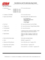
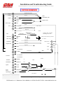
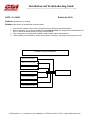
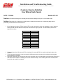
FUNCTIONAL DIAGRAM WIRE
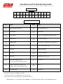
Depth +
Ground
Ground
Depth Finder Signal In
1
2
Ground
DS01
Blue
Depth Finder Cable
3
Black/Purple
Black/Purple
4
Shield
Cluster Lights
5
Blue
Trim
6
Purple/White
Ground
Engine Ground
Speedo
0.0Ω to 542Ω
Dash Light & Compass
7
N/C Serial TX
8
N/C Serial RX
Engine IO
9
Oil Pressure
10
Light Blue
Pink
Water Temp
11
10
Tan
12
11
Grey
13
12
Black
14
13
Shield
Depth Ground
15
14
16
15
240 Ω @ 6 PSI TO 33Ω @ 100 PSI
75 to 857Ω
Engine IO
Shield Ground
1
Power
2
Engine IO
Red
Engine IO
Signal
1
Green
3
2
Temp
No Connection
Temp Speedo
4
White
Tan/Black
4
17
No Connection
18
No Connection
Sea Water
US Range 10Ω F to 280Ω Ε
VDO Range 3Ω to 210Ω
Potentiometer
Attenuator Black/Pink
Resistor
Fuel Sender
Fuel
Tachometer
Ground
Set Button
19
18
Pink/Blue
Mode Button
20
19
Pink/Brown
Speedo
21
20
Purple
22
Purple
Ground
Set
Black
Mode
3A
Switched 12 V
Power Speedo +12
Power
Power
23
22
Red/Purple
Speeds Signal
24
Grey/Pink
5A
15A
+12V
+12Volt Power
1
24
2,3,4,13 and 14 are grounded internally
CDI Electronics • 111 Commerce
Circle • Madison, AL 35758 • Fax 256-772-5701 • www.cdielectronics.com
24