1
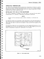
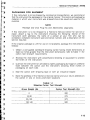
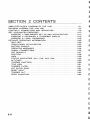
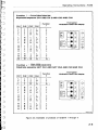
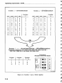
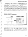
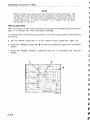
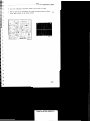
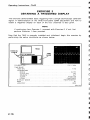
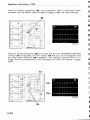
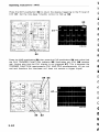
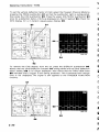
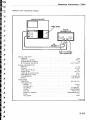
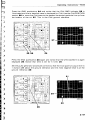
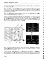
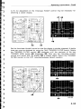
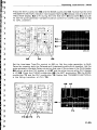
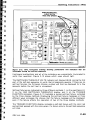
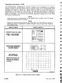
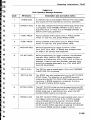
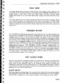
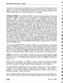
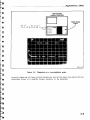
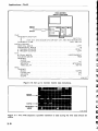
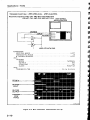
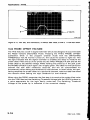
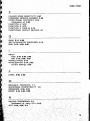
Operating Instructions-7A42
INDICATORS WILL
LIGHT BOTH
iy
i"
is
E3
is
i'
i'
E~
E
i"
i~
'
is
i"
i'
A
4285-290
Figure 2-10. 7A42 front-panel drawing showing pushbuttons and indicators that are
illuminated during the self-test sequence.
front-panel pushbuttons and all of the indicators are momentarily illuminated to
verify their operation. Figure 2-10 shows which ones should light.
4
s
r:
The SWITCHING THESHOLD VOLTS indicator will display 8.8.8.8. during the first
part of the self-test sequence to verify that all segments operate. If there are no
self test failures, the Firmware Version number will then be displayed for a few
seconds before the self test is completed.
Self-test failures are indicated by three different methods: 1. on the mainframe crt,
2. on the 7A42 SWITCHING THRESHOLD display, and 3. on the TRIGGER
FUNCTION indicators. Figure 2-11 illustrates a typical self-test failure, indicated
by the three display methods. Displaying the self-test failure messages in three
different ways increases the chance that the failure message will be displayed,
even if the failure affects the operation of two of the three display methods.
The TRIGGER FUNCTION display indicates a self-test failure with the color red
and self-test passed with the color green. If a failure occurs, the self-test sequence
will stop.
REV JUL 1984
2-49