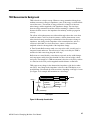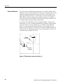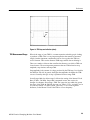
1
Reference
Overview
To take a common mode or differential TDR
measurement (cont.)
Control elements & resources
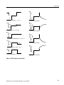
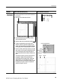
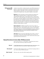
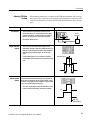
20. When the TDR steps on the two channels are opposite
(one positive and one negative), you can define a math
waveform that represents the difference signal by
pressing the VERTICAL MENU button, selecting the
Vert tab, selecting Waveform M1, On, and then
selecting Define, C1, +, C2, Math Waveform On, and
OK. Set the scale to ρ. (If using volts, subtract the
waveforms.)
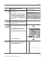
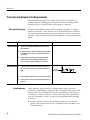
Take a 21. Take your measurement. For more information see Take
measurement
automatic measurements on page 25, or Take cursor
measurements on page 26.
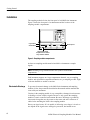
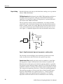
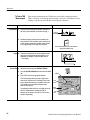
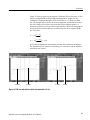
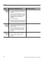
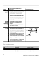
TDT 22. You can make forward and reverse Time Domain
measurements
Transmission (TDT) measurements using the 80E04. To
perform a TDT measurement: connect one sampling
module channel to the input of the device under test and
the other sampling module channel to the output of the
device under test.
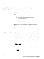
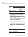
Device under test
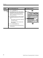
23. Then alternately enable the step generators on one
channel while sampling the transmitted signal on the
other channel to perform forward and reverse TDT
measurements. You measure the step transmitted
through the device, rather than reflections from the
device (as in TDR).
Note: If the second channel is not connected to the same
device as the first channel, crosstalk is displayed, as
opposed to the step transmitted through the device.
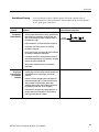
Take a 24. Take your measurement. For more information see Take
measurement
automatic measurements on page 25, or Take cursor
measurements on page 26.
36
80E00 Electrical Sampling Modules User Manual