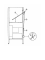
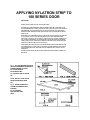
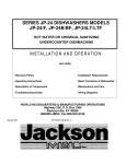
1
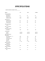
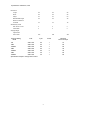
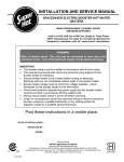
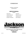
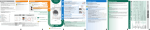
MODEL 100 B/PRB
HIGH TEMPERATURE DOOR
TYPE DISHWASHER
SERVICE MANUAL
INCLUDES:
-Warranty Policy
-Installation Requirements
-Operating Instructions
-Description of Components
-Basic Functions of Dishwasher
-Maintenance and Care
-Illustrated Parts List
-Electrical Diagrams
WORLD HEADQUARTERS & MANUFACTURING OPERATIONS
Highway 25E, P.O. Box 1060
Barbourville, KY 40906
888/800-JMSC
FAX 606/523-9196
March 12,1999 (Reprinted without change)
7610-100-02-00 Rev A
INDEX
SPECIFICIATIONS
2
GENERAL INSTRUCTIONS (Installation/Dimensions)
4
GENERAL INSTRUCTIONS (Operation)
6
GENERAL INSTRUCTIONS (Preventive Maintenance)
7
REMOVAL OF RINSE and/or WASH HEAD ASSEMBLIES
8
TIMER FOR MODEL 100 DISHWASHERS
10
DEFECTIVE TIMER MOTOR
11
FUNCTION of SWITCHES. CIRCUIT BREAKER and
INDICATING LIGHTS
12
REPLACEMENT of SWITCHES in CONTROL PANEL
13
THERMOSTAT ADJUSTMENT
14
SERVICE INSTRUCTIONS
15
RINSE TANK HEATER SYSTEM
16
WASH TANK HEATER SYSTEM
18
REPLACING SEAL and CERAMIC on WASH PUMPS
20
REPLACING SEAL and CERAMIC on RINSE PUMPS
22
INSTRUCTIONS for ADJUSTING TENSION of CANTILEVER
24
APPLYING NYLATRON STRIP TO 100 SERIES DOOR
26
WATER LEVEL CONTROL (For Rinse Tank)
27
WATER LEVEL CONTROL (Initial Fill and Wash-Heat
Circuit)
28
TROUBLE SHOOTING GUIDE
30
PICTORIALS
FRONT VIEW OF MACHINE
37
BACK VIEW OF MACHINE
38
RIGHT SIDE OF MACHINE
39
LEFT SIDE OF MACHINE
40
BOTTOM VIEW OF MACHINE
41
HIGH LEVEL. LOW LEVEL PROBE, VACUUM BREAKER
and INCOMING PLUMBING
42
WASH TANK SUMP W/STRAINERS and ELEMENTS
43
BOOSTER TANK WITH ELEMENT
44
BOOSTER TANK HEATER ELEMENT. WASH TANK
HEATER ELEMENT
45
CONTROL BOX AND CONTROL PANEL COMPONENTS
46
ELECTRICAL DRAWINGS
47
PARTS LIST
52
PARTS DISTRIBUTORS
55
SPECIFICATIONS
SPECIFICATIONS 100 SERIES ITEM #_________
MODEL
100
100B
100PRB
55
55
55
1375
1375
1375
1375
1375
1375
48
10
60
48
10
60
48
10
60
12
12
12
N/A
3
3
188
188
188
140-160
180-195
140-160
180-195
140-160
180-195
180
110
20
12
3/4"
1 - 1/2"
140
110
20
12
3/4"
1 - 1/2"
140
97
20
10.5
3/4"
1 -1/2"
1
1
1
N/A
N/A
1/2
1.5
1.5
1.5
N/A
13
13
Operating Capacity
Racks per hour
(NSF Rated)
Dishes per hour
Glasses per hour
Operating Cycle
Wash Time-Sec
Rinse Time-Sec
Total Cycle-Sec
Wash Tank Capacity
Gallons
Rinse Tank Capacity
Gallons
Wash Pump Capacity
Gal Per Min
Thermometers
Wash- F
Rinse -F
Water Requirements
(NSF Rated)
Inlet Temperature — °F
Gal per hour
Flow Pressure PSI
Flow GPM
Inlet-I.P.S.
Drain - I.P.S.
Wash Pump Motor
Horsepower
Rinse Pump Motor
Horsepower
Electric Heat Wash
KW
Electric Heat Rinse
KW
Specifications 100 Series, cont'd
Dimensions
Length
24"
24"
24"
Width
24"
24"
24"
Height
57"
57"
57"
Standard table height
34"
34"
34"
15"
15"
15"
Dish 19-3/4 x 19-3/4
2
2
2
Combination
2
2
2
400
400
400
Maximum Clearance
for Dishes
Standard Eq. Racks
Shipping Weight
Approximate
basic model
Electrical Rating
Model
100
100B
100PRB
100B
100PRB
100B
100PRB
Volts
Cycle
Phase
Maximum
Total Load Amps
208 or 220
208 or 220
208 or 220
208 or 220
208 or 220
208 or 220
208 or 220
60
60
60
60
60
50
50
1
1
1
3
3
1
1
16
80
80
58
58
80
80
Specifications subject to change without notice.
3
GENERAL INSTRUCTIONS
(INSTALLATION / DIMENSIONS) FOR 100B, PRB SERIES
NOTE: Read the following instructions carefully. Proper installation of your Jackson Dishwasher will assure proper
machine operation.
1. Open side doors, the front door (hook open) and remove dish, cup, and glass racks, and set to one side for
later use. Remove the tape holding the overflow strainer, the pump intake strainer, the wash head assembly
and the rinse head that are inside the machine.
2. Cut straps holding machine to base of crate, ease machine on to floor and slide into place of installation.
3. Connect drain to bottom of machine (1 1/2" IPS female fitting on bottom of wash sump) with proper slope to
conform with local and/or national codes. Drain is a gravity feed system from machine.
4. The incoming water line to the unit must be 3/4" with the capacity to supply 12 gallons per minute with a flow
rate of 20 PSI. The temperature at the unit must be 140° F. • This connection is just before the Y-strainer.
Connect to conform with local and/or national codes (STANDARDS).
5. Electrical connections should be made through hole in bottom of control box to terminal board inside (to the
right lower side of control box). This terminal board is accessible by removing the lower cover plate on control
box. The terminals are marked L1, L2 (requiring 208-230V, single phase), or L1, L2, L3 (requiring 208-230V,
three phase). There is a grounding lug inside of the control box on the bottom left. Be sure all connections
made are tightened properly. Refer to data plate for Voltage and Amperage totals and whether machine is
designed for 50 or 60 cycle operation.
6. Install the proper circuit breaker, wire, and conduit size to conform with local and/or national codes. Refer to
data plate for electrical loads.
7. DO NOT APPLY POWER UNTIL STEP 10.
8. Insert pump intake strainer and overflow strainer, then close door.
9. Turn on hand valve controlling water supply to machine; check for any leaks in plumbing
and connections.
10. To energize electrically, proceed as follows:
a. Turn on customer's circuit breaker controlling machine.
b. Check voltage at incoming terminal L1, L2, and L3 (if applicable). It should match
data plate voltage. Voltage at L1 and L2 should be checked to ground individually to
ensure that a high (or wild) leg is not connected to L1 or L2. (Voltage exceeding 150V
to ground would indicate high leg).
c. If voltages are in required range, turn on 15 amp circuit breaker on side of control box.
The 15 amp circuit breaker protects and controls the motors and control circuit only;
it is not meant to protect or control the rinse heaters.
d. Insert a rack into the machine and close all doors.
e. Turn on the master switch; this supplies voltage to
the operating controls. Then lift up on the rinse/fill
switch. The unit will automatically fill the wash tub with water to a specific level.
f. Open the front door and check the water level. It should be 1/4" below overflow level.
If not, close doors, check the incoming water line making sure that the solenoid valve
fully opens and closes as the switch is turned on and off.
g. If the water is at the proper level, with the front door closed, turn. on the heat switch.
Observe the temperature gauges; the rinse temperature should rise to the specified level
of 180° within five minutes if the incoming water temperature is 140° to the booster
tank.
h. The wash heater will take longer to reach 150°F, as the element is designed for maintaining
temperature, not heating.
i. Turn the manual wash switch on with the door closed. You should hear the water being pumped as it
strikes the top of the machine. Turn off the manual wash switch.
j. The unit is now ready to proceed with the washing of dishes in accordance with the
operating instructions in this manual, and the instruction sticker on the front door of
the dishwasher.
4
GENERAL INSTRUCTIONS
(OPERATION) 100B, PRB
READ INSTRUCTIONS CAREFULLY: Proper operation of your Jackson Dishwasher will assure clean and
sanitized glasses and dishes at optimum efficiency.
DISH PREPARATION
1.
2.
3.
4.
Scrape the dishes thoroughly.
Pre-rinse the dishes by soaking or by spraying off with a pre-rinse hose.
Place the dishes and cups in the dish rack with the cups upside down.
Place the glasses and silverware in the combination glass-silverware rack with the glasses upside down.
Scatter the silverware loosely on the bottom of the rack. Do not put glasses on top of the silverware.
NOTE: When silverware is in an upright position, it washes and rinses better than lying flat. These compartment
silverware racks are available through your dealer or service agency.
MACHINE OPERATION
1. Open the front door and insert the pump intake strainer and overflow strainer.
2. Close all of the doors.
3. Turn the master switch on. Lift the rinse/fill switch up and release. The machine wilt now
automatically fill
the wash tank and energize the wash and rinse heater control circuit.
4. Turn on the heat switch, letting the temperatures rise to the required temperatures on the wash (150°) and
rinse (180-195°) gauges.
5. Raise up the side doors. Slide in a rack of dirty dishes.
6. Add detergent* (see Detergent Recommendation). If an automatic detergent dispenser is used, follow the
manufacturer's instructions.
7. Lower all of the doors.
8. Start the automatic wash and rinse cycle of the dishwasher by flipping the start switch in a full up or down
position. For the next cycle, the switch must go in the opposite direction all of the way. The center position is
off. The light in the top center of the panel will go on when the cycle starts.
9. When the light goes out, open the side doors, slide out the rack of clean dishes, slide in
another rack of dirty dishes, and then repeat steps 6,7. and 8.
10. At the end of a meal period or the end of the day, shut off the heater switch and the master switch. Drain the
machine by removing the overflow strainer. Clean both strainers, the overflow and the inside strainer, of all
foreign debris and build-up and flush out the unit.
*DETERGENT RECOMMENDATION AND RINSE ADDITIVES: We suggest you contact your local detergent
specialists for the correct detergent and rinse additives for the area. To help until one can be reached, we suggest
that you use a non-foaming dishwasher detergent, approximately one-quarter cup in wash tank, when machine is
filled the first time, then one level table-spoon each cycle (or load) thereafter. This may have to be increased or
decreased to obtain satisfactory results.
When manually dispensing powdered detergent in wash tub always distribute over a sufficient area to prevent build
up. Some detergent, when dispensed in a small or concentrated area. may cause deterioration of the stainless tub
or sump.
6
GENERAL INSTRUCTIONS
(PREVENTIVE MAINTENANCE)
(The following is to be performed as needed.)
READ CAREFULLY: Proper maintenance of your Jackson Dishwasher will insure optimum service with a minimum of down
time.
1. To remove all lime and corrosion deposits. (As needed or at least weekly)
a. Fill the machine with wash water as would ordinarily be done for washing.
b. Open door and place one cup or less of de-liming compound into the water. (Be
sure to follow their directions if they vary from these being given) which is available
from your detergent supplier.
c. Turn on the manual wash switch and allow to wash for five minutes.
d. Open door and examine the interior. All lime should be removed and parts should
be shiny. If not, allow to wash for longer period.
e. After the interior is clean, empty the wash water by removing overflow strainer.
f. Replace overflow strainer. Refill machine and allow to run for two minutes, then,
again drain the wash reservoir.
g. Refill as it is ready for regular operation.
2. Clean strainers. (Three times per day)
a. Clean around overflow and pump intake strainer holes.
b. Clean around pump intake (toothbrush makes excellent tool for cleaning).
3.
Clean Y-strainer on incoming water line. (Water to machine must be turned off for this operation)
a. Remove plug and clean strainer.
4. Clean rinse tubes. (Daily)
a. Remove end plugs on lower and upper rinse.
b. Clean all rinse tubes with special brush supplied.
c. If spray holes in the rinse tubes are clogged, they may be cleaned with a pointed tool.
5. Clean wash head assembly. (Daily, or as needed)
a. If spray jets are plugged, use pointed tool to dislodge and flush with water.
b. If lodged items still remain in wash tubes, remove wash assembly by first
removing rinse assembly.
c. Clean assembly at sink by flushing water through spray jets.
d. Reinstall wash and rinse assemblies. (See page with instructions)
6.
Clean any deposits which may have built up on exterior moving parts. (Weekly)
7
(Semi Annually)
REMOVAL of RINSE and/or
WASH HEAD ASSEMBLIES
GENERAL INSTRUCTIONS
1. Turn master switch to off position.
2. Open door and drain machine by lifting overflow strainer.
3. When empty, replace overflow strainer.
4. With wrench, remove pipe fitting holding lower rinse feed pipe to machine and remove feed pipe and rinse head
assembly.
5. Locate Allen head set screw in wash head cap, insert Allen wrench and loosen screw by turning counterclockwise.
6. Turn wash head cap counterclockwise until cap is removed and put cap in safe place.
7. Remove 1 /4" stainless ball bearings carefully and put in a receptacle in a safe place. if any should drop in machine,
you will be able to locate and retrieve if you left the overflow strainer in as suggested in step #3 above.
8. Lift and remove small manifold with short tubes. Put in safe place.
9. Remove 1/4" ball bearing in similar method to step #7.
10. Lift and remove large manifold with long length tubes similar to step #8.
11. The lower fixed race may be left in place.
12. Clean ball bearings by soaking in de-liming solution.
13. Ball bearing race ways may be cleaned by either brushing with de-liming solution (toothbrush makes excellent tool) or
gently clean by rubbing with fine sandpaper or emery cloth.
14. Rinse bail bearings and manifolds thoroughly.
15. To reassemble, first, fill lower race to capacity with 1/4" ball bearings then remove one. This will give proper
movement needed during rotation of assembly.
16. Replace lower manifold and fill race fully with 1/4" ball bearings. Repeat, removing one only.
17. Replace upper manifolds and repeat necessary parts of step #15.
18. Replace wash cap by screwing on center shaft clockwise, finger tight.
19. Back off wash cap about 1/4 turn and tighten Allen set screw.
20. Rotate manifolds in opposite directions; see if they rotate freely. A rule of thumb is to select the longest tube in the
bottom manifold and make sure it moves up and down at least 1/8" and no more than 1/4".
8
21. Replace rinse assembly and feed pipe.
22. Close all doors and refill dishwasher.
23. Run through several cycles and recheck wash arms for easy movement. Adjust if necessary.
24. If removal of upper wash or rinse assembly is necessary, then extra care must be taken to support
assembly. It will drop as one unit, but will be subject to falling apart as wash cap is removed.
ITEM
DESCRIPTION
ITEM
DESCRIPTION
ITEM
1
0126800
P/N
End Plug
7
0137000
P/N
Rinse feed pipe coupling or nut
13
0194500
Spray tube (16)
2
3
4
5
6
0136000
0133000
0132500
0133500
0137000
Rinse arm body
Nylatron washer (2)
Hex nut
Snap ring
Lower rinse feed pipe
8
9
10
11
12
0186500
0187000
0194000
0187500
0200500
Wash cap
Wash cap set screw
Ball bearings (3)
Center shaft
Small manifold
14
15
16
17
18
0201000
0193500
0044700
0188500
Large manifold
Fixed race
Holding nut
Holding bolt
Wash head base
9
P/N
DESCRIPTION
TIMER FOR MODEL 100 DISHWASHERS
General Description
The timer is a self-contained (frame-mounted) timer of the repeating cycle type. It is mounted on
the control panel of Jackson Automatic Dishwashing machines, to control the automatic functions of
these machines. It consists of a clock motor which operates on 60 cycle AC, 220 VAC. In addition to the
clock motor, the timer also contains a driven cam arrangement which operates three micro switches.
Principle of Operation
The timer controls various operations of the automatic washers as per wiring diagram for each
machine, however, the timing cycle and the micro switches are the same for each model. The time for
ONE COMPLETE REVOLUTION of the cam shaft is approximately 120 seconds, allowing two wash
and two rinse operations for each complete revolution of the cam shaft. The micro switch nearest the
timer motor is the hold circuit and uses both the NO and NC contacts. The middle micro switch controls
the wash and uses the NO contact. The micro switch farthest away from the timer motor controls the
rinse and uses just the NC contact.
Service Instructions
CAUTION: ALWAYS REMOVE THE POWER TO THE MACHINE BEFORE WORKING ON THE
CONTROL PANEL OR WHILE SERVICING THE COMPONENTS ON THE SWITCH
PANEL. ALL ELECTRICAL CHECKS SHOULD BE MADE BY QUALI-FIED PERSONNEL.
Timer operation can be observed after removing the control panel from the control box by
loosening the four screws holding it. Hang the control panel using the two right hand screws with the
back side of the panel outward.
If it is determined that the timer is defective, it is recommended that a new timer be installed. However, limited field maintenance can be accomplished as follows:
A frozen contact on a micro switch will be indicated by one function being executed all the time or
the absence of a click when the switch arm is actuated. The micro switch is replaced by:
1. Remove all wires from the timer, properly tag them to assure proper replacement.
2. Remove the two screws which hold the timer to the control panel.
3. One screw holds the micro switches, cams and actuating arms in the frame. This screw
is seen on the side opposite the motor. Remove this screw. NOTE: Be sure to note which
cam goes with which micro switch. Cam nearest timer motor has % raised, cam center,
larger depressed areas, cam farthest from timer motor, smallest depressed areas.
4. The unit can now be taken apart and the defective micro switch replaced.
5. Reassemble. NOTE: The flanges on the cams are such that they only mesh in one
direction. The shorter flange on the cams always points toward the drive motor.
The timers cam drive system is equipped with a clutch to enable one to view the operations of the
cams and micro switches. Remove power to machine BEFORE touching timer. Rotate cams by turning
with fingers; cams will turn in one direction only. Do not force them. As cams actuate switches, listen
for the click of the switch or test the switches with an ohmmeter.
10
DEFECTIVE TIMER MOTOR
A defective motor is indicated by the fact that the cams do not rotate or the machine does not perform the
automatic operations or performs a specific part of the cycle continuously, but works okay on manual. Remember, the
timer motor is controlled by the start switch and the hold micro switch, check this complete circuit before changing
motor. The motor is replaced by:
1.
2.
3.
4.
Remove motor leads from connection points.
Remove the two screws which hold the motor.
Replace with new motor.
Re-connect motor leads to proper points.
NOTE: It may be necessary to remove complete timer to replace motor; if so, follow steps 1 and 2 previous page.
TYPICAL TIMER SWITCH P/N 0177500
A. To upper right terminal start switch
B. To lower right terminal start switch
C.
To right-central terminal manual wash switch.
D. To
upper terminal of rinse switch
E. To
#5 terminal
F. Snorting bar or jumpers connected to all three timer
switches, this terminal
TIMER P/N 0171300, 50 Cycle
P/N 0171500, 60 Cycle
FUNCTION of SWITCHES, CIRCUIT
BREAKER and INDICATING LIGHTS
Circuit breaker
P/N 0012000
Rated 15 amps, controls power to control circuit only, I.E. timer, relays. solenoid valve,
water-level control and motors. Circuit breaker does not cutoff power in control box at
incoming terminal board and rinse heater or its relay contacts. Power is still applied to them
when the circuit breaker is in "off" position.
Master switch
P/N 0157500
This switch interrupts all power going to the control circuit, this means that all switches on
control panel are inoperable until master switch is turned "on."
Start switch
P/N 0162500
This switch controls the timer motor through two circuits (see electrical diagram) it is a threeposition switch, up position = start, middle position = off, down position = start. To start, flip
switch toggle in either up or down position; indicating light in center of panel will light
verifying automatic cycle has started. After cycle ends and you are ready to start a new
cycle, flip toggle to opposite position.
Cycle light
P/N 0083500
This light comes on only when automatic cycle is in progress and extinguishes when cycle is
complete.
Manual wash switch
P/N 0155500
This switch is used to by-pass the timer and operate the wash pump manually. The wash
pump will run as long as this switch is "on." The prime purpose of this switch is to extend the
wash period for extremely soiled dishes before putting them through the normal automatic
cycle. It may also be used as an emergency back-up should the timer ever fail to operate.
The required wash time is indicated on the control panel (front).
Rinse/fill switch
P/N 0154000
This switch is spring-loaded and must be held in its up position to operate. When switch is
operated, water is allowed to fill machine through the rinse heads. It may be used as an
emergency back-up in case of timer failure for rinsing dishes. The required rinse time is
indicated on the front control panel.
Heat switch
P/N 0157500
This switch completes the heat circuit which is composed of automatic control devices that
turn heaters on and off to maintain required temperatures.
Heat light
P/N 0083500
This indicating light remains lit all the time the heat switch is on.
12
REPLACEMENT of SWITCHES in CONTROL
PANEL
There are five switches installed in the control box cover panel. These are the start, master, manual wash,
rinse/fill and heater switches.
Before working on machine, it is important that power be turned off at customer's circuit breaker to prevent the
possibility of electrical shock, trip breaker to "off" position. Then turn machine breaker "on" located right side of
control box.
Remove control panel from control box by removing the four screws holding it in place. Hang the control panel
using the two right hand upper and lower screw recepticles on the control box with backside of panel facing
outward. The five switches are mounted in individual round holes with a keyway. By using a pair of pliers or open
end wrench, it is possible to loosen the inside nut enough to allow the outside nut holding the switch to be removed
by fingers. Push switch out of hole.
If a switch is found to be defective, replacement can be achieved by placing the new switch next to the old one. To
make sure the new switch is not upside down. line up with the keyways. Transfer wires one at a time to the new
switch. If this is not practical, pull wires off, one at a time and tag them for proper replacement.
Put switches back into panel, make sure switch protrudes through panel properly, tighten both nuts, and replace
control panel on control box. Power can now be applied to dishwasher and run through cycles checking all
operations.
1. CONNECTION TERMINALS
2. INSIDE NUT
3. PANEL PLATE
4. OUTSIDE NUT
5. BAT OR TOGGLE HANDLE
13
THERMOSTAT ADJUSTMENT
The thermostat can be adjusted by turning screw # 1 (see picture) on the thermostat control box cover.
(Remember the present setting, in case the problems are elsewhere in the control circuit.) A CW rotation is
used to obtain a lower temperature setting and a CCW rotation is used to obtain a higher temperature
setting. A 1/8 turn of screw # 1 changes the temperature approximately 15° F. If screw # 1 is turned all the
way to its stop in either direction; adjust screw #2 as follows. DO NOT TOUCH THE SCREW SEALED WITH
RED PAINT. When adjusting screw #2 power should be disconnected during adjustment.
Set screw # 1 so that it can be turned equal distances in either direction, then:
- - -if screw # 1 stopped while turning in CW direction, turn screw #2 in CW direction
slowly and only 1/8 of a turn or less per complete cycle of the unit.
- - -if screw # 1 stopped while turning in CCW direction, turn screw #2 in CCW direction
slowly and only 1/8 of a turn or less per complete cycle of the unit.
Three-fourth's of a turn will bring the thermostat to approximately the same setting obtained where
screw # 1 stopped. Check the present temperature setting before attempting any further adjustments. Use
screw # 1 for any further adjustments.
NOTE:
Making large moves in adjusting may cause misalignment
thus increasing the chances that further adjustment cannot be
made and the thermostat will have to be replaced.
NOTE: Some machines were equipped with factory preset
thermostats (wash: P/N 1700-W & rinse: P/N 1700-R) which do not
have adjustment screw #1.
SERVICE INSTRUCTIONS
(INCOMING WATER SOLENOID VALVE)
SOLENOID VALVE
TO TAKE THE VALVE APART
DISASSEMBLY - These valves may be taken apart by unscrewing
the bonnet and the enclosing tube assembly from the valve body
assembly. See Fig. 3. After unscrewing, carefully lift off the bonnet
and enclosing tube assembly. Don't drop the plunger. The "O" ring
seal and diaphragm cartridge can now be lifted out.
Be careful not to damage the machined faces while the valve is
apart.
TO REASSEMBLE - Place the diaphragm cartridge in the body with
the pilot port extension UP. Hold the plunger with the synthetic seat
against the pilot port. Make sure the "O" ring is in place, then lower
the bonnet and enclosing tube assembly over the plunger. Screw
bonnet assembly snugly down on the body assembly.
DIAPHRAGM CARTRIDGE
P/N 0145500
POSSIBLE PROBLEMS
Pilot Port extension #1 clogged
Hole #2 clogged
REMEDY
Pass heated straight pin through hole #2 or
clean hole # 1
15
RINSE TANK HEATER SYSTEM
FUNCTION
The Rinse Tank Heater System is electrically connected in the circuit so that it is dependent upon the
dishwasher being properly filled with and maintaining a safe water level. The automatic fill system, therefore, should
operate properly before the heat system can be engaged. The circuit is controlled by a heat switch (mounted on the
front control panel), a thermostat (mounted behind the lower front panel), a water level control (mounted in the
control box), and a heater relay (mounted in the control box), with the coil being activated by the thermostat.
INDICATORS OF POSSIBLE MALFUNCTION
Once the machine, has been properly filled and the heat system engaged, the heat circuit should operate by
merely turning on the heat switch. Should the rinse tank heat, be it either too high, too low, or no indication of
temperature at all, the following checkouts should be made.
CHECKOUT OF HEATER SYSTEM FOR RINSE TANK (Refer to drawing, figure 1)
NOTE: THE FOLLOWING CHECKOUTS SHOULD BE DONE BY A QUALIFIED SERVICE PERSON OR
ELECTRICIAN.
1. If temperature is too high: adjust thermostat, using thermostat instructions in this manual.
2. If temperature is too low, adjust thermostat as above, then:
a. Turn off power to machine by tripping customer circuit breaker to "off" position.
Turn off machine circuit breaker located on right side of control box.
b. Remove lower cover plate on control box (held by single screw).
c. Make sure rinse temperature is below 180° (preferably about 140°).
d. Reapply power. Turn on master switch and observe heat relay (4 pole mounted lower left inside control
box) while heat switch is turned "on" and "off". If relay contacts move in and out, see instructions under
"B"; if not, proceed with "A".
A. If heat relay does not close:
1. There is an insulated movable bar on the relay across the top of the four contacts. With insulated
probe, depress this bar and observe the rinse thermometer; the temperature should rise noticeably
in a minute or two. If it moves very slowly, it would indicate that one or more elements are faulty. If it
moves constantly higher at a good rate, elements are okay.
NOTE: A check with an amp probe at position E, if available, can be made. Each row of elements should draw 30
amps with a total approximate amperage draw of 60 amps for both rows of elements. (Single phase). Replace any
defective elements.
A. 2. With master and heat switches on:
a. Check position 1, figure 1. Voltage should be 220V; if not, checkout heat
switch and replace if necessary.
b. Check position 2; there should be no voltage.
If there is, readjust thermostat per thermostat adjustment instructions.
c. Check position 3; voltage should be approximately 120V to ground. d. If voltage being
applied
on positions 1, 2. and 3 check out okay. then the relay should be replaced. Coil is probably defective.
16
B. If heat relay closes:
1. Check power supply at incoming terminal board L1 and L2. It should be 220V, approximately.
2. Check power at positions 4 and 5, figure 1. Voltage should read approximately 220V; if not,
check wires for breaks or bad connections.
3. Check power at positions 6 and 7. Voltage should be approximately 220V. If not, check wires for
breaks or bad connections.
4. Temperature should rise as explained in A1 and amperages may be checked according to those
instructions. Replace any defective elements.
FIGURE NO. 1 RINSE HEATER SYSTEM
A. HEATER SWITCH
B. WATER LEVEL CONTROL
C. THERMOSTAT
D. HEATER RELAY
E. RINSE TANK HEATERS
F. AMPROBE TEST POSITION
X. TERMINAL BOARD (9 TERMINALS)
17
WASH TANK HEATER SYSTEM
FUNCTION
The Wash Tank Heater System is electrically connected in the circuit so that it is dependent upon the
dishwasher being properly filled with and maintaining a safe water level. The automatic fill system, therefore, should
operate properly before the heat system can be engaged. The circuit is controlled by a heat switch (mounted on the
front control panel), a water level control (mounted in the control box), a thermostat (mounted behind the lower front
panel), and a heater relay (mounted behind the lower front panel), and a heater relay (mounted in the control box),
with the coil being activated by the thermostat.
INDICATORS OF POSSIBLE MALFUNCTION
Once the machine has been properly filled and the heat system engaged, the heat circuit should operate by
merely turning on the heat switch. Should the wash tank be either too high, too low, or no indication of temperature
at all, the following checkouts should be made.
CHECKOUT OF HEATER SYSTEM FOR WASH TANK (Refer to drawing, fig. 2)
NOTE: THE FOLLOWING CHECKOUTS SHOULD BE DONE BY A QUALIFIED SERVICE PERSON OR
ELECTRICIAN.
1. If temperature is too high: adjust thermostat, using thermostat instructions in this manual.
2. If temperature is too low: adjust thermostat, using thermostat instructions in this manual.
3. If step one or two does not correct the problem, proceed as follows:
a. Turn off power to machine by tripping customer circuit breaker to "off" position.
Turn machine circuit breaker on right side of control box to "off".
b. Remove control panel from control box. Remount panel to right side, using two
screws, with the backside of panel facing you. c. Reapply
power to unit.
d. Wash tank must be emptied, then refilled for each checkout.
e. Wash temperature must be 130 degrees or less. Observe wash heater open switching
relay (two pole; only one pole used), located top relay on left side. With master
switch on, turn heat switch on and off; if relay contacts move in and out. see instructions
under BB. if not. proceed.
AA - - If heat relay doesn't close:
1. There's an insulated bar across the top of two contacts. With insulate probe, depress this bar and
observe wash thermometer; temperature should rise slowly. Watch for approximately five minutes; if
temperature doesn't rise, replace element. If amprobe E is used, the element should draw
approximately 7 amps.
2. With master and heat switches on:
a. Check position 1, figure 2. Voltage should be 220V. If not, check out and replace heat switch.
b. Check position 2; there should be no voltage. If there is, readjust thermostat
per thermostat adjustment instructions.
b. Check position 3; voltage should be approximately 120V to ground.
d. If voltage being applied on positions 1, 2, and 3 checks out okay, then the
relay should be replaced. Coil is probably defective.
18
BB - - If heat relay does close:
1. Check power supply at terminal board #2 between terminals #5 and #7; it should be approximately 220V.
2. Check power at position 4; there should be no voltage.
3. Check position 5; voltage should be approximately 120V to ground.
4. Check power at position 6; voltage should be 220V approximately; if not. check wires for breaks and bad
connections.
5. Temperature should rise as explained in AA1 and amperages may be checked according to those instructions.
Replace any defective elements.
FIGURE NO. 2 WASH HEATER SYSTEM
A. HEATER SWITCH
B. WATER LEVEL CONTROL
C. THERMOSTAT
X. TERMINAL BOARD (9 TERMINALS)
D. HEATER RELAY
E. AMPROBE TEST POSITION
F. WASH TANK HEATER
19
REPLACING SEAL and
CERAMIC on WASH PUMPS
FUNCTION
The pump is part of the total motor-pump system and utilizes one shaft seal and ceramic to prevent
the pump from leaking around the impeller and shaft. One gasket is used to prevent leakage between the
pump mounting plate and the machine pump plate.
REPLACEMENT OF SEAL AND/OR CERAMIC
1. Remove the power source to the machine by turning the circuit breaker to its "off" position on the side
of the control box.
2. Drain the machine by removing the overflow strainer in the wash tank.
3. Support the motor - - remove the four nuts holding the pump/motor to the machine's pump plate.
4. Carefully pull motor outward, move from side to side as required to remove from machine.
5. Set motor and pump on a sturdy stand close to machine or remove wires and conduit to allow
motor/pump to be moved to a better work station.
6. Insert a firm object into the blades of the fan and use a 5/16" ratchet to remove bolt holding impeller.
After the bolt is removed, pull the impeller up and off of the shaft.
7. The ceramic is imbedded in the pump mounting plate and usually does not need replacement, but the
seal normally would when water leaks around the motor shaft area. If replacement of either is
required, proceed as follows:
a. Remove the four bolts holding the pump mounting plate to the motor.
b. Slide the mounting plate up and off of the shaft and motor. The imbedded ceramic and
shaft seal will be removed with the mounting plate.
c. Turn over the plate and push the seal and/or ceramic out of the housing carefully. It
may be necessary to break the ceramic to remove it.
d. Clean the hole where the ceramic was installed.
e. Lightly coat with a lubricant around the new ceramic's edges and "0" ring. Gently press
the ceramic into place against the snap ring in the housing. Make sure that the grooved
side of the ceramic faces the motor and housing snap ring, leaving the smooth side toward
the impeller.
f. Make sure that the woodruff key is in place in the shaft and then set the plate back on the
motor over the shaft.
NOTE: A field tool can be made (to ease installation of seal) from a pipe or tube (3/4" CPVC typical
example) that has proper outside and inside dimensions. It must fit over step down in shaft, but be
close to larger shaft size on outside. To accommodate woodruff, cut long slot in tube. Lubricate tube
slip seal over tube onto shaft.
g. Lightly coat with a lubricant the new seal face and gently press it into place over the shaft
with the seal face against the ceramic. SEE NOTE ABOVE.
h. Place the spring over the shaft with the metal cap up. Press the impeller down onto the
shaft, aligning the keyway of the impeller with the woodruff key.
i. Tighten the impeller washer, lockwasher, and bolt into place. Replace the four bolts
that hold the mounting plate to the motor.
8. Reinstall the pump and motor in the unit by reversing steps one through eight (it is suggested that a
new pump gasket be installed).
IMPELLER ROTATION:
WHEN FACING THE IMPELLER AFTER MOUNTING IT ON THE MOTOR SHAFT, THE
IMPELLER SHOULD TURN IN A CCW DIRECTION.
20
ITEM
P/N
DESCRIPTION
1
0102600
PUMP MOTOR, 50 Cycle
1
0102700
PUMP MOTOR, 60 Cycle
2
0106500
WOODRUFF KEY
3
3691300
WASHER, RUBBER
4
0108000
SNAP RING
5
0105000
CERAMIC FACE w/ "O" RING
6
0104500
PUMP MOUNTING PLATE
7
0105000
SEAL FACE
8
PLATE TO MOTOR MOUNTING
BOLTS & LOCKWASHERS
9
0105000
SEAL ASSEMBLY (SEAL SPRING
& CUP WASHER)
10
0105500
PUMP IMPELLER
11
0107500
IMPELLER WASHER
12
0107000
IMPELLER BOLT & LOCKWASHER
13
0106000
PUMP MOUNTING GASKET
REPLACING SEAL and
CERAMIC on RINSE PUMPS
FUNCTION
The pump is part of the total motor-pump system and utilizes one seal and ceramic to prevent the pump from leaking
around the impeller and shaft. One gasket is used to prevent leakage in between the pump mounting plate and the machine
pump plate.
REPLACEMENT OF SEAL AND/OR CERAMIC
1.
2.
3.
4.
5.
6.
7.
8.
9.
10.
Remove power source to machine by turning circuit breaker to its off position on side of control box.
Drain machine by removing overflow strainer in wash tank.
Support motor - remove the four nuts holding the pump/motor to the machine's pump plate.
Carefully pull motor outward, move from side to side as required to remove from machine.
Set motor and pump on a sturdy stand close to machine or remove wires and conduit to allow motor/pump to be moved to
a better work station.
Remove dust cap over end of motor shaft (opposite impeller end). This can be done by wedging with a screwdriver.
Remove impeller - hold shaft by inserting screw driver in slotted end of shaft and unscrew impeller in counterclockwise
direction.
The ceramic is embedded in the impeller and normally does not need replacement, but it should be checked for cracks or
a worn out surface. If ceramic does need replacement, proceed as follows.
(a) With a pointed, flat tool, work the ceramic and rubber cup out of groove in impeller.
(b) Clean groove of all residue.
(c) Apply small amount of adhesive in groove.
(d) Press new ceramic gently into groove with rubber cup leading the way. (NOTE:
THE CERAMIC HAS ONE SIDE THAT IS GROOVED. THIS SIDE SHOULD BE FACING DOWN INTO THE
RUBBER CUP. THE SMOOTH SURFACE SHOULD BE FACING UP).
The seal is embedded in the pump mounting plate and usually will need replacement when water leaks around motor
shaft area. If replacement is required proceed as follows.
(a) Remove four bolts holding pump mounting plate to motor, must be done with Allen wrench.
(b) Slide mounting plate up off of shaft and motor.
(c) Press seal out of housing carefully.
(d) Clean hole where seal was installed.
(e) Apply a small amount of non-hardening sealant to backside of seal. Insert new seal with a seal driver to prevent
ruffling the edges of seal. Never use screwdriver or similar tool to alternately force edge of seal in place.
Reassemble pump and motor by reversing the above procedure.
22
ITEM
P/N
DESCRIPTION
1
1
0086100
0086000
PUMP MOTOR, 50 Cycle
PUMP MOTOR, 60 Cycle
2
0088000
PUMP MOUNTING PLATE
3
0089000
PUMP CERAMIC FACE w/RETAINER CUP
4
0087500
PUMP IMPELLER SEAL
5
0089500
PUMP IMPELLER
6
0090000
PUMP MOUNTING GASKET
7
0090500
PUMP PLATE TO MOTOR MOUNTING BOLTS
8
0091000
MOUNTING PLATE LOCKWASHERS
9
0091000
PUMP MOUNTING PLATE TO BASE LOCKWASHERS
10
0091500
PUMP MOUNTING PLATE TO BASE NUTS
INSTRUCTIONS for ADJUSTING TENSION
of CANTILEVER
PROBLEM: Doors raise hard, but lower easily.
SOLUTION:
1. Back off (loosen) upper adjusting nuts (F) on both eyebolts (E) about two or three complete turns.
2. Tighten lower adjusting nuts (G) on both eyebolts (E) a complete turn.
3. Check door for easy operation. Adjust further, if necessary.
4. When adjustment is completed, tighten upper adjusting nuts (F) down against angle to lock in position. Check
both eyebolts.
PROBLEM: Doors raise easily, but lower hard.
SOLUTION:
1. Back off lower adjusting nuts (G) carefully, making sure there is still some thread on eyebolt available (both
eyebolts).
2. Check door for easy operation. Adjust further, if necessary.
3. When adjustment is complete, tighten upper adjusting nuts (F) down against angle to lock in position. Check
both eyebolts.
PROBLEM: Doors sticking, or are hard to move up and down.
SOLUTION:
1. Raise doors.
2. Clean inside door channels on machine with a good cleaning compound. It may be necessary to remove
doors to completely clean channel. If so, remove only one door at a time. Make sure cantilever has stop to
prevent pulling other door up and out of channel. If it does not have stop, secure cantilever arm to machine
with doors in the closed position.
3. Build up should be completely removed so it may be necessary to use an abrasive pad (non-metallic) to clean.
4. While you have the door out of channel, make sure it is not dented or crooked. If channel is crooked or
dented, use 1/2" wide block to spread to proper opening.
5. Clean nylatron runners on the doors or replace nylatron, if excessively worn. See instructions on door runners.
6. Check door channels on machine for evenness and burrs.
7. After replacing doors, check for proper operation by raising and lowering with cantilever.
PROBLEM: One side of door higher than other and does not close completely.
SOLUTION:
1. Straighten cantilever arm.
2. This can sometimes be accomplished while arm is on machine by forcing down on the arm connected to the
high door while the other side of the cantilever is pulled up.
3. If step two cannot be accomplished on machine, cantilever will have to be removed and straightened.
24
APPLYING NYLATRON STRIP TO
100 SERIES DOOR
P/N 0051800
INSTRUCTIONS FOR INSTALLING NEW DOOR GUIDES
ITS IMPORTANT WHEN REMOVING THE OLD DOOR GUIDES THAT THE SURFACE BE
CLEANED THOROUGHLY. THIS CAN BE DONE WITH A SOLVENT THAT WILL DISSOLVE
THE REMAINING GLUE AND/OR THE USE OF A FINE SANDPAPER TO SCRATCH THE
SURFACE WHERE THE DOOR GUIDE WOULD MAKE CONTACT WITH THE STAINLESS
STEEL DOOR.
AFTER THIS IS ACCOMPLISHED AND YOU ARE QUITE CONVINCED THAT THE SURFACE
IS CLEANED OF ALL OIL. GLUE. DIRT. DETERGENT ETC.. THEN THE DOOR GUIDE
SHOULD BE PLACED ON A FLAT SURFACE AND A BEAD OF A SILICONE ADHESIVE OR
ANY GOOD NON-HARDENING GLUE SHOULD BE LAID ON THE INSIDE OF THE DOOR
GUIDE'S SURFACE (TOP AND BOTTOM, MAKING SURE THAT NONE OF THE EXPOSED
SURFACE TO THE OUTSIDE HAS ANY GLUE ON IT).
TAKE THE DOOR GUIDE AND SNAP IT OVER THE DOOR'S EDGE AS DESCRIBED IN THE
ATTACHED SKETCH. 00 NOT SLIDE UP THE EDGE. LET THIS DOOR SET FOR AT LEAST
ONE HOUR BEFORE USE SO THAT THE GLUE OR ADHESIVE HAS A CHANCE TO SET
SOMEWHAT.
IF THESE INSTRUCTIONS ARE FOLLOWED. THE DOOR GUIDES SHOULD ADHERE TO
THE DOOR.
Fig. 1 - PUT A STREAM OF SILASTIC
OR NON-HARDENING ADHESIVE IN
INSIDE CORNER OF STRIP.
Fig. 2-SIDE VIEW OF
NYLATRON STRIP.
Fig. 3-SNAP STRIP ON DOOR
LIP.
NOTE: DO NOT SLIDE STRIP
FROM END ALWAYS SNAP
ON.
Fig. 4 - PRESS DOWN WITH
THUMB AND INWARD WITH
FINGERS.
Fig. 5- FINISHED
APPLICATION -END
VIEW.
WATER LEVEL CONTROL(ELS)
(FOR RINSE TANK) P/N 0205000
FUNCTION
The Water Level Control device utilized on power rinse (PRB) models only, automatically maintains
the water level in the rinse tank. The rinse tank water level control is energized by the master switch. The
control is designed to sense when the proper water level is maintained. At this time. the relay in the clear
plastic case will activate, opening the normally closed circuit to the solenoid, which stops the water flow
to the rinse tank.
When water is removed from the tank by the rinse pump, the sensing probe will alert the water level
control by signal to deactivate and return the contact points on relay (in clear plastic case) to the normally
closed position, allowing power to be reapplied to the solenoid valve. Water will again flow into rinse tank
until proper level is reached and maintained.
CHECKOUT
NOTE: ALL ELECTRICAL CHECKS SHOULD BE MADE BY QUALIFIED SERVICE PERSONNEL
OR ELECTRICIAN.
If one of the following problems exist, this control should be checked out as shown below:
1. Water to rinse tank runs continually with the master switch on.
2. Water does not flow into rinse tank when required.
PROCEED WITH CHECKOUTS:
1. Remove power source to machine by moving breaker to "off" position.
2. Remove 4 screws holding control pane! to control box and fasten to control box on right side,
using 2 screws with backside of panel outward.
3. Locate the water level control for the rinse tank circuit (sketch below). Remove, mark. and insulate
for easy replacement wires going to letters C and H on control.
4. Reapply power and turn on master switch.
5. With insulated wired, connect jumper wire between terminals C and H (24 Volt system).
6. If relay (inside clear plastic case marked "X" on drawing below) operates, then the water level
control action can be deemed operational, and other causes should be explored (see
troubleshooting section).
7. If relay doesn't operate, then check relay coil continuity. Replace relay or complete control, as
necessary.
8. Remove power source once again and replace wires removed in (3) to original terminals or new
control, if replacement was made.
27
WATER LEVEL CONTROL (ELS)
(INITIAL FILL AND WASH-HEAT CIRCUIT) P/N 0205000
FUNCTION
This control is activated when the master switch is turned on. The primary function is to automatically
control the proper initial filling of the wash tank, then to activate the wash and rinse tank heat circuit It will
also provide cutoff of the wash and rinse heat circuit, should the water be accidentally drained from the
machine (with the master switch still on). The master switch should be turned off before draining.
This water level control is used in conjunction with two probes (sensors), master switch, fill
switch, rinse relay, thermostat(s). heat relay(s), solenoid or rinse motor.
When the master switch is turned on, the normally closed circuit in the plug-in relay is energized. As the
fill switch is pushed upward and released, the rinse relay contacts close, and the solenoid (or rinse pump on
PRB model) opens and water flows into wash tub. As the water rises in the wash tub, it will cover first the
lower probe (directly above wash element) then reach the upper probe. At this time, the plug-in relay coil will
be activated and open the normally closed contacts, de-energizing the solenoid (or rinse pump).
Simultaneously, the contacts will close on the normally open circuit, energizing the wash-rinse heat circuit.
(Checkout and information concerning that part of the circuit are in the wash heater system or rinse heater
system instruction page of this manual.)
If the water should be drained from the machine while the master switch is still on, the lower probe
will sense the lack of water and de-energize the plug-in relay, which will de-energize the wash-rinse heat
circuit. DO NOT DEPEND ON THIS - - always turn master switch off before draining.
SYMPTOMS OF LEVEL CONTROL FAILURE:
1.
2.
3.
4.
Fill does not take place unless rinse switch is held upward until full.
Initial fill does not stop when it reaches overflow, but continues.
Wash-rinse heat circuit does not activate.
Wash heater remains on (if wash water accidentally emptied with master switch on.)
PROCEED WITH CHECKOUT:
1. Remove power to machine by turning customer circuit breaker to its "off" position. Turn machine
circuit breaker, located on right side on control box. to "off".
2. Remove 4 screws holding control panel on control box. Remove panel and attach to one side of
control box with 2 screws, with back side facing toward you.
3. Locate initial fill and wash-heat circuit water level control board and disconnect wires going to
terminals marked C, H, and L. Mark and insulate wires for replacement.
28
4. Be sure wash tank is empty and master switch and heat switch are off. Carefully reapply power to machine.
Begin by turning master switch on. With an insulated jumper wire, touch jumper between terminals C & H; relay
in clear plastic cube should activate as wire is touched to terminals. Observe relay contacts - - they should pull
in. If they do, remove wire and they should return to original position. Repeat several times to verify action.
Reconnect wires removed.
5. If relay operates, the control can be deemed operational and other causes should be explored. EXAMPLES: 1.
Loose or broken wire to probe or ground (green wire).
2. Dirty probe(s).
3. Solenoid faulty (see instruction page concerning solenoid).
4. Thermostat faulty or needs adjustment (see instruction page concerning thermostat).
5. Wash element faulty (see instruction page concerning wash-heat checkout).
6. If relay does not operate, check voltage being applied to LI - L2 marked on control. It should be 208-230V.
Replace control, if necessary.
7. In any case, always locate sensor (probes) inside wash tub and clean off all deposits (instruct customer; this
should be at least a weekly project).
8. Remove power to machine and replace panel and any wires that were not replaced previously.
TROUBLE SHOOTING GUIDE
PROBLEM
CAUSE
SOLUTION
1- No Voltage to dishwasher,
Nothing on machine
operates.
a. Customer's fuse blown or
a. Replace or reset.
circuit breaker tripped.
2- Machine circuit breaker
2- Turn on or reset.
tripped or turned off.
3- Voltage to machine low or
circuit to machine broken.
3- Contact your electrician
and/or power company for
repair.
Will not fill with electrical
1- Water hand valve off.
1- Turn hand valve on.
2- Master switch not on or
2- Turn on or replace.
power applied even though
other components work.
(B Model)
faulty.
3- Fill switch faulty or loose
wire connection.
4- Solenoid valve does not
operate.
3- Replace switch or wire or
connection terminal.
4- See instruction page
concerning the Solenoid
valve.
5- Water level control faulty
5- See page on water.
6- Y strainer clogged.
6- Turn water to machine
off, remove plug & strainer
screen, clean & replace.
Will not fill with electrical
power applied even though
1- Customer's water hand
1-Tum hand valve on.
valve off.
other components work
(PRB Model)
2- Master switch not on or
2- Turn on or replace.
faulty.
3- Fill switch faulty or loose
wire connection.
4- Rinse motor not operating.
3- Replace switch or wire or
connection terminal.
4- Check connection and
voltage to motor repair or
replace as necessary.
5- Water level control does not
maintain the water level in the
rinse tank.
5- See instruction page
concerning the water level
control for PRB Models.
6- Solenoid Valve does not
operate
6- See instruction page concerning Solenoid Valve.
7- Y-strainer clogged.
7- Turn off water to machine,
remove plug. prepare to
catch hot water & strainer
screen, clean & replace.
30
TROUBLE SHOOTING GUIDE
PROBLEM
Fills slowly and/or rinse is
weak.
Rinse water runs continuously with power on.
CAUSE
1- Low water pressure.
2- Rinse head assemblies limed
up or clogged with other
deposits.
1- Rinse switch sluggish
or faulty.
2- Solenoid valve dirty
or faulty.
3- Water level control
faulty (PRB Models
only).
Rinse water runs with
no electrical power
applied to solenoid
(Master Switch off).
4- Rinse tank probe
coated (PRB Model)
5- Breather tube plugged
or bent closed (PRB
Model only).
1- Water pressure excessive.
2- Solenoid Valve diaphragm
breather hole clogged.
31
SOLUTION
1- Check water pressure by:
a. Turn heat and master
switch off.
b. Empty wash tub.
c. Replace overflow
strainer, close doors.
d. Turn on master switch.
e. As you push up fill
switch, time the seconds it
takes to fill machine to
within 1/4of top of the
overflow tube. It should be
60 seconds. Any more than
5 seconds longer indicates
the water supply &
pressure insufficient.
2- Clean rinse head tubes.
See instruction page
on preventive maintenance.
1- Replace.
2- See special instructions page concerning
Solenoid Valve.
3- See special instructions page concerning
water level control
for PRB Models.
4- Remove & clean probe
then replace.
5- Clean tube or repair.
1- Check using pressure
gauge during flow
period (solenoid
valve open) should
read 20 PSI. if in excess installation of a
Pressure Reducer can
reduce pressure.
2- See instructions
page concerning
Solenoid Valve.
TROUBLE SHOOTING GUIDE
PROBLEM
Machine won't work on automatic. Wash
and rinse work only on manual.
Machine will not automatically fill.
Wash motor does not operate on
automatic or manual but machine rinses
properly.
CAUSE
SOLUTION
1- Timer motor faulty.
1- Pull control panel and observe timer
operation. See instruction page for
changing timer motor.
2- Master or start switch faulty.
2- Replace switch.
3- Start switch in middle position.
3- Position switch up or down fully.
1- Power is off.
1- Check incoming line fuses circuit
breakers.
2- Wire loose or broken to L1 and L2.
2- Check line voltage at L1 and L2 on water
level control and control panel.
3- Master switch faulty.
3- Replace.
4- Water level control faulty.
4- To check water level control, see special
instructions on water level control.
5- High fill probe.
5- Clean or short out probe end to tank, this
will cause the relay on the water level
control to close and return, if this does not
happen, check for loose wire especially a
loose ground wire.
6- Electric solenoid valve not opening.
6- Check electric solenoid valve, see special
information section under solenoid valve
1 - Wash switch faulty.
2- Broken or loose wire from
terminal board to motor.
3- Wash motor faulty.
32
1- Replace.
2- Check for loose or broken
short circuit.
3- Repair or replace.
TROUBLE SHOOTING GUIDE
PROBLEM
Wash motor does not
operate on automatic.
but rinses on automatic
and washes on manual
Machine begins to
wash when master
switch is turned on
without operating
start switch
Machine goes through
entire cycle and
shuts off but washes
through complete cycle
Wash reservoir does
not remain full
Wash motor runs but
machine fails to wash
satisfactorily
CAUSE
SOLUTION
1-Wash micro switch in timer
faulty
1- Check timer, see instruction page on timer
1- Timer motor, micro switch
faulty
1- Check timer, see instruction page on timer
2- Start switch faulty
2- Replace
1- Wash micro switch faulty
1- Check timer, see instruction page on timer
1- Large overflow strainer
not properly seated.
1- Check '0' ring in drain
fitting - Put strainer in
tightly
2- Replace strainer
2- Bottom of strainer (conical
end of tube) bent out of
shape
3- Dirt or mineral deposits in
strainer hole
1- Wash temperature of 150°160° is not maintained
2- Inadequate or improper detergent being used
3- Pump intake strainer is dirty
4- Wash tubes not turning
33
3- See instruction page on
Preventive Maintenance
1- Adjust thermostat on wash
tank, check wash heater
element.
2- Use recommended detergent, see machine's opera
tion instructions
3- See Preventive Maintenance
4- The wash assembly can usually
be freed by bearing down on
the wash assembly and rotating
back and forth. If the as
sembly can't be freed in this
manner, take the wash assembly
apart and the bearing races,
using care not to lose the bear
ings or drop them into the
machine. Clean scale off part
with recommended scale solvent.
See Preventive Maintenance &
instruction for removal of
wash head assemblies.
TROUBLE SHOOTING GUIDE
PROBLEM
Wash Pump leaks
CAUSE
SOLUTION
1- Impeller seal is worn (leaks
around shaft)
1- Remove and inspect pump and motor
assembly, see instruction page on pump
seals and ceramic replacement
2- Pump assembly is not seated to base of
machine (leaks around mounting plate).
2- Replace gasket. Make sure mounting
nuts are tight
1- Valve in water line is not open
2- Rinse tubes are clogged
1- Check to make sure all valves are open
2- See Preventive Maintenance
3- Strainer in water line is full of scale
3- See Preventive Maintenance
4- Rinse and fill switch faulty
4- Check rinse and fill switch
5- Electric solenoid diaphram or plunger not
operating
5- Remove diaphram and plunger, flush
and clean. see instruction page on
Solenoid Valves
6- Coil on the solenoid valve is burned out.
6- See #5 above
7- Insufficient or excessive pressure
7- Check flow pressure which should not
exceed 25 PSI or go below 15 PSI
When master switch is on rinse runs
continually
1- Water level control faulty
1- Check instruction page on water level
controls
Machine goes through entire cycle and shuts
off, but rinses throughout the cycle
1- Defective rinse microswitch
1 - Check timer, instruction page
Rinse and fill switch is on but water does not
come through rinse tubes
Master switch off, rinse runs continually as
soon as power is applied to machine
Extremely high rinse temperature indication
1- Master & rinse switch faulty
2- Loose green ground wire from
water level control
1- Replace rinse and/or master switch 2Tighten ground wire or see instruction
page on solenoids
1 - Thermostat set too high.
1- Adjust thermostat control, see instruction
page on thermostat
2- Thermostat faulty
2- Replace
34
TROUBLE SHOOTING GUIDE
PROBLEM
Low rinse temperature
indication
CAUSE
1- Machine using more water
than normal by rinse running
throughout wash cycle, caused
by faulty rinse microswitch in
timer
2- Incoming water supply not
hot enough
3- Heater switch faulty
4- Setting on thermostat control has been moved from
original factory setting
5- Thermostat faulty
6- Heater faulty
7- Contactor faulty
8- Thermometer faulty
Water leaks from
top of door
1- Spray arms are not moving
freely or ends bent down
ward
Machine wash and
rinse do not operate
1- Timer defective and stopped
in timed cycle
Machine does not
operate at all
1- Circuit breaker tripped
35
SOLUTION
1- If this trouble occurs, it
should be determined that
the rinse is running during
the wash cycle by in
specting the rinse sole
noid and by disconnecting
the wash motor lead at
the terminal board on the
control panel. See instruction page on timer
2- Provide adequate supply of
hot water, see specifications sheet
3- Check heater switch
4- Try new setting. Move the
thermostat control clockwise for higher setting.
5- Check thermostat, see
instruction page
6- Check heater, see instruction
page
7- Check contactor, see instruction page
8- Remove thermometer and
check in hot water against
an accurate thermometer
1 - See instruction page on
preventive maintenance pull upward on ends of
longest wash spray arms ½.
1 - Move start switch to middle
position (start switch is
three position) UP - Start
CENTER-Off, DOWN Start. See instruction
page on timer.
1-Reset circuit breaker on
wall panel. Check voltage
to machine at L1 and L2
at terminal board #TB2
TROUBLE SHOOTING GUIDE
PROBLEM
Rinse pump leaks.
PRB Models only.
CAUSE
1- Impeller seal is worn.
2- Impeller ceramic is worn or
scored.
Indicator light(s) do
not glow at any time.
None of the automatic
functions work (wash, rinse).
1- Lights faulty or poor connection.
1- Start switch faulty.
2- Wire connections poor.
3- Timer rinse or wash microswitch faulty.
Vacuum breaker leaks
1- Limed up.
2- Faulty.
36
SOLUTION
1- See instruction page on
ceramic replacement
2- Same as 1.
1- Replace or correct
connection.
1-Check switch. Replace if
necessary, see instructions
page concerning replace
ment of switches in control
panel.
2- Correct connection.
3- See instruction page
concerning timer &
motor.
1- Disassemble:
a. Remove top using
flat jaw wrench or
channel locks.
b. Remove poppet.
c. Clean poppet & V.B.
top & body.
d. Replace parts removed.
2-Replace needed parts or
whole VB.
FRONT VIEW
ITEM
P/N
DESCRIPTION
ITEM
P/N
DESCRIPTION
1
0068000
BOOSTER TANK
10
0019900
CONTROL BOX & PANEL
2
3
0058000
0151000
WASH TANK HEATER
INSIDE PUMP STRAINER
11
12
0169400
0012000
THERMOSTAT BOX
CONTROL CIRCUIT PROTECTION DEVICE
4
0152000
LARGE OVERFLOW STAINER
13
0101800
WASH PUMP & MOTOR, 50 Cycle
5
6
6A
0047000
FRONT DOOR
DOOR HANDLE
HANDLE JL MODELS
BOTTOM FRONT PANEL (NOT SHOWN)
CANTILEVER ARM CONV. KIT
VACUUM BREAKER
13
14
15
16
16
17
18
0102000
0165500
WASH PUMP & MOTOR, 60 Cycle
7
8
9
0050900
0051000
0055100
6007900
0184301
0169100
WASH & RINSE THERMOMETERS
0085100
0085000
0083300
37
CUSTOMER'S ELECTRICAL CONNECTION
CUSTOMER'S WATER CONNECTION
RINSE PUMP & MOTOR (PRB ONLY) 50 Cycle
RINSE PUMP & MOTOR (PRB ONLY), 60 Cycle
ADJUSTABLE FOOT
RINSE ADDITIVE FITTING
ITEM
P/N
DESCRIPTION
ITEM
P/N
DESCRIPTION
1
1
0085100
0085000
RINSE PUMP & MOTOR (PRB ONLY), 50 Cycle
RINSE PUMP & MOTOR (PRB ONLY), 60 Cycle
11
12
0008700
0011501
CANTILEVER SPRING RODS
CANTILEVER DOOR COUPLER
CUSTOMER'S WATER CONNECTION
13
0007500
BREATHER TUBE (PRB ONLY)
3
0019900
CONTROL BOX & PANEL
14
0009000
CANTILEVER SPRINGS
4
0012000
CONTROL CIRCUIT PROTECTION DEVICE
15
0084500
WATER LEVEL PROBE (PRB ONLY)
2
5
0101800
WATER PUMP & MOTOR, 50 Cycle
16
0068000
BOOSTER TANK
5
0102000
WASH PUMP & MOTOR, 60 Cycle
17
0009400
CANTILEVER EYE BOLTS
DETERGENT DISPENSER FITTING
18
0083300
ADJUSTABLE FOOT
0169100
WASH & RINSE THERMOMETER
19
6007900
CANTILEVER ARM
20
0009100
YOKE ASSEMBLY
0184301
VACUUM BREAKER
21
0049000
SPACER
EXTERNAL VACUUM BREAKER PIPING
22
0010000
SLEEVE
6
9
10
38
RINSE ADDITIVE FITTING
RIGHT SIDE VIEW
ITEM
P/N
1
2
0165500
DESCRIPTION
CUSTOMER'S WATER CONNECTION
CUSTOMER'S ELECTRICAL CONNECTION
ITEM
12
13
3
0019900
CONTROL BOX & PANEL
14
0009000
CANTILEVER SPRING
4
0012000
CONTROL CIRCUIT PROTECTION DEVICE
15
0101800
WASH PUMP & MOTOR, 50 Cycle
5
0084300
HIGH WATER PROBE
15
0102000
WASH PUMP & MOTOR, 60 Cycle
6
0169100
WASH & RINSE THERMOMETERS
16
0007500
BREATHER TUBE (PRB ONLY)
7
0011500
CANTILEVER DOOR COUPLER
17
0084500
WATER LEVEL PROBE (PRB ONLY)
8
6007900
CANTILEVER ARM
18
0085000
RINSE PUMP & MOTOR (PRB ONLY) 60 Cycle
9
0048000
SIDE DOOR
18
0085100
RINSE PUMP & MOTOR (PRB ONLY) 50 Cycle
0083300
ADJUSTABLE FOOT
10
0184300
VACUUM BREAKER
19
11
0008700
CANTILEVER SPRING ROD
20
P/N
DESCRIPTION
DETERGENT DISPENSER FITTING
EXTERNAL VACUUM BREAKER PIPING
RINSE ADDITIVE FITTING
39
ITEM
1
2
3
P/N
0006800
0009000
DESCRIPTION
BOOSTER TANK
DETERGENT SENSOR FITTING
CANTILEVER SPRING
4
5
0008700
EXTERNAL VACUUM BREAKER PIPING
CANTILEVER SPRING ROD
13
14
6
7
8
9
0136000
0200000
0184301
0048000
UPPER RINSE HEAD ASSEMBLY
UPPER WASH HEAD ASSEMBLY
VACUUM BREAKER
SIDE DOOR
15
16
17
18
40
ITEM
10
11
12
P/N
6007900
0011500
0136000
DESCRIPTION
CANTILEVER ARM
CANTILEVER DOOR COUPLER
LOWER RINSE HEAD ASSEMBLY
0200000
LOWER WASH HEAD ASSEMBLY
WASH TANK (NLA)
0083300
0182100
DRAIN OUTLET
ADJUSTABLE FOOT
DETERGENT DISPENSER FITTING
PLUMBING VACUUM BREAKER TO HOOD
BOTTOM VIEW
ITEM
1
2
P/N
0083300
0006800
DESCRIPTION
ADJUSTABLE FOOT
BOOSTER TANK
3
DETERGENT SENSOR FITTING
4
WASH TANK
5
6
0019900
ITEM
7
8
P/N
0012000
0153700
DESCRIPTION
CONTROL CIRCUIT PROTECTION DEVICE
'Y' STRAINER
9
0143000
SOLENOID VALVE
10
0101800
WASH PUMP & MOTOR, 50 Cycle
DRAIN OUTLET
10
0102000
WASH PUMP & MOTOR, 60 Cycle
CONTROL BOX & PANEL
11
0085000
RINSE PUMP & MOTOR (PRB ONLY), 60 Cycle
11
0085100
RINSE PUMP & MOTOR (PRB ONLY), 50 Cycle
41
HIGH LEVEL
PROBE
P/N 0084300
LOW LEVEL
PROBE
P/N 0084500
VACUUM BREAKER P/N 0184301
ITEM
1
1
2
3
4
2
3
4
5
PROBE BOOT
NUTS
LOCKWASHER
PROBE
P/N
0184700
0184700
0184700
DESCRIPTION
BONNET
DISK
GASKET
POPPET
BODY
5 TANK COUPLING
1
2
3
4
5
6
NUT, 6/32 S/S
WASHER RUBBER
PORCELAIN, OUTER
INSERT, SILASTIC
PORCELAIN, INNER
STEM
42
ITEM
1
2
3
P/N
0153700
4
5
6
0055500
0143000
0185000
DESCRIPTION
‘Y’ STRAINER
REMOVABLE FILTER
VALVE FOR HEALTH INSPECTOR
FLOW CONTROL, 3/4"
SOLENOID VALVE 3/4"
PIPE UNION
CUTAWAY VIEW OF WASH SUMP
ITEM P/N
1
2
0005400
DESCRIPTION
DRAIN FITTING
DRAIN '0' RING
3
4
0152000
0058000
OVERFLOW STRAINER
WASH TANK HEATER ELEMENT
5
6
7
015100
INSIDE PUMP STRAINER
WASH TANK THERMOSTAT SHEATH
SUMP WALL
ITEM
P/N
1
DESCRIPTION
DRAIN FITTING WELDED
2
3
0054000
0151000
TO WASH SUMP BOTTOM
DRAIN '0' RING
INSIDE PUMP STRAINER
4
0152000
LARGE OVERFLOW STRAINER
43
ITEM P/N
1
0006800
2
3
4
0058800
HEATER BUS BARS (1 PHASE CONNECTION)
5
0060500
HEATER ELEMENTS (6 EACH)
6
HEATER ELEMENT COUPLING (6 EACH)
BOOSTER TANK
WITH ELEMENTS
(1 PHASE HOOKUP)
END VIEW BOOSTER
TANK
(3 PHASE HOOKUP)
ITEM
1
2
P/N
DESCRIPTION
THERMOSTAT PROBE FITTING
THERMOMETER PROBE FITTING
3
4
0060500
INCOMING WATER FITTING
BOOSTER HEATER ELEMENTS
5
&
0058800
0058900
HEATER ELEMENT BUS BARS
(3 PHASE CONNECTION)
DESCRIPTION
BOOSTER TANK (B MODEL)
(NEW STYLE-NOT SHOWN)
EXTERNAL VACUUM BREAKER FITTING
THERMOSTAT PROBE, FITTING
44
BOOSTER TANK HEATER
ELEMENT P/N 0060500
WASH TANK HEATER ELEMENT
P/N 0058000
45
CONTROL BOX AND CONTROL PANEL COMPONENTS
ITEM
P/N
1
DESCRIPTION
ITEM
P/N
DESCRIPTION
GROUNDING LUG
10
0157500
HEATER SWITCH
2
0165500
CUSTOMER'S ELECTRIC CONNECTION
11
0162500
START SWITCH
3
0123000
HEATER RELAY (3 POLE/3 PHASE)
12
0157500
MASTER SWITCH
0124000
(4 POLE/1 PHASE)
13
0083500
AUTOMATIC INDICATOR LIGHT
4
0121000
RINSE/FILL RELAY
14
0155500
MANUAL WASH SWITCH
5
0121000
WASH MOTOR RELAY
15
0154000
MANUAL RINSE SWITCH
6
0122000
WASH HEATER RELAY
16
0083500
HEATER INDICATOR LIGHT
7
0012000
CONTROL CIRCUIT PROTECTION DEVICE
17
0171300
AUTOMATIC TIMER ASSEMBLY 50 Cycle
8
0205000
RINSE TANK WATER LEVEL CONTROL
17
0171500
AUTOMATIC TIMER ASSEMBLY 60 Cycle
(PRB ONLY)
18
0167000
9
0205000
WASH HEATER WATER LEVEL CONTROL
19
46
TERMINAL BOARD
GROUNDING STUD
R1 & R2: CONTACTORS
M SW: MASTER SWITCH ON-OFF
1-ELS, CONTROL, HIGH LEVEL FILL,
LOW LEVEL CUT-OFF IN WASH
TANK & RINSE TANK, LOW
VOLTAGE SENSOR, 24V. TO
PROBE
H.SW: HEAT & LIGHT SWITCH
THS: INDEPENDENT THERMOSTAT
CONTROL
WASH HEATER: (1)-1500W.
S-SW: START SWITCH • STARTS THE
AUTOMATIC CYCLE WHEN
THROWN TO THE CLOSE SIDE OF
TH: TIMER HOLD • TIMER MOTOR
RUNS ONE HALF CYCLE, THEN
OPENS • TH • TO COMPLETE ONE
MACHINE CYCLE.
TW: TIMER WASH & TR: TIMER RINSE •
CONTROLLED BY CAMS DRIVEN BY
THE TIMER MOTOR
MW SW MANUAL OPERATION WASH
SWITCH • IN THE OFF POSITION
FOR AUTOMATIC OPERATION, ON •
FOR MANUAL OPERATION.
MR-SW: MANUAL RINSE & FILL
SWITCH, SPRING RETURN, LOCKS
IN R2 THROUGH 1-ELS, UNTIL
MACHINE FILLS TO HIGH LEVEL
PROBE IN WASH TANK.
RINSE HEATERS (6) 2200 W HC:
CONTACTOR
CB 1: OVER CURRENT CIRCUIT
BREAKERS-15A.
R1&2: CONTACTOR M SW: MASTER
SWITCH ON OFF
1 ELS, CONTROL, HIGH LEVEL FILL,
LOW LEVEL CUT OFF IN WASH
TANK & RINSE TANK HEAT. LOW
VOLTAGE SENSOR, 24V. TO
PROBE
H SW: HEAT & LIGHT SWITCH
W THS & R-THS: INDEPENDENT
THERMOSTAT CONTROL WASH &
RINSE TANK HEAT WASH
HEATER. (1) 1500 W.
S-SW: START SWITCH - STARTS THE
AUTOMATIC CYCLE WHEN
THROWN TO THE CLOSE SIDE OF
TH: TIMER HOLD, - TIMER MOTOR
RUNS ONE HALF CYCLE, THEN
OPENS - TH TO COMPLETE ONE
MACHINE CYCLE,
TW: TIMER WASH & TR: TIMER RINSE
CONTROLLED BY CAMS DRIVEN
BY THE TIMER MOTOR
MW-SW: MANUAL OPERATION WASH
SWITCH IN THE OFF POSITION
FOR AUTOMATIC OPERATION. ON
FOR MANUAL OPERATION.
MR-SW: MANUAL RINSE & FILL
SWITCH, SPRING RETURN, LOCKS
IN R2 THROUGH 1-ELS, UNTIL
MACHINE FILLS TO HIGH LEVEL
PROBE IN WASH TANK.
48
RINSE HEATERS (6) 2500 W HC:
CONTACTOR (HEATER)
CB.1:
OVER
CURRENT
CIRCUIT
BREAKERS. 15 AMPS RATING
R1, R2 & R3: CONTACTORS (WASH &
RINSE
MOTORS,
AND
WASH
HEATER)
M-SW: MASTER SWITCH ON-OFF
1 ELS, CONTROL, HIGH LEVEL FILL,
LOW LEVEL CUT-OFF IN WASH
TANK & RINSE TANK HEAT, LOW
VOLTAGE SENSOR, 24V. TO
PROBE
H-SW: HEAT & LIGHT SWITCH
W-THS & R-THS: INDEPENDENT
THERMOSTAT CONTROL OF
WASH & RINSE TANK HEAT
WASH HEATER, (1) 1500W.
S-SW: START SWITCH STARTS THE
AUTOMATIC CYCLE WHEN
THROWN TO THE CLOSE SIDE OF .
TH: TIMER HOLD, TIMER MOTOR
RUNS ONE HALF CYCLE, THEN
OPENS TH TO COMPLETE ONE
MACHINE CYCLE.
TW & TR TIMER WASH & TIMER RINSE
CONTROLLED BY CAMS DRIVEN BY
THE TIMER MOTOR
MW SW MANUAL OPERATION WASH
SWITCH IN THE OFF POSITION FOR
AUTOMATIC OPERATION, ON FOR
MANUAL OPERATION.
MR-SW: MANUAL RINSE & PILL
SWITCH, SPRING RETURN, LOCKS
IN R2 THROUGH 1.ELS. UNTIL
MACHINE FILLS TO HIGH LEVEL
PROBE IN WASH TUB.
49
RH RINSE HEATERS ((6) 2500 W
HC: CONTACTOR (HEATE R) CB 1
OVER CURRENT, CIRCUIT
BREAKER 15AMP RATING
Rl & R2 CONTACTORS (WASH &
RINSE MOTOR)
M SW MASTER SWITCH ON OFF
1 ELS. CONTROL. HIGH LEVEL FILL,
LOW LEVEL CUT-OFF IN WASH
TANK & RINSE TANK HEAT, LOW
VOLTAGE SENSOR, 24 V. TO
PROBE
H SW: HEAT & LIGHT SWITCH
W THS & R THS INDEPENDENT
THERMOSTAT CONTROL WASH &
RINSE TANK HEAT. WASH
HEATER. (1)1500 W.
R3. CONTACTOR (WASH HEATER)
S.SW: START SWITCH, STARTS THE
AUTOMATIC CYCLE WHEN
THROWN TO THE CLOSE SIDE OF
TH
TH: TIMER HOLD: TIMER MOTOR
RUNS ONE HALF CYCLE, THEN
OPENS TH TO COMPLETE ONE
MACHINE CYCLE
TW & TR: TIMER WASH & TIMER
RINSE: CONTROLLED BY CAMS
DRIVEN BY THE TIMER MOTOR
MW-SW: MANUAL OPERATION WASH
SWITCH: IN THE OFF POSITION
FOR AUTOMATIC OPERATION ON
FOR MANUAL OPERATION. ON
LOCKS OUT RINSE MOTOR
MR SW: MANUAL RINSE & FILL
SWITCH. SPRING RETURN,
LOCKS IN R-2 THROUGH 1 ELS,
UNTIL MACHINE FILLS TO HIGH
LEVEL PROBE IN WASH TUB
2 ELS: CONTROLS THE WATER LEVEL
IN THE RINSE TANK THROUGH
LOW VOLTAGE SENSOR. 24 V. TO
PROBE FOR OPENING THE
SOLENOID VALVE
50
HC: CONTACTOR (HEATER) RH: RINSE
HEATERS. (6) 2500 W.
CB-1: OVER CURRENT, CURRENT
CIRCUIT BREAKER,
15AMPS RATING R1 & R2:
CONTACTORS (WASH &
RINSE MOTORS)
M-SW: MASTER SWITCH ON-OFF
1 ELS: CONTROL, HIGH LEVEL FILL,
LOW LEVEL CUT-OFF IN WASH
TANK & RINSE TANK HEAT, LOW
VOLTAGE SENSOR, 24 V. TO
PROBE
H-SW: HEAT & LIGHT SWITCH R-3:
CONTACTOR (WASH HEATER) W-THS &
R-THS: INDEPENDENT THERMOSTAT
CONTROL WASH & RINSE TANK HEAT;
WASH HEAT WH: WASH
HEATER (1)1500 W.
S-SW: START SWITCH, STARTS THE
AUTOMATIC CYCLE WHEN
THROWN TO THE CLOSE SIDE OF
TH
TH: TIMER HOLD: TIMER MOTOR RUNS
ONE HALF CYCLE, THEN OPENS
TH TO COMPLETE ONE MACHINE
CYCLE
TW & TR: TIMER WASH & TIMER RINSE
CONTROLLED BY CAMS DRIVEN
BY THE TIMER MOTOR.
MW-SW: MANUAL OPERATION WASH
SWITCH: IN THE OFF POSITION
FOR AUTOMATIC OPERATION: ONFOR-MANUAL OPERATION, ON
LOCKS OUT RINSE MOTOR
MR-SW: MANUAL RINSE & PILL
SWITCH, SPRING RETURN, LOCKS
IN R-2 THROUGH 1-ELS, UNTIL
MACHINE FILLS TO HIGH LEVEL
PROBE IN WASH TUB.
2-ELS: CONTROLS THE WATER LEVEL
IN THE RINSE TANK THROUGH
LOW VOLTAGE SENSOR, 24 V. TO
PROBE FOR OPENING THE
SOLENOID VALVE
51
PARTS LIST FOR MODEL 100
B/PRB DISHWASHERS
PART
NUMBER
DESCRIPTION
SERIAL
NUMBERS
100
0006800
0006900
Booster Tank for machine (stripped) B
Booster Tank for machine (stripped) PR
All
All
1
1
0006900
Booster Tank for machine (stripped) PRB
All
1
6007900
Cantilever Assy Comp. (includes pans 79; 83; 87; 90; 94; 96
100; 103; 106; 109; 112) N/S (Conversion Kit)
All
1
0008901
Cantilever Ann, ONLY N/S (1" Dia.) Old Style was 3/4"
All
1
0008501
Cantilever Arm Plugs
0008400
Cantilever Ball Handle Grips
All
1
0008700
Cantilever Spring Rods
All
1
0009000
Cantilever Springs
All
2
0009100
Cantilever Yoke Assembly
AF11140
2
0009400
Cantilever Eye Bolts
All
2
0009600
Cantilever nuts, for eye bolts
All
4
0010000
Cantilever sleeve
All
2
0010300
Cantilever bolt, for sleeve 1/4" x 1 3/8"
All
2
0010600
Cantilever washer flat, for sleeve bolt 1/4"
All
4
0010900
Cantilever acorn nut, for sleeve bolt 1/4"
All
2
0011200
Cantilever lockwasher, for sleeve bolt 1/4"
All
2
0011500
Cantilever coupler door, to cantilever
All
2
0012000
Circuit Breaker, 15 amp (specify number from Part)
Specify
1
0019600
Control Box comp. wired
AF2100
1
0019900
Control Box comp. wired B
AF2100
1
0020200
Control Box comp. wired PR
AF2100
1
0020500
Control Box comp. wired PRB
AF2100
1
0021600
Control Box (stripped) ONLY
AF1149
1
0026500
Control Box front panel wired
AF1149
1
0026800
Control Box front panel wired B
AF1149
1
0027100
Control Box front panel wired PR
AF1149
1
0027300
Control Box front panel wired PRB
AF1149
1
0028400
Control Box front panel BLANK
All
1
0029000
Control Box, lower front cover (ONLY)
AF1149
1
0029900
Control Box, special adaptor cover (for field installation)
All
1
0047000
Door, front, standard model
All
1
0047500
Door, front, corner model
All
1
0048000
Door, side
All
2
0048500
Door catch, front
All
1
0049000
Door spacer, side
All
2
0049500
Door screw, for spacer 1/4" x 1 3/8"
All
2
0010600
Door washer flat, 1/4", s/s
All
2
0010900
Door acorn nut, for spacer 1/4", s/s
All
2
0050900
Door knob (front w/screw)
All
1
0051800
Door strips or guides
All
6
0053100
Door ONLY (false panel for corner model)
All
1
0054000
Drain '0' ring
1800; All
1
0055500
Flow Control, 11.5 GPM, 3/4"
AF11943
1
0056000
Gauge, pressure, 0-60, bottom connection
All
1
0058000
Heater element. Immersion, flange type, w/gasket, 220V, 1500W
All
1
0058500
Heater gasket. Immersion element flange type, above
All
1w
0058800
Heater bus bars, 3 hole
All
2
0058900
Heater bus bars, 2 hole
All
2
0060500
Heater element, Immersion, screw plug type, 220V, 2500W
All
6
0083500
Light indicator
All
2
52
PART
NUMBER
DESCRIPTION
0084300
0084500
Probe; small Lundy
Probe, large Warrick Hi-level
0084700
Probe; cover rubber (for 845)
0085000
Pump assy. comp. w/motor, 1/2 HP, 3450 RPM, Rinse (PRB Only)
0085100
Pump Assembly, complete w/motor, 1/2 HP, 2850 RPM, Jet,
Rinse (PRB Only), 50 Cycle
0086000
0086100
Pump, motor 115/230V 1/2 HP, 3450 RPM, Jet, Rinse (PRB Only)
SERIAL NUMBERS
100
2800
All
2w
1R
All
1R
1200
1R
(All 50 Cycle)
1
1200
1R
Pump, Motor 115/230V, 1/2 HP, 2850 RPM, Jet, Rinse (PRB Only)
50 Cycle
(All 50 Cycle)
1
All
1R
1200
1R
All
1R
1200
1R
Pump gasket (for pump parts 850-863) (mounting)
All
1R
0090500
Pump bolts (for pump parts 850-863)
All
4R
0091000
Pump lockwashers (for pump Parts 850-863-920-925)
All
4x
0091500
Pump nuts (for pump parts 863-862-920-925)
All
4x
0101800
Pump Assembly, complete, Jet 1 HP, 1450RPM 50 Cycle
0102000
Pump Assembly, complete, Jet 1 HP 1725 RPM
0102600
Pump Motor, Jet, 115/208-230V, 1 HP 1450RPM 50 Cycle
(All 50 Cycle)
1
0102700
Pump Motor, Jet, 100/208V-230V, 1 HP 1725 RPM
All
1w
0104500
Pump mounting plate (for part 1020)
All
1W
0105000
Pump seal and ceramic (for part 1020)
All
1w
0105500
Pump impeller (for part 1020)
All
1w
0106000
Pump gasket, square (for part 1020) (mounting)
All
1w
0106500
Pump, Woodruff Key (for part 1020)
All
1w
0107000
Pump bolt, Impeller, s/s 5/16"-18x1" (for part 1020)
All
1w
0107500
Pump washer, Impeller (for part 1020)
All
1w
0108000
Pump snap ring (for part 1020)
All
1w
0090500
Pump bolts, 3/8"-16x 11/4" Cap HH (for part 1020)
All
4W
0091000
Pump lockwashers (for part 1020)
All
8w
0117500
Rack, SQUARE, 19 3/4" x 19 3/4" (cup, bowl & glass) moulded
for model JL-100
0117800
Rack, SQUARE, 19 3/4" x 19 3/4" (dish) moulded
for model JL-100
0120000
Regulator repair KIT, PRESSURE, 3/4" Watts
0121000
Relay, 220V, 2-pole, HW (used on rinse & wash circuit)
0122000
Relay, 220V 2-pole, Wash Heater
0123000
0124000
0087500
Pump seal (for pump parts 850-863-920-925)
0088000
Pump mounting plate (for pump parts 850-863)
0089000
Pump ceramic face w/retainer cup (for pump parts 850-863-920-925)
0089500
Pump impeller 2 3/4 " dia. 7/16" tap (for pump parts 850-863)
0090000
(All 50 Cycle)
1
All
1W
All
1
1149
1
Relay, 220V, 3-pole, HW (used on heat circuit, three phase)
All
1
Relay, 220V, 4-pole, HW (used on heat circuit, single phase)
All
1
0127000
Rinse Head, End plug (nylon)
All
4
0132500
Rinse head hex bushing, s/s
All
2
0133000
Rinse head nylatron washer
All
2
0133500
Rinse head snap rings, s/s
All
2
0134000
Brush, tube cleaning, large
All
1
0136000
Rinse head upper & lower interchange
All
2
0136500
Rinse head feed pipe, Upper
All
1
0137000
Rinse head feed pipe, Lower
All
1
0143000
Solenoid valve, 3/4", 220V, JE (use 0143100)
All
0143100
Solenoid valve, 3/4", 220V, JE, GP
0144000
Solenoid valve coil, 220V, JE (for 1/2" &3/4")
0145500
Solenoid valve diaphragm cartridge, and '0' ring, 3/4", JE
0145600
Solenoid valve diaphragm cartridge, 3/4" JE, GP
0148000
Solenoid valve “O” ring, 3/4", JE
0148500
Solenoid valve, plunger assembly, for 1/2" and 3/4", JE
0148600
Solenoid valve plunger assembly, 1/2" & 3/4", JE, GP
0150000
Solenoid valve strainer screen, 3/4" JE
0150100
Solenoid valve gasket, 3/4" JE, GP
0151000
0152000
1
1
2076
All
1
1
1
All
1
2076
1
All
1
Strainer, small pump intake
All
1
Strainer, large overflow
All
1
1
1
53
PART
NUMBER
SERIAL NUMBERS
100
Strainer, 'Y', 3/4"
Switch, rinse/fill (All) (SPDT) momentary slip disconnect
All
AF24, 451; 2618; 1149
1
1
0155500
Switch, manual wash (DPDT) (All) Slip disconnect
AF24, 451; 2618; 1149
1
0157500
Switch, master (DPST) (All) Slip disconnect (used on
3700
4000
DESCRIPTION
AF24, 451; 2618; 1149; 1059
1
0157500
wash, heat & conveyor on 39's)
Switch, heat (DPST) (All) Slip disconnect
1149
1
0162500
Switch, start (SPDT) (All) Slip disconnect
1149
1
0165500
Terminal Board, 3 pole, complete
All
1
0166000
Terminal Board, 2 pole, 70 amp, with/mount channel
All
1
0167000
Terminal Board, 9 pole, complete slip terminal
1149
1
0169100
Thermometer, wash or rinse, standard
All
1
0170000
Thermostat, standard (use 0170018 or 0170023)
All
0170018
Thermostat, rinse, 180° fixed
0170023
Thermostat, wash, 150° fixed
0171300
Timer, 220V w/wires and mounting plate, 50 Cycle
0171500
Timer, 220V w/wires and mounting plate
0172700
Timer Motor, 220V (for module type timer), 50 Cycle
0173000
1
1
1
(All 50 Cycle)
1
All
1
(All 50 Cycle)
1
Timer motor, 220V (for module type timer)
All
1
0177500
Timer micro switches, plastic module type (for Eagle Bliss)
All
3
0180000
Track, standard, front or back (use 0180000)
All
1
0180000
Track, comer model, complete (convertible)
All
1
0182000
Vacuum breaker, poppet for 1/2" & 3/4" Febco (obsolete)
BF5490
1
0182500
Vacuum breaker, gasket for 1/2" & 3/4" Febco (obsolete)
BF5490
1
0183500
Vacuum Breaker, 3/4", Watts (use 0184301) (Conbraco)
AF13,034
1
0183501
Vacuum Breaker Repair Kit, 3/4", Watts (use 0184301
)(Conbraco)
Vacuum Breaker, 3/4" Sloan (use 0184301) (Conbraco)
AF13,034
1
0184300
WOO
Vacuum Breaker Kit (float & seal) 3/4'' Sloan
0185000
Valve, 1/4" (for Health Inspector's gauge)
All
1
0186500
Wash head cap w/race
AF19,035
2
0187000
Wash head cap set screw
AF19,035
2
0187500
Wash head center shaft
AF19,035
2
0188500
Wash head holding bolt
AF19,035
2
0044700
Wash head nut for holding bolt (nylon insert)
AF19,035
2
0193500
Wash head fixed race
AF10,282
2
0194000
Wash head bearings, 1/4", s/s
All
114
0194500
Wash head spray tube ONLY, long length
All
(as required)
0200000
WASH HEAD ASSY., UPPER & LOWER INTERCHANGE
All
2
0200500
Wash head, small manifold w/tubes
All
2
0201000
Wash head, large manifold w/tubes
All
2
0205000
Water level control, Curtis, 220V
AF23,344; 2526; All; All
1
0205500
Water level control, relay ONLY, Curtis
AR23,344; 2526; All; All
1
0206000
Water level control, printed board ONLY, Curtis
AF23,344; 2526; Ail; All
1
0009459
Rack support rod (Vee Shape) Rod only
0008201
Cantilever arm support bracket
0055001
Bottom front panel
0136700
Vertical feed pipe (inside tank) upper to lower rinse arm
0163700
Front door switch (some models) 3 terminal
0163800
Side door switch (some models) 6 terminal
0049801
Spacer Kit tor door wraparound
0138900
Rinse feed pipe support
6047603
Conversion kit straight-thru to corner
049800
Door wraparound
80001
Track rod support assembly
0058200
Heater element, flange tpe 208V, 1500W
0051900
Door plugs black plastic
6047100
Conversion kit corner to straight-thru
54