1
HP LaserJet 5200/5200L Series printers
Service Manual
Download Service Manual and Resetter Printer at http://printer1.blogspot.com
Download Service Manual and Resetter Printer at http://printer1.blogspot.com
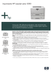
HP LaserJet 5200 Series printers
Service Manual
Download Service Manual and Resetter Printer at http://printer1.blogspot.com
Copyright and license
Trademark credits
© 2006 Copyright Hewlett-Packard
Development Company, L.P.
Microsoft®, Windows®, and Windows NT®
are U.S. registered trademarks of Microsoft
Corporation.
Reproduction, adaptation, or translation
without prior written permission is prohibited,
except as allowed under the copyright laws.
Linux is a U.S. registered trademark of Linus
Torvalds.
The information contained herein is subject
to change without notice.
PostScript® is a trademarks of Adobe
Systems Incorporated.
The only warranties for HP products and
services are set forth in the express warranty
statements accompanying such products
and services. Nothing herein should be
construed as constituting an additional
warranty. HP shall not be liable for technical
or editorial errors or omissions contained
herein.
UNIX® is a registered trademark of The
Open Group.
Energy Star® and the Energy Star® logo are
U.S. registered marks of the United States
Environmental Protection Agency.
Edition 1, 3/2006
Part number Q7543-90934
Download Service Manual and Resetter Printer at http://printer1.blogspot.com
Table of contents
1 Product information
Quick access to printer information ...................................................................................................... 2
Printers at a glance .............................................................................................................................. 3
HP LaserJet 5200 Series printers ........................................................................................ 3
Features at a glance ............................................................................................................................. 4
Walkaround .......................................................................................................................................... 6
Control-panel overview ......................................................................................................................... 8
Printer software .................................................................................................................................. 10
Printer drivers .................................................................................................................... 10
Driver Autoconfiguration .................................................................................... 10
Update Now ...................................................................................................... 11
HP Driver Preconfiguration ............................................................................... 11
Additional drivers ............................................................................................................... 11
Opening the printer drivers ................................................................................................ 12
Software for Macintosh computers .................................................................................... 12
Installing Macintosh printing system software for networks .............................. 13
Installing Macintosh printing system software for direct connections
(USB) ................................................................................................................ 13
To remove software from Macintosh operating systems ................................... 14
Software for networks ........................................................................................................ 14
HP Web Jetadmin ............................................................................................. 14
UNIX .................................................................................................................. 14
Linux .................................................................................................................. 15
Utilities ............................................................................................................................... 15
HP Easy Printer Care Software ......................................................................... 15
Embedded Web server ..................................................................................... 15
Other components and utilities .......................................................................... 15
Selecting print media .......................................................................................................................... 16
Supported media sizes ...................................................................................................... 16
Supported media types ...................................................................................................... 18
2 Installation and configuration
What is in the box ............................................................................................................................... 20
Identification ....................................................................................................................................... 21
Model and serial numbers ................................................................................................. 21
Site requirements ............................................................................................................................... 22
Physical specifications ....................................................................................................... 22
Space requirements ........................................................................................................... 22
Input/Output (I/O) configuration .......................................................................................................... 23
ENWW
iii
Download Service Manual and Resetter Printer at http://printer1.blogspot.com
Parallel configuration ......................................................................................................... 23
USB configuration .............................................................................................................. 23
Connecting the USB cable ................................................................................ 23
Network configuration ........................................................................................................ 24
Manually configuring TCP/IP parameters from the control panel ...................... 24
Setting an IP address ....................................................................... 24
Setting the subnet mask ................................................................... 25
Setting the default gateway .............................................................. 25
Disabling network protocols (optional) .............................................................. 26
To enable or disable IPX/SPX .......................................................... 26
To enable or disable AppleTalk ........................................................ 26
To disable DLC/LLC ......................................................................... 27
Enhanced I/O (EIO) configuration ..................................................................... 27
HP Jetdirect EIO print servers .......................................................... 27
Connecting to a network or a computer ............................................................................. 27
Installing printer memory .................................................................................................................... 30
To install printer memory ................................................................................................... 30
Checking DIMM installation ............................................................................................... 34
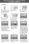
Installing CompactFlash cards ........................................................................................................... 35
Checking CompactFlash installation .................................................................................................. 39
Enabling memory (Windows only) ...................................................................................................... 40
3 Maintenance
Managing supplies ............................................................................................................................. 42
Approximate print-cartridge replacement intervals ............................................................ 42
Managing the print cartridge .............................................................................................. 42
Print-cartridge life expectancy ........................................................................... 42
Print-cartridge storage ....................................................................................... 42
HP print cartridges ............................................................................................ 42
HP policy on non-HP print cartridges ................................................................ 42
Print-cartridge authentication ............................................................................ 43
HP fraud hotline and Web site .......................................................................... 43
Checking supply levels ...................................................................................................... 43
To check supplies by using the control panel ................................................... 43
To check supplies by using HP Web Jetadmin ................................................. 43
To check supplies using the embedded Web server ........................................ 43
Replacing supplies and parts ............................................................................................................. 44
Supply replacement guidelines .......................................................................................... 44
Life expectancy of consumable parts ................................................................................ 44
Changing the print cartridge .............................................................................................. 44
To change the print cartridge ............................................................................ 45
Cleaning the printer ............................................................................................................................ 48
Cleaning the printer manually ............................................................................................ 49
Cleaning the paper path using the printer control panel .................................................... 49
Cleaning spilled toner ........................................................................................................ 50
Vacuum specifications ...................................................................................... 50
4 Theory of operation
Engine control system ........................................................................................................................ 52
Power-on sequence ........................................................................................................... 53
iv
ENWW
Download Service Manual and Resetter Printer at http://printer1.blogspot.com
Motors, fans, and solenoids ............................................................................................... 53
Laser/scanner system ........................................................................................................................ 55
Pickup-and-feed-system ..................................................................................................................... 56
Cassette (tray 2) pickup mechanism ................................................................................. 57
Multipurpose-tray (tray 1) pickup mechanism .................................................................... 58
Jam detection .................................................................................................................... 58
Image-formation system ..................................................................................................................... 59
Image-formation process ................................................................................................... 60
Latent-image formation block ............................................................................................ 60
Step 1: primary charging ................................................................................... 60
Step 2: laser-beam exposure ............................................................................ 61
Development block ............................................................................................................ 61
Step 3: developing ............................................................................................ 61
Transfer block .................................................................................................................... 61
Step 4: image transfer ....................................................................................... 61
Step 5: separation from the drum ...................................................................... 62
Fixing block ........................................................................................................................ 62
Step 6: fusing .................................................................................................... 62
Drum-cleaning block .......................................................................................................... 62
Step 7: drum cleaning ....................................................................................... 62
Print cartridge .................................................................................................................... 63
Print-cartridge activation .................................................................................................... 63
5 Removal and replacement
Removal and replacement strategy .................................................................................................... 66
Introduction ........................................................................................................................ 66
Required tools .................................................................................................................... 66
Types of screws ................................................................................................................. 67
Service approach ............................................................................................................... 67
Before performing service .................................................................................................. 68
After performing service ..................................................................................................... 68
Parts removal order ........................................................................................................... 68
Customer self-repair parts .................................................................................................................. 70
Tray 1 pickup roller ............................................................................................................ 70
Tray 2 pickup roller ............................................................................................................ 72
Tray 2 separation pad ........................................................................................................ 73
Tray 3 retard roller ............................................................................................................. 74
Tray 3 pickup and feed rollers ........................................................................................... 75
Formatter ........................................................................................................................... 76
CompactFlash cards .......................................................................................................... 77
DIMMs ............................................................................................................................... 80
Control-panel overlay ......................................................................................................... 84
Duplexer ............................................................................................................................ 84
External doors, covers, and panels .................................................................................................... 86
Right cover ......................................................................................................................... 86
Lower back cover ............................................................................................................... 86
Face-up bin ........................................................................................................................ 87
Top cover ........................................................................................................................... 89
Left cover ........................................................................................................................... 92
Left front cover ................................................................................................................... 94
ENWW
v
Download Service Manual and Resetter Printer at http://printer1.blogspot.com
Face-down cover ............................................................................................................... 95
Tray 2 ................................................................................................................................. 96
Right front cover ................................................................................................................ 96
Right lower cover ............................................................................................................... 97
DC controller cover .......................................................................................................... 100
Cartridge door unit ........................................................................................................... 100
Control panel ................................................................................................................... 108
Internal assemblies .......................................................................................................................... 110
Laser/scanner .................................................................................................................. 110
Formatter ......................................................................................................................... 111
Fuser ................................................................................................................................ 112
Cassette-paper pickup unit .............................................................................................. 113
Face-down delivery unit ................................................................................................... 118
Main motor ....................................................................................................................... 120
Fuser motor ..................................................................................................................... 125
Main fan ........................................................................................................................... 126
Sub fan ............................................................................................................................ 129
Registration unit ............................................................................................................... 134
Transfer roller .................................................................................................................. 135
Paper-feed unit ................................................................................................................ 136
Printed circuit assemblies (PCAs) .................................................................................................... 139
DC controller .................................................................................................................... 139
High-voltage power supply .............................................................................................. 142
Low-voltage power supply PCA ....................................................................................... 151
Duplexer ........................................................................................................................................... 155
Duplexer .......................................................................................................................... 155
Duplexer left cover ........................................................................................................... 156
Duplexer right cover ......................................................................................................... 157
Duplexer top cover ........................................................................................................... 158
Duplexer back cover ........................................................................................................ 159
Duplexer feed motor ........................................................................................................ 161
Duplexer fan .................................................................................................................... 164
Duplexer PCA .................................................................................................................. 167
500-sheet feeder .............................................................................................................................. 169
500-sheet feeder front cover ............................................................................................ 169
500-sheet feeder left front cover ...................................................................................... 170
500-sheet feeder left cover .............................................................................................. 170
500-sheet feeder right front cover .................................................................................... 172
500-sheet feeder right cover ............................................................................................ 173
500-sheet feeder rear dust cover ..................................................................................... 175
500-sheet feeder paper-pickup unit ................................................................................. 176
500-sheet feeder lifter drive unit ...................................................................................... 180
500-sheet feeder drive unit .............................................................................................. 182
500-sheet feeder drive PCA ............................................................................................ 186
500-sheet feeder pickup motor ........................................................................................ 186
6 Troubleshooting
Introduction ....................................................................................................................................... 191
Basic troubleshooting checklist ........................................................................................................ 192
Factors that affect printer performance ............................................................................ 192
vi
ENWW
Download Service Manual and Resetter Printer at http://printer1.blogspot.com
Troubleshooting flowchart ................................................................................................................ 193
Step 1: Does READY appear on the control-panel display? ........................................... 193
Step 2: Can you print a configuration page? ................................................................... 193
Step 3: Can you print from a program? .......................................................................... 194
Step 4: Does the job print as expected? .......................................................................... 195
Step 5: Does the printer select the trays? ........................................................................ 196
Solving general printing problems .................................................................................................... 198
Control-panel message types ........................................................................................................... 201
Control-panel messages .................................................................................................................. 202
Replacement-parts configuration ..................................................................................................... 220
Formatter and DC controller ............................................................................................ 220
Formatter (new) ............................................................................................................... 220
DC controller (new or previously installed in another printer) .......................................... 220
Formatter ......................................................................................................................... 220
Guidelines for using paper ............................................................................................................... 221
Printing special pages ...................................................................................................................... 222
Data collection .................................................................................................................................. 223
General paper-path troubleshooting ................................................................................................. 224
Paper-path checklist ........................................................................................................ 224
Jams in tray 1 .................................................................................................................. 225
Jams in tray 2 or the optional 500-sheet feeder .............................................................. 225
Common causes of jams .................................................................................................................. 226
Jam locations ................................................................................................................................... 227
Jam recovery ................................................................................................................... 229
Clearing jams ................................................................................................................................... 230
Clearing jams from the input-tray areas ........................................................................... 230
Clearing jams from the print-cartridge area ..................................................................... 231
Clearing jams from the output-bin areas .......................................................................... 233
Clearing jams from the optional duplexer ........................................................................ 235
Solving repeated jams ..................................................................................................... 236
Troubleshooting print-quality problems ............................................................................................ 238
Print-quality problems associated with media .................................................................. 238
Print-quality problems associated with the environment .................................................. 238
Print-quality problems associated with jams .................................................................... 238
Image-defect examples ................................................................................................... 238
Light print (partial page) .................................................................................................. 240
Light print (entire page) .................................................................................................... 240
Specks ............................................................................................................................. 241
Dropouts .......................................................................................................................... 241
Lines ................................................................................................................................ 242
Gray background ............................................................................................................. 242
Toner smear .................................................................................................................... 243
Loose toner ...................................................................................................................... 243
Repeating defects ............................................................................................................ 244
Repeating image .............................................................................................................. 244
Misformed characters ...................................................................................................... 244
Page skew ....................................................................................................................... 245
Curl or wave ..................................................................................................................... 245
Wrinkles or creases ........................................................................................................ 246
Vertical white lines ........................................................................................................... 246
ENWW
vii
Download Service Manual and Resetter Printer at http://printer1.blogspot.com
Tire tracks ........................................................................................................................ 247
White spots on black ....................................................................................................... 247
Scattered lines ................................................................................................................. 247
Blurred print ..................................................................................................................... 248
Random image repetition ................................................................................................ 248
Interface troubleshooting .................................................................................................................. 250
Communication checks .................................................................................................... 250
AUTOEXEC.BAT standard configurations ....................................................................... 250
Parallel MS-DOS commands .......................................................................... 250
Printer Job Language (PJL) commands .......................................................................... 250
@PJL [Enter] ................................................................................................... 250
UEL ................................................................................................................. 251
@PJL COMMENT ........................................................................................... 251
@PJL INFO CONFIG ...................................................................................... 251
@PJL INFO ID ................................................................................................ 251
@PJL INFO USTATUS ................................................................................... 251
@PJL INFO PAGECOUNT ............................................................................. 251
@PJL JOB ...................................................................................................... 251
@PJL EOJ ...................................................................................................... 252
@PJL ECHO ................................................................................................... 252
@PJL USTATUS JOB=ON/OFF ..................................................................... 252
@PJL USTATUSOFF ..................................................................................... 252
Changing printer-control-panel configuration settings ...................................................................... 253
Changing control-panel settings ...................................................................................... 253
To change a control-panel setting ................................................................... 253
Show address .................................................................................................................. 253
Tray-behavior options ...................................................................................................... 254
Sleep Delay ..................................................................................................................... 255
Personality ....................................................................................................................... 256
Clearable warnings .......................................................................................................... 256
Auto continue ................................................................................................................... 257
Cartridge low .................................................................................................................... 257
Cartridge-out response .................................................................................................... 257
Jam recovery ................................................................................................................... 258
RAM disk ......................................................................................................................... 258
Language ......................................................................................................................... 259
Fuser modes .................................................................................................................... 259
Using the control-panel menus ......................................................................................................... 261
To use the menus ............................................................................................................ 261
Show Me How menu ........................................................................................................................ 262
Retrieve Job menu .......................................................................................................................... 263
Information menu ............................................................................................................................. 264
Paper Handling menu ....................................................................................................................... 265
Configure Device menu .................................................................................................................... 266
Printing submenu ............................................................................................................. 266
Print Quality submenu ..................................................................................................... 268
System Setup submenu ................................................................................................... 271
I/O submenu .................................................................................................................... 275
Resets submenu .............................................................................................................. 276
Diagnostics menu ............................................................................................................................. 277
viii
ENWW
Download Service Manual and Resetter Printer at http://printer1.blogspot.com
Service menu ................................................................................................................................... 278
Tools for troubleshooting .................................................................................................................. 279
Using the configuration page ........................................................................................... 279
Using the embedded Web server .................................................................................... 280
Accessing the embedded Web server ............................................................ 281
Information tab ................................................................................................ 281
Settings tab ..................................................................................................... 281
Setting the real-time clock ............................................................................... 282
Networking tabs .............................................................................................. 282
Other links ....................................................................................................... 282
Configuration pages ......................................................................................................... 283
Configuration page .......................................................................................... 283
HP embedded Jetdirect page .......................................................................... 283
Paper-handling configuration page ................................................................. 284
Finding important information on the configuration page ................................ 284
Print the supplies status page .......................................................................................... 285
Print the usage page ........................................................................................................ 286
Print the file directory page .............................................................................................. 288
Print the PCL font list page .............................................................................................. 289
Print the PS font list page ................................................................................................ 290
Diagnostics ....................................................................................................................................... 291
Embedded HP Jetdirect LEDs ......................................................................................... 291
Heartbeat LED ................................................................................................................. 292
Printer resets .................................................................................................................................... 293
Cold reset ........................................................................................................................ 293
To perform a cold reset ................................................................................... 293
NVRAM initialization ........................................................................................................ 293
To initialize NVRAM ........................................................................................ 294
Perform the self test ......................................................................................................... 294
Save + Restore ................................................................................................................ 294
Replacing the formatter and the DC controller ................................................ 295
Replacing the formatter only ........................................................................... 295
Replacing the DC controller only ..................................................................... 296
Service menu (service PIN codes) .................................................................................. 296
Service ID ........................................................................................................ 297
Restoring the Service ID ................................................................................. 297
Converting the Service ID to an actual date .................................................... 297
Test pages ........................................................................................................................................ 298
Engine-test page .............................................................................................................. 298
Formatter-test page ......................................................................................................... 298
Troubleshooting network printing problems ..................................................................................... 299
Troubleshooting common Windows problems ................................................................................ 300
Troubleshooting common Macintosh problems ................................................................................ 301
Troubleshooting Linux problems ...................................................................................................... 303
Troubleshooting common PostScript problems ................................................................................ 304
General problems ............................................................................................................ 304
7 Parts and diagrams
Parts ................................................................................................................................................. 310
How to use the parts lists and diagrams .......................................................................................... 311
ENWW
ix
Download Service Manual and Resetter Printer at http://printer1.blogspot.com
Types of screws ............................................................................................................................... 311
Related documentation and software ............................................................................................... 312
Accessories and supplies ................................................................................................................. 312
External panels and covers .............................................................................................................. 316
Internal components ......................................................................................................................... 320
Paper-feed assembly ....................................................................................................................... 326
Face-up delivery assembly ............................................................................................................... 328
Face-down delivery assembly .......................................................................................................... 330
PCAs ................................................................................................................................................ 332
Fuser ................................................................................................................................................ 334
Cassette (tray 2) ............................................................................................................................... 336
Cassette (tray 2) paper-pickup assembly ......................................................................................... 338
500-sheet feeder cassette (tray 3) ................................................................................................... 340
500-sheet feeder, cassette, external panels and covers .................................................................. 342
500-sheet feeder internal components ............................................................................................. 344
500-sheet feeder paper-pickup assembly ........................................................................................ 346
500-sheet feeder drive assembly ..................................................................................................... 348
500-sheet feeder lifter-drive assembly ............................................................................................. 350
500-sheet feeder PCA ...................................................................................................................... 352
Duplexer ........................................................................................................................................... 354
Duplexing PCA assembly ................................................................................................................. 358
Duplexing-feed drive assembly ........................................................................................................ 360
Alphabetical parts list ....................................................................................................................... 362
Numerical parts list ........................................................................................................................... 369
Appendix A Printer specifications
Electrical specifications .................................................................................................................... 378
Power-consumption specifications ................................................................................................... 379
Acoustic specifications ..................................................................................................................... 380
Operating-environment specifications .............................................................................................. 381
Appendix B Product warranty
Hewlett-Packard Limited Warranty Statement ................................................................................. 384
Availability of support and service .................................................................................................... 385
HP maintenance agreements ........................................................................................................... 386
Next-Day Onsite Service ................................................................................................. 386
Appendix C Regulatory statements
FCC regulations ............................................................................................................................... 388
Declaration of conformity .................................................................................................................. 389
Safety statements ............................................................................................................................. 390
Laser safety ..................................................................................................................... 390
Canadian DOC regulations .............................................................................................. 390
EMI statement (Korea) ..................................................................................................... 390
VCCI statement (Japan) .................................................................................................. 390
Power cord statement (Japan) ......................................................................................... 390
Laser statement for Finland ............................................................................................. 391
Index ................................................................................................................................................................. 393
x
ENWW
Download Service Manual and Resetter Printer at http://printer1.blogspot.com
List of tables
Table 1-1
Table 1-2
Table 1-3
Table 2-1
Table 4-1
Table 6-1
Table 6-2
Table 6-3
Table 6-4
Table 6-5
Table 7-1
Table 7-2
Table 7-3
Table 7-4
Table 7-5
Table 7-6
Table 7-7
Table 7-8
Table 7-9
Table 7-10
Table 7-11
Table 7-12
Table 7-13
Table 7-14
Table 7-15
Table 7-16
Table 7-17
Table 7-18
Table 7-19
Table 7-20
Table 7-21
Table 7-22
Table 7-23
Table 7-24
Table 7-25
Table 7-26
Table 7-27
Table A-1
Table A-2
Table A-3
ENWW
Printer guides ..................................................................................................................................... 2
HP LaserJet 5200 Series printer configurations ................................................................................ 3
Features ............................................................................................................................................. 4
Physical dimensions for the HP LaserJet 5200 Series printers ....................................................... 22
Sequence of operation ..................................................................................................................... 52
Causes for jams in tray 1 ............................................................................................................... 225
Causes for jams in tray 2 or the optional 500-sheet feeder ........................................................... 225
Fuser modes .................................................................................................................................. 259
Optimize modes ............................................................................................................................. 260
Important information on the configuration pages .......................................................................... 284
Technical support Web sites .......................................................................................................... 312
Accessories and supplies ............................................................................................................... 312
External panels and covers ............................................................................................................ 317
External panels and covers ............................................................................................................ 319
Internal components (1 of 3) .......................................................................................................... 321
Internal components (2 of 3) .......................................................................................................... 323
Internal components (3 of 3) .......................................................................................................... 325
Paper-feed assembly ..................................................................................................................... 327
Face-up delivery assembly ............................................................................................................ 329
Face-down delivery assembly ...................................................................................................... 331
PCA assembly .............................................................................................................................. 333
Fuser ............................................................................................................................................ 335
Cassette (tray 2) ........................................................................................................................... 337
Cassette (tray 2) paper-pickup assembly .................................................................................... 339
500-sheet feeder cassette (tray 3) ............................................................................................... 341
500-sheet feeder cassette external panels and covers ............................................................... 343
500-sheet feeder internal components ........................................................................................ 345
500-sheet feeder paper-pickup assembly .................................................................................... 347
500-sheet feeder drive assembly ................................................................................................. 349
500-sheet feeder lifter-drive assembly ......................................................................................... 351
500-sheet feeder PCA ................................................................................................................. 353
Duplexer ....................................................................................................................................... 355
Duplexer ....................................................................................................................................... 357
Duplexing PCA assembly ............................................................................................................. 359
Duplexing-feed drive assembly .................................................................................................... 361
Alphabetical parts list ................................................................................................................... 362
Numerical parts list ....................................................................................................................... 369
Electrical specifications for the HP LaserJet 5200 Series printer .................................................. 378
Power consumption (average, in watts) ........................................................................................ 379
Sound power and pressure level ................................................................................................... 380
xi
Download Service Manual and Resetter Printer at http://printer1.blogspot.com
Table A-4 Operating-environment specifications ........................................................................................... 381
xii
ENWW
Download Service Manual and Resetter Printer at http://printer1.blogspot.com
List of figures
Figure 1-1
Figure 1-2
Figure 1-3
Figure 1-4
Figure 2-1
Figure 2-2
Figure 2-3
Figure 2-4
Figure 2-5
Figure 3-1
Figure 4-1
Figure 4-2
Figure 4-3
Figure 4-4
Figure 4-5
Figure 4-6
Figure 4-7
Figure 4-8
Figure 4-9
Figure 4-10
Figure 4-11
Figure 4-12
Figure 4-13
Figure 4-14
Figure 4-15
Figure 5-1
Figure 5-2
Figure 5-3
Figure 5-4
Figure 5-5
Figure 5-6
Figure 5-7
Figure 5-8
Figure 5-9
Figure 5-10
Figure 5-11
Figure 5-12
Figure 5-13
Figure 5-14
Figure 5-15
ENWW
Front view ......................................................................................................................................... 6
Back view .......................................................................................................................................... 7
Interface ports ................................................................................................................................... 7
Control panel buttons and lights ....................................................................................................... 8
What is in the shipping box ............................................................................................................. 20
Model and serial numbers ............................................................................................................... 21
Space requirements ........................................................................................................................ 22
Parallel configuration ...................................................................................................................... 23
Connecting the USB cable .............................................................................................................. 24
Cleaning the printer ......................................................................................................................... 48
Engine control system ..................................................................................................................... 52
Power-on sequence ........................................................................................................................ 53
Motors, fans, and solenoids (1 of 2) ............................................................................................... 53
Motors, fans, and solenoids (2 of 2) ............................................................................................... 54
Laser/scanner system ..................................................................................................................... 55
Pickup-and-feed-system ................................................................................................................. 57
Cassette (tray 2) pickup mechanism ............................................................................................... 58
Image-formation system ................................................................................................................. 59
Image-formation process ................................................................................................................ 60
Primary charging ........................................................................................................................... 60
Laser-beam exposure ................................................................................................................... 61
Image transfer ............................................................................................................................... 61
Separation from the drum ............................................................................................................. 62
Fusing ........................................................................................................................................... 62
Print cartridge ................................................................................................................................ 63
Screwdrivers ................................................................................................................................... 66
Parts removal order ........................................................................................................................ 69
Removing the tray 1 pickup roller (1 of 3) ....................................................................................... 70
Removing the tray 1 pickup roller (2 of 3) ....................................................................................... 71
Removing the tray 1 pickup roller (3 of 3) ....................................................................................... 71
Removing the tray 2 pickup roller (1 of 2) ....................................................................................... 72
Removing the tray 2 pickup roller (2 of 2) ....................................................................................... 72
Removing the tray 2 separation pad (1 of 3) .................................................................................. 73
Removing the tray 2 separation pad (2 of 3) .................................................................................. 73
Removing the tray 2 separation pad (3 of 3) ................................................................................ 74
Removing the tray 3 retard roller (1 of 2) ...................................................................................... 74
Removing the tray 3 retard roller (2 of 2) ...................................................................................... 75
Removing the tray 3 pickup and feed rollers (1 of 2) .................................................................... 75
Removing the tray 3 pickup and feed rollers (2 of 2) .................................................................... 76
Removing the formatter ................................................................................................................ 76
xiii
Download Service Manual and Resetter Printer at http://printer1.blogspot.com
Figure 5-16
Figure 5-17
Figure 5-18
Figure 5-19
Figure 5-20
Figure 5-21
Figure 5-22
Figure 5-23
Figure 5-24
Figure 5-25
Figure 5-26
Figure 5-27
Figure 5-28
Figure 5-29
Figure 5-30
Figure 5-31
Figure 5-32
Figure 5-33
Figure 5-34
Figure 5-35
Figure 5-36
Figure 5-37
Figure 5-38
Figure 5-39
Figure 5-40
Figure 5-41
Figure 5-42
Figure 5-43
Figure 5-44
Figure 5-45
Figure 5-46
Figure 5-47
Figure 5-48
Figure 5-49
Figure 5-50
Figure 5-51
Figure 5-52
Figure 5-53
Figure 5-54
Figure 5-55
Figure 5-56
Figure 5-57
Figure 5-58
Figure 5-59
Figure 5-60
Figure 5-61
Figure 5-62
Figure 5-63
Figure 5-64
Figure 5-65
xiv
Removing the CompactFlash cards (1 of 10) ............................................................................... 77
Removing the CompactFlash cards (2 of 10) ............................................................................... 77
Removing the CompactFlash cards (3 of 10) ............................................................................... 77
Removing the CompactFlash cards (4 of 10) ............................................................................... 78
Removing the CompactFlash cards (5 of 10) ............................................................................... 78
Removing the CompactFlash cards (6 of 10) ............................................................................... 78
Removing the CompactFlash cards (7 of 10) ............................................................................... 79
Removing the CompactFlash cards (8 of 10) ............................................................................... 79
Removing the CompactFlash cards (9 of 10) ............................................................................... 79
Removing the CompactFlash cards (10 of 10) ............................................................................. 80
Removing the DIMMs (1 of 12) ..................................................................................................... 80
Removing the DIMMs (2 of 12) ..................................................................................................... 80
Removing the DIMMs (3 of 12) ..................................................................................................... 81
Removing the DIMMs (4 of 12) ..................................................................................................... 81
Removing the DIMMs (5 of 12) ..................................................................................................... 82
Removing the DIMMs (6 of 12) ..................................................................................................... 82
Removing the DIMMs (7 of 12) ..................................................................................................... 82
Removing the DIMMs (8 of 12) ..................................................................................................... 83
Removing the DIMMs (9 of 12) ..................................................................................................... 83
Removing the DIMMs (10 of 12) ................................................................................................... 83
Removing the DIMMs (11 of 12) ................................................................................................... 84
Removing the DIMMs (12 of 12) ................................................................................................... 84
Removing the duplexer ................................................................................................................. 85
Removing the right cover .............................................................................................................. 86
Removing the lower back cover .................................................................................................... 86
Removing the face-up bin (1 of 4) ................................................................................................ 87
Removing the face-up bin (2 of 4) ................................................................................................ 87
Removing the face-up bin (3 of 4) ................................................................................................ 88
Removing the face-up bin (4 of 4) ................................................................................................ 88
Removing the top cover (1 of 5) .................................................................................................... 89
Removing the top cover (2 of 5) .................................................................................................... 90
Removing the top cover (3 of 5) .................................................................................................... 90
Removing the top cover (4 of 5) .................................................................................................... 91
Removing the top cover (5 of 5) .................................................................................................... 91
Removing the left cover (1 of 5) .................................................................................................... 92
Removing the left cover (2 of 5) .................................................................................................... 93
Removing the left cover (3 of 5) .................................................................................................... 93
Removing the left cover (4 of 5) .................................................................................................... 94
Removing the left cover (5 of 5) .................................................................................................... 94
Removing the left front cover ........................................................................................................ 95
Removing the face-down cover .................................................................................................... 96
Removing tray 2 ............................................................................................................................ 96
Removing the right front cover ...................................................................................................... 97
Removing the right lower cover (1 of 4) ........................................................................................ 98
Removing the right lower cover (2 of 4) ........................................................................................ 98
Removing the right lower cover (3 of 4) ........................................................................................ 99
Removing the right lower cover (4 of 4) ........................................................................................ 99
Removing the DC controller cover .............................................................................................. 100
Removing the cartridge door unit (1 of 14) ................................................................................. 101
Removing the cartridge door unit (2 of 14) ................................................................................. 101
ENWW
Download Service Manual and Resetter Printer at http://printer1.blogspot.com
Figure 5-66
Figure 5-67
Figure 5-68
Figure 5-69
Figure 5-70
Figure 5-71
Figure 5-72
Figure 5-73
Figure 5-74
Figure 5-75
Figure 5-76
Figure 5-77
Figure 5-78
Figure 5-79
Figure 5-80
Figure 5-81
Figure 5-82
Figure 5-83
Figure 5-84
Figure 5-85
Figure 5-86
Figure 5-87
Figure 5-88
Figure 5-89
Figure 5-90
Figure 5-91
Figure 5-92
Figure 5-93
Figure 5-94
Figure 5-95
Figure 5-96
Figure 5-97
Figure 5-98
Figure 5-99
Figure 5-100
Figure 5-101
Figure 5-102
Figure 5-103
Figure 5-104
Figure 5-105
Figure 5-106
Figure 5-107
Figure 5-108
Figure 5-109
Figure 5-110
Figure 5-111
Figure 5-112
Figure 5-113
Figure 5-114
Figure 5-115
ENWW
Removing the cartridge door unit (3 of 14) ................................................................................. 102
Removing the cartridge door unit (4 of 14) ................................................................................. 102
Removing the cartridge door unit (5 of 14) ................................................................................. 103
Removing the cartridge door unit (6 of 14) ................................................................................. 103
Removing the cartridge door unit (7 of 14) ................................................................................. 104
Removing the cartridge door unit (8 of 14) ................................................................................. 104
Removing the cartridge door unit (9 of 14) ................................................................................. 105
Removing the cartridge door unit (10 of 14) ............................................................................... 105
Removing the cartridge door unit (11 of 14) ............................................................................... 106
Removing the cartridge door unit (12 of 14) ............................................................................... 106
Removing the cartridge door unit (13 of 14) ............................................................................... 107
Removing the cartridge door unit (14 of 14) ............................................................................... 107
Removing the control panel (1 of 2) ............................................................................................ 108
Removing the control panel (2 of 2) ............................................................................................ 109
Removing the laser/scanner (1 of 3) ........................................................................................... 110
Removing the laser/scanner (2 of 3) ........................................................................................... 111
Removing the laser/scanner (3 of 3) ........................................................................................... 111
Removing the formatter .............................................................................................................. 112
Removing the fuser ..................................................................................................................... 113
Removing the cassette-paper pickup unit (1 of 8) ...................................................................... 114
Removing the cassette-paper pickup unit (2 of 8) ...................................................................... 114
Removing the cassette-paper pickup unit (3 of 8) ...................................................................... 115
Removing the cassette-paper pickup unit (4 of 8) ...................................................................... 115
Removing the cassette-paper pickup unit (5 of 8) ...................................................................... 116
Removing the cassette-paper pickup unit (6 of 8) ...................................................................... 116
Removing the cassette-paper pickup unit (7 of 8) ...................................................................... 117
Removing the cassette-paper pickup unit (8 of 8) ...................................................................... 117
Removing the face-down delivery unit (1 of 4) ........................................................................... 118
Removing the face-down delivery unit (2 of 4) ........................................................................... 119
Removing the face-down delivery unit (3 of 4) ........................................................................... 119
Removing the face-down delivery unit (4 of 4) ........................................................................... 120
Removing the main motor (1 of 9) .............................................................................................. 121
Removing the main motor (2 of 9) .............................................................................................. 121
Removing the main motor (3 of 9) .............................................................................................. 122
Removing the main motor (4 of 9) ............................................................................................ 122
Removing the main motor (5 of 9) ............................................................................................ 123
Removing the main motor (6 of 9) ............................................................................................ 123
Removing the main motor (7 of 9) ............................................................................................ 124
Removing the main motor (8 of 9) ............................................................................................ 124
Removing the main motor (9 of 9) ............................................................................................ 125
Removing the fuser motor ......................................................................................................... 126
Removing the main fan (1 of 5) ................................................................................................ 127
Removing the main fan (2 of 5) ................................................................................................ 127
Removing the main fan (3 of 5) ................................................................................................ 128
Removing the main fan (4 of 5) ................................................................................................ 128
Removing the main fan (5 of 5) ................................................................................................ 129
Removing the sub fan (1 of 8) .................................................................................................. 130
Removing the sub fan (2 of 8) .................................................................................................. 130
Removing the sub fan (3 of 8) .................................................................................................. 131
Removing the sub fan (4 of 8) .................................................................................................. 131
xv
Download Service Manual and Resetter Printer at http://printer1.blogspot.com
Figure 5-116
Figure 5-117
Figure 5-118
Figure 5-119
Figure 5-120
Figure 5-121
Figure 5-122
Figure 5-123
Figure 5-124
Figure 5-125
Figure 5-126
Figure 5-127
Figure 5-128
Figure 5-129
Figure 5-130
Figure 5-131
Figure 5-132
Figure 5-133
Figure 5-134
Figure 5-135
Figure 5-136
Figure 5-137
Figure 5-138
Figure 5-139
Figure 5-140
Figure 5-141
Figure 5-142
Figure 5-143
Figure 5-144
Figure 5-145
Figure 5-146
Figure 5-147
Figure 5-148
Figure 5-149
Figure 5-150
Figure 5-151
Figure 5-152
Figure 5-153
Figure 5-154
Figure 5-155
Figure 5-156
Figure 5-157
Figure 5-158
Figure 5-159
Figure 5-160
Figure 5-161
Figure 5-162
Figure 5-163
Figure 5-164
Figure 5-165
xvi
Removing the sub fan (5 of 8) .................................................................................................. 132
Removing the sub fan (6 of 8) .................................................................................................. 132
Removing the sub fan (7 of 8) .................................................................................................. 133
Removing the sub fan (8 of 8) .................................................................................................. 133
Removing the registration unit (1 of 2) ...................................................................................... 134
Removing the registration unit (2 of 2) ...................................................................................... 135
Removing the transfer roller ...................................................................................................... 136
Removing the paper-feed unit (1 of 4) ...................................................................................... 137
Removing the paper-feed unit (2 of 4) ...................................................................................... 137
Removing the paper-feed unit (3 of 4) ...................................................................................... 138
Removing the paper-feed unit (4 of 4) ...................................................................................... 138
Removing the DC controller (1 of 5) ......................................................................................... 139
Removing the DC controller (2 of 5) ......................................................................................... 140
Removing the DC controller (3 of 5) ......................................................................................... 140
Removing the DC controller (4 of 5) ......................................................................................... 141
Removing the DC controller (5 of 5) ......................................................................................... 141
Removing the high-voltage power supply (1 of 17) .................................................................. 142
Removing the high-voltage power supply (2 of 17) .................................................................. 143
Removing the high-voltage power supply (3 of 17) .................................................................. 143
Removing the high-voltage power supply (4 of 17) .................................................................. 144
Removing the high-voltage power supply (5 of 17) .................................................................. 144
Removing the high-voltage power supply (6 of 17) .................................................................. 145
Removing the high-voltage power supply (7 of 17) .................................................................. 145
Removing the high-voltage power supply (8 of 17) .................................................................. 146
Removing the high-voltage power supply (9 of 17) .................................................................. 146
Removing the high-voltage power supply (10 of 17) ................................................................ 147
Removing the high-voltage power supply (11 of 17) ................................................................ 147
Removing the high-voltage power supply (12 of 17) ................................................................ 148
Removing the high-voltage power supply (13 of 17) ................................................................ 148
Removing the high-voltage power supply (14 of 17) ................................................................ 149
Removing the high-voltage power supply (15 of 17) ................................................................ 149
Removing the high-voltage power supply (16 of 17) ................................................................ 150
Removing the high-voltage power supply (17 of 17) ................................................................ 150
Removing the low-voltage power supply PCA (1 of 6) ............................................................. 151
Removing the low-voltage power supply PCA (2 of 6) ............................................................. 152
Removing the low-voltage power supply PCA (3 of 6) ............................................................. 152
Removing the low-voltage power supply PCA (4 of 6) ............................................................. 153
Removing the low-voltage power supply PCA (5 of 6) ............................................................. 153
Removing the low-voltage power supply PCA (6 of 6) ............................................................. 154
Removing the duplexer ............................................................................................................. 155
Removing the duplexer left cover (1 of 2) ................................................................................. 156
Removing the duplexer left cover (2 of 2) ................................................................................. 156
Removing the duplexer right cover (1 of 2) ............................................................................... 157
Removing the duplexer right cover (2 of 2) ............................................................................... 157
Removing the duplexer top cover (1 of 3) ................................................................................. 158
Removing the duplexer top cover (2 of 3) ................................................................................. 158
Removing the duplexer top cover (3 of 3) ................................................................................. 159
Removing the duplexer back cover (1 of 2) .............................................................................. 160
Removing the duplexer back cover (2 of 2) .............................................................................. 160
Removing the duplexer feed motor (1 of 5) .............................................................................. 161
ENWW
Download Service Manual and Resetter Printer at http://printer1.blogspot.com
Figure 5-166 Removing the duplexer feed motor (2 of 5) .............................................................................. 162
Figure 5-167 Removing the duplexer feed motor (3 of 5) .............................................................................. 162
Figure 5-168 Removing the duplexer feed motor (4 of 5) .............................................................................. 163
Figure 5-169 Removing the duplexer feed motor (5 of 5) .............................................................................. 163
Figure 5-170 Removing the duplexer fan (1 of 5) .......................................................................................... 164
Figure 5-171 Removing the duplexer fan (2 of 5) .......................................................................................... 165
Figure 5-172 Removing the duplexer fan (3 of 5) .......................................................................................... 165
Figure 5-173 Removing the duplexer fan (4 of 5) .......................................................................................... 166
Figure 5-174 Removing the duplexer fan (5 of 5) .......................................................................................... 166
Figure 5-175 Removing the duplexer PCA (1 of 3) ........................................................................................ 167
Figure 5-176 Removing the duplexer PCA (2 of 3) ........................................................................................ 167
Figure 5-177 Removing the duplexer PCA (3 of 3) ........................................................................................ 168
Figure 5-178 Removing the 500-sheet feeder front cover (1 of 2) ................................................................. 169
Figure 5-179 Removing the 500-sheet feeder front cover (2 of 2) ................................................................. 169
Figure 5-180 Removing the 500-sheet feeder left front cover ........................................................................ 170
Figure 5-181 Removing the 500-sheet feeder left cover (1 of 4) ................................................................... 171
Figure 5-182 Removing the 500-sheet feeder left cover (2 of 4) ................................................................... 171
Figure 5-183 Removing the 500-sheet feeder left cover (3 of 4) ................................................................... 172
Figure 5-184 Removing the 500-sheet feeder left cover (4 of 4) ................................................................... 172
Figure 5-185 Removing the 500-sheet feeder right front cover ..................................................................... 173
Figure 5-186 Removing the 500-sheet feeder right cover (1 of 3) ................................................................. 174
Figure 5-187 Removing the 500-sheet feeder right cover (2 of 3) ................................................................. 174
Figure 5-188 Removing the 500-sheet feeder right cover (3 of 3) ................................................................. 175
Figure 5-189 Removing the 500-sheet feeder rear dust cover ...................................................................... 176
Figure 5-190 Removing the 500-sheet feeder paper-pickup unit (1 of 6) ...................................................... 177
Figure 5-191 Removing the 500-sheet feeder paper-pickup unit (2 of 6) ...................................................... 177
Figure 5-192 Removing the 500-sheet feeder paper-pickup unit (3 of 6) ...................................................... 178
Figure 5-193 Removing the 500-sheet feeder paper-pickup unit (4 of 6) ...................................................... 178
Figure 5-194 Removing the 500-sheet feeder paper-pickup unit (5 of 6) ...................................................... 179
Figure 5-195 Removing the 500-sheet feeder paper-pickup unit (6 of 6) ...................................................... 179
Figure 5-196 Removing the 500-sheet feeder lifter drive unit (1 of 3) ............................................................ 180
Figure 5-197 Removing the 500-sheet feeder lifter drive unit (2 of 3) ............................................................ 181
Figure 5-198 Removing the 500-sheet feeder lifter drive unit (3 of 3) ............................................................ 181
Figure 5-199 Removing the 500-sheet feeder drive unit (1 of 7) ................................................................... 182
Figure 5-200 Removing the 500-sheet feeder drive unit (2 of 7) ................................................................... 183
Figure 5-201 Removing the 500-sheet feeder drive unit (3 of 7) ................................................................... 183
Figure 5-202 Removing the 500-sheet feeder drive unit (4 of 7) ................................................................... 184
Figure 5-203 Removing the 500-sheet feeder drive unit (5 of 7) ................................................................... 184
Figure 5-204 Removing the 500-sheet feeder drive unit (6 of 7) ................................................................... 185
Figure 5-205 Removing the 500-sheet feeder drive unit (7 of 7) ................................................................... 185
Figure 5-206 Removing the 500-sheet feeder drive PCA .............................................................................. 186
Figure 5-207 Removing the 500-sheet feeder pickup motor (1 of 4) ............................................................. 187
Figure 5-208 Removing the 500-sheet feeder pickup motor (2 of 4) ............................................................. 187
Figure 5-209 Removing the 500-sheet feeder pickup motor (3 of 4) ............................................................. 188
Figure 5-210 Removing the 500-sheet feeder pickup motor (4 of 4) ............................................................. 188
Figure 6-1 Jam locations (1 of 2) .................................................................................................................... 227
Figure 6-2 Jam locations (2 of 2) .................................................................................................................... 228
Figure 6-3 Clearing jams from the input-tray areas (1 of 3) ........................................................................... 230
Figure 6-4 Clearing jams from the input-tray areas (2 of 3) ........................................................................... 230
Figure 6-5 Clearing jams from the input-tray areas (3 of 3) ........................................................................... 231
ENWW
xvii
Download Service Manual and Resetter Printer at http://printer1.blogspot.com
Figure 6-6
Figure 6-7
Figure 6-8
Figure 6-9
Figure 6-10
Figure 6-11
Figure 6-12
Figure 6-13
Figure 6-14
Figure 6-15
Figure 6-16
Figure 6-17
Figure 6-18
Figure 6-19
Figure 6-20
Figure 6-21
Figure 6-22
Figure 6-23
Figure 6-24
Figure 6-25
Figure 6-26
Figure 6-27
Figure 6-28
Figure 6-29
Figure 6-30
Figure 6-31
Figure 7-1
Figure 7-2
Figure 7-3
Figure 7-4
Figure 7-5
Figure 7-6
Figure 7-7
Figure 7-8
Figure 7-9
Figure 7-10
Figure 7-11
Figure 7-12
Figure 7-13
Figure 7-14
Figure 7-15
Figure 7-16
Figure 7-17
Figure 7-18
Figure 7-19
Figure 7-20
Figure 7-21
Figure 7-22
Figure 7-23
xviii
Clearing jams from the print-cartridge area (1 of 3) ...................................................................... 231
Clearing jams from the print-cartridge area (2 of 3) ...................................................................... 232
Clearing jams from the print-cartridge area (3 of 3) ...................................................................... 232
Clearing jams from the output-bin areas (1 of 4) .......................................................................... 233
Clearing jams from the output-bin areas (2 of 4) ........................................................................ 233
Clearing jams from the output-bin areas (3 of 4) ........................................................................ 234
Clearing jams from the output-bin areas (4 of 4) ........................................................................ 234
Clearing jams from the optional duplexer (1 of 4) ....................................................................... 235
Clearing jams from the optional duplexer (2 of 4) ....................................................................... 235
Clearing jams from the optional duplexer (3 of 4) ....................................................................... 235
Clearing jams from the optional duplexer (4 of 4) ....................................................................... 236
Configuration page ..................................................................................................................... 279
Embedded Web Server page ..................................................................................................... 280
Jetdirect page ............................................................................................................................. 283
Paper-handling configuration page ............................................................................................. 284
Supplies status page .................................................................................................................. 286
Usage page (1 of 2) .................................................................................................................... 287
Usage page (2 of 2) .................................................................................................................... 287
File directory page ...................................................................................................................... 288
PCL font list page ........................................................................................................................ 289
PS font list page .......................................................................................................................... 290
Formatter lights ........................................................................................................................... 291
Engine-test page switch .............................................................................................................. 298
Circuit diagram (1 of 3) ............................................................................................................... 305
Circuit diagram (2 of 3) ............................................................................................................... 306
Circuit diagram (3 of 3) ............................................................................................................... 307
External panel and covers ............................................................................................................ 316
Cartridge door unit ........................................................................................................................ 318
Internal components (1 of 3) ......................................................................................................... 320
Internal components (2 of 3) ......................................................................................................... 322
Internal components (3 of 3) ......................................................................................................... 324
Paper-feed assembly .................................................................................................................... 326
Face-up delivery assembly ........................................................................................................... 328
Face-down delivery assembly ....................................................................................................... 330
PCA assembly .............................................................................................................................. 332
Fuser ........................................................................................................................................... 334
Cassette (tray 2) ......................................................................................................................... 336
Cassette (tray 2) paper-pickup assembly ................................................................................... 338
500-sheet feeder cassette (tray 3) .............................................................................................. 340
500-sheet feeder cassette external panels and covers .............................................................. 342
500-sheet feeder internal components ....................................................................................... 344
500-sheet feeder paper-pickup assembly ................................................................................... 346
500-sheet feeder drive assembly ................................................................................................ 348
500-sheet feeder lifter-drive assembly ........................................................................................ 350
500-sheet feeder PCA ................................................................................................................ 352
Duplexer (1 of 2) ......................................................................................................................... 354
Duplexer (2 of 2) ......................................................................................................................... 356
Duplexing PCA assembly ........................................................................................................... 358
Duplexing-feed drive assembly ................................................................................................... 360
ENWW
Download Service Manual and Resetter Printer at http://printer1.blogspot.com
1
ENWW
Product information
●
Quick access to printer information
●
Printers at a glance
●
Features at a glance
●
Walkaround
●
Control-panel overview
●
Printer software
●
Selecting print media
1
Download Service Manual and Resetter Printer at http://printer1.blogspot.com
Quick access to printer information
Several references are available for use with this printer.
●
HP LaserJet 5200 Series printers: www.hp.com/support/lj5200 or www.hp.com/support/
lj5200L.
Table 1-1 Printer guides
Guide
Description
Getting started guide
Provides step-by-step instructions for installing and setting up the printer.
HP Jetdirect Embedded Print
Server Administrators Guide
Provides instructions to configure and troubleshoot the HP Jetdirect print server.
(Not available for the
HP LaserJet 5200L.)
Accessory and consumable
installation guides
Provide step-by-step instructions for installing the accessories and supplies. These guides
are supplied with the optional printer accessories and supplies.
(Not available for the
HP LaserJet 5200L.)
2
User guide
Provides detailed information for using and troubleshooting the printer. Available on the
printer CD.
Online Help
Provides information about options that are available in the printer drivers. To view a Help
file, open the online Help through the printer driver.
Chapter 1 Product information
ENWW
Download Service Manual and Resetter Printer at http://printer1.blogspot.com
Printers at a glance
The HP LaserJet 5200 Series printers are available in the following configurations.
HP LaserJet 5200 Series printers
Table 1-2 HP LaserJet 5200 Series printer configurations
ENWW
HP LaserJet 5200
HP LaserJet 5200n
HP LaserJet 5200tn
HP LaserJet
5200dtn
HP LaserJet 5200L
●
Prints up to 35 pages per
minute (ppm)
The features of the
HP LaserJet 5200
printer, plus:
The features of the
HP LaserJet 5200
printer, plus:
●
Prints up to 25
ppm
●
The features of the
HP LaserJet 5200
printer, plus:
48 megabytes (MB) of
random access memory
(RAM), upgradable up to
512 MB
●
32 MB RAM,
upgradable to
128 MB
●
100-sheet
multipurpose tray
(tray 1), 250sheet input tray
(tray 2), and 250sheet output bin
●
Hi-Speed
universal serial
bus (USB) 2.0
port and IEEE
1284-compliant
parallel port
●
One open DIMM
slot
●
100-sheet multipurpose
tray (tray 1), 250-sheet
input tray (tray 2), and
250-sheet output bin
●
Hi-Speed universal
serial bus (USB) 2.0
port, IEEE 1284compliant parallel port,
and enhanced input/
output (EIO) slot
●
One open dual inline
memory module (DIMM)
slot
●
Two compact flash
memory slots for
accessibility
64 MB RAM
instead of 48
MB RAM
●
128 MB RAM
instead of 48 MB
RAM
●
HP Jetdirect
full-featured
embedded print
server to
connect to
10Base-T/
100 Base-TX
networks
●
HP Jetdirect fullfeatured
embedded print
server to
connect to
10Base-T/
100 Base-TX
networks
●
500-sheet input
tray (tray 3)
●
500-sheet input
tray (tray 3)
●
Automatic twosided (duplex)
printing
●
64 MB RAM
●
instead of 48 MB
RAM
●
HP Jetdirect fullfeatured
embedded print
server to
connect to
10Base-T/
100 Base-TX
networks
Printers at a glance
3
Download Service Manual and Resetter Printer at http://printer1.blogspot.com
Features at a glance
Table 1-3 Features
Feature
Description
Performance
●
460 MHz processor
User interface
●
Control-panel help
●
Show Me How help topics in the control panel
●
HP Easy Printer Care Software (a Web-based status and troubleshooting tool)
●
Windows® and Macintosh printer drivers
●
Embedded Web server to gain access to support and to order supplies (administrator
tool for network-connected models only; not available for the HP LaserJet 5200L)
●
HP PCL 5e
●
HP PCL 6
●
PostScript® 3 emulation
●
FastRes 1200-produces 1200-dots-per-inch (dpi) print quality for fast, high-quality
printing of business text and graphics
●
ProRes 1200-produces 1200-dpi printing for the best quality in line art and graphic
images (HP LaserJet 5200 Series printers)
●
Produces 600-dpi print quality for fast, high-quality printing on business text and
graphics (HP LaserJet 5200L) and HP FastRes 1200 to create 1200-printing
●
Fonts, forms, and other macros
●
Job retention
●
103 built-in scalable PCL, 93 internal Postscript
●
80 printer-matching screen fonts in TrueType format available with the software solution
●
Additional fonts can be added by installing a CompactFlash font card (not available for
the HP LaserJet 5200L)
●
Optional 500-sheet input tray (tray 3) (standard on the HP 5200tn and HP LaserJet
5200dtn printers; not available for the HP LaserJet 5200L)
●
Optional duplexer (standard on the HP LaserJet 5200dtn printer; not available for the
HP LaserJet 5200L)
Printer drivers
Resolution
Storage features
Fonts
Accessories
NOTE A minimum of 96 MB of total printer memory is needed to be able to
print duplex jobs.
Connectivity
4
Chapter 1 Product information
●
100-pin 133 MHz dual inline memory modules (DIMMs)
●
CompactFlash cards (not available for the HP LaserJet 5200L)
●
HP Jetdirect 620n Fast Ethernet print server (not available for the HP LaserJet 5200L)
●
IEEE 1284-compliant parallel connection
●
Hi-Speed USB 2.0 connection
ENWW
Download Service Manual and Resetter Printer at http://printer1.blogspot.com
Table 1-3 Features (continued)
Feature
Environmental features
Supplies
Accessibility
ENWW
Description
●
HP Jetdirect full-featured embedded print server (standard on the HP LaserJet 5200n,
HP LaserJet 5200tn, and HP LaserJet 5200dtn printers; not available for the
HP LaserJet 5200L)
●
HP Web Jetadmin software (not available for the HP LaserJet 5200L)
●
EIO slot (not available for the HP LaserJet 5200L)
●
Sleep delay setting
●
ENERGY STAR® qualified
●
The supplies status page contains information about toner level, page count, and
estimated pages remaining
●
The printer checks for an authentic HP print cartridge at cartridge installation
●
Internet-enabled supply-ordering capabilities (using HP Easy Printer Care Software)
●
The online user guide is compatible with text screen-readers
●
The print cartridge can be installed and removed by using one hand
●
All doors and covers can be opened by using one hand
●
Media can be loaded in tray 1 by using one finger
Features at a glance
5
Download Service Manual and Resetter Printer at http://printer1.blogspot.com
Walkaround
1
2
3
4
7
6
5
Figure 1-1 Front view
6
1
Face-down bin
2
Long-media extension
3
Latch to open the front cover (provides access to the print cartridge)
4
Tray 1 (pull to open)
5
Tray 2
6
Control panel
7
Right-side cover (provides access to DIMMs and CompactFlash cards) and EIO slot (CompactFlash and EIO
slot not available for the HP LaserJet 5200L)
Chapter 1 Product information
ENWW
Download Service Manual and Resetter Printer at http://printer1.blogspot.com
10
8
9
Figure 1-2 Back view
8
On/off switch
9
Interface ports
10
Face-up bin (pull to open)
1
EIO
2
3
4
5
Figure 1-3 Interface ports
ENWW
1
EIO slot (not available for the HP LaserJet 5200L)
2
Network connection (HP LaserJet 5200n, 5200tn, and 5200dtn printers only)
3
IEEE 1284B-compliant parallel connection
4
Power-plug connection
5
Hi-Speed USB 2.0 connection
Walkaround
7
Download Service Manual and Resetter Printer at http://printer1.blogspot.com
Control-panel overview
The control panel provides controls for printer functions and shows messages about the printer, print
jobs, and supplies status.
11
1
10
2
?
9
Stop
Menu
3
Menu
Stop
Attention
Ready
Data
4
5 6
8
7
Figure 1-4 Control panel buttons and lights
Number
Button or light
Function
1
Control-panel display
●
Shows status information, menus, help information, and error
messages.
2
Help ( ) button
●
Provides information about the message on the control-panel
display.
3
Menu button
●
Opens and closes menus.
4
Ready light
●
On: The printer is online and ready to accept data to print.
●
Off: The printer cannot accept data because it is offline (paused)
or has experienced an error.
●
Blinking: The printer is going offline. The printer stops
processing the current print job and expels all of the active pages
from the paper path.
●
On: The printer has data to print, but is waiting to receive all of
the data.
●
Off: The printer has no data to print.
●
Blinking: The printer is processing or printing the data.
●
On: The printer has experienced a problem. Make note of the
message on the control-panel display, and then turn the printer
off and on.
●
Off: The printer is functioning without error.
●
Blinking: Action is required. See the control-panel display.
●
Cancels the current print job in process and expels all of the
active pages from the paper path. The time that it takes to cancel
the job depends on the size of the print job. (Press the button
only once.) Also clears continuable errors that are associated
with the canceled job.
5
6
7
8
Data light
Attention light
Stop button
Chapter 1 Product information
ENWW
Download Service Manual and Resetter Printer at http://printer1.blogspot.com
NOTE The control-panel lights cycle while the print job is
cleared from both the printer and the computer, and then the
printer returns to the Ready state.
8
Down (
) button
●
Navigates to the next item in the list, or decreases the values of
numeric items.
9
Select (
) button
●
Clears an error condition when the condition is clearable
●
Saves the selected value for an item
●
Performs the action that is associated with the item that is
highlighted on the control-panel display
●
Backs up one level in the menu tree or backs up one numeric
entry
●
Closes menus if held down for more than 1 second
●
Navigates to the previous item in the list, or increases the value
of numeric items
10
11
ENWW
Back (
Up (
) button
) button
Control-panel overview
9
Download Service Manual and Resetter Printer at http://printer1.blogspot.com
Printer software
The printing-system software is included with the printer. See the getting started guide for installation
instructions.
The printing system includes software for end users and network administrators, and printer drivers for
access to the printer features and communication with the computer.
NOTE For a list of printer drivers and updated HP printer software, go to www.hp.com/go/
lj5200_software or www.hp.com/go/lj5200L_software.
Printer drivers
Printer drivers allow you to gain access to the printer features and allow the computer to communicate
with the printer (using a printer language). Check the installation notes and readme files on the printer
CD for additional software and languages.
The HP LaserJet 5200 Series printers uses the PCL 5e, PCL 6, and PostScript 3 emulation printer
description language (PDL) drivers.
●
Use the PCL 6 printer driver for the best overall performance.
●
Use the PCL 5 printer driver for general office printing.
●
Use the PS driver for printing from PostScript-based programs, for compatibility with PostScript
Level 3 needs, or for PS flash font support.
Operating system
PCL 5e
PCL 6
PS 3 emulation
Windows 98, Windows Millennium (Me)
Windows 2000
Windows XP (32-bit)
Windows Server 2003 (32-bit)
Windows Server 2003 (64-bit)
Mac OS X V10.2 and later
1
2
3
Not all printer features are available from all drivers or operating systems.
For Windows 2000 and Windows XP (32-bit and 64-bit), download the PCL 5 driver from www.hp.com/go/lj5200_software
or www.hp.com/go/lj5200L_software.
For Windows XP (64-bit), download the PCL 6 driver from www.hp.com/go/lj5200_software or www.hp.com/go/
lj5200L_software.
The printer drivers include online Help that has instructions for common printing tasks and also describes
the buttons, checkboxes, and drop-down lists that are in the printer driver.
Driver Autoconfiguration
The HP LaserJet PCL 6 and PCL 5e drivers for Windows and the PS drivers for Windows 2000 and
Windows XP feature automatic discovery and driver configuration for printer accessories at the time of
installation. Some accessories that the Driver Autoconfiguration supports are the duplexing unit, optional
10
Chapter 1 Product information
ENWW
Download Service Manual and Resetter Printer at http://printer1.blogspot.com
paper trays, and DIMMs. If the environment supports bidirectional communication, the installer presents
Driver Autoconfiguration as an installable component by default for a typical installation and for a custom
installation.
NOTE The duplexer and 500-sheet input tray (tray 3) are not available for the HP LaserJet
5200L.
Update Now
If you have modified the configuration of the HP LaserJet 5200 Series printer since installation, the driver
can be automatically updated with the new configuration in environments that support bidirectional
communication. Click the Update Now button to automatically reflect the new configuration in the driver.
NOTE The Update Now feature is not supported in environments where shared Windows 2000
or Windows XP clients are connected to Windows 2000 or Windows XP hosts.
HP Driver Preconfiguration
HP Driver Preconfiguration is a software architecture and set of tools that you can use to customize and
distribute HP software in managed corporate printing environments. Using HP Driver Preconfiguration,
information technology (IT) administrators can preconfigure the printing and device defaults for
HP printer drivers before installing the drivers in the network environment. For more information, see
the HP Driver Preconfiguration Support Guide, which is available at www.hp.com/support/lj5200.
Additional drivers
The following drivers are not included on the CD, but are available from www.hp.com/go/
lj5200_software.
ENWW
●
UNIX® model scripts
●
Linux drivers
Printer software
11
Download Service Manual and Resetter Printer at http://printer1.blogspot.com
Opening the printer drivers
Operating System
To change the settings for all
print jobs until the software
program is closed
To change the default settings To change the product
for all print jobs
configuration settings
Windows 98 and Me
1.
On the File menu in the
software program, click
Print.
1.
Click Start, click Settings,
and then click Printers.
1.
Click Start, click Settings,
and then click Printers.
2.
Select the driver, and then
click Properties.
Right-click the driver icon,
and then select
Properties.
2.
2.
Right-click the driver icon,
and then select
Properties.
3.
Click the Configure tab.
The steps can vary; this
procedure is most common.
Windows 2000, XP,
and Server 2003
1.
On the File menu in the
software program, click
Print.
2.
Select the driver, and then
click Properties or
Preferences.
1.
Click Start, click Settings
(Windows 2000), and then
click Printers or Printers
and Faxes (Windows XP).
1.
Click Start, click Settings
(Windows 2000), and then
click Printers or Printers
and Faxes (Windows XP).
2.
Right-click the driver icon,
and then select Printing
Preferences.
2.
Right-click the driver icon,
and then select
Properties.
3.
Click the Device Settings
tab.
The steps can vary; this
procedure is most common.
Mac OS X V10.2 or
later
1.
On the File menu, click
Print.
1.
On the File menu, click
Print.
1.
In the Finder, on the Go
menu, click Applications.
2.
Change the settings that
you want on the various
pop-up menus.
2.
Change the settings that
you want on the various
pop-up menus.
2.
3.
On the Presets pop-up
menu, click Save as and
type a name for the preset.
Open Utilities, and then
open Print Center (Mac OS
X V10.2) or Printer Setup
Utility (Mac OS X V10.3 or
Mac OS X V10.4).
3.
Click on the print queue.
4.
On the Printers menu,
click Show Info.
5.
Click the Installable
Options menu.
These settings are saved in the
Presets menu. To use the new
settings, you must select the
saved preset option every time
you open a program and print.
NOTE Configuration
settings might not be
available in Classic
mode.
Software for Macintosh computers
The HP installer provides PostScript Printer Description (PPD) files, Printer Dialog Extensions (PDEs),
and the HP Printer Utility for use with Macintosh computers.
For network connections, use the embedded Web server (EWS) to configure the printer. See Embedded
Web server on page 15.
12
Chapter 1 Product information
ENWW
Download Service Manual and Resetter Printer at http://printer1.blogspot.com
The printing system software includes the following components:
●
PostScript Printer Description (PPD) files
The PPDs, in combination with the Apple PostScript printer drivers, provide access to printer
features. Use the Apple PostScript printer driver that comes with the computer.
●
HP Printer Utility
Use the HP Printer Utility to set up printer features that are not available in the printer driver:
●
Name the printer.
●
Assign the printer to a zone on the network.
●
Assign an internet protocol (IP) address to the printer.
●
Download files and fonts.
●
Configure the printer for IP or AppleTalk printing.
You can use the HP Printer Utility when your printer uses a universal serial bus (USB) cable or is
connected to a TCP/IP-based network.
NOTE The HP Printer Utility is supported for Mac OS X V10.2 or later.
Installing Macintosh printing system software for networks
1.
Connect the network cable between the HP Jetdirect print server and a network port.
2.
Insert the CD into the CD-ROM drive. If the CD does not run automatically, double-click the CD
icon on the desktop.
3.
Double-click the Installer icon in the HP LaserJet Installer folder.
4.
Follow the instructions on the computer screen.
5.
On the computer hard drive, open Applications, open Utilities, and then open Print Center or
Printer Setup Utility.
NOTE If you are using Mac OS X V10.3 or Mac OS X V10.4, then the Printer Setup
Utility has replaced the Print Center.
6.
Click Add Printer.
7.
Select Rendezvous as the connection type.
8.
Select your printer from the list.
9.
Click Add Printer.
10. Close the Print Center or the Printer Setup Utility.
Installing Macintosh printing system software for direct connections (USB)
NOTE Macintosh computers do not support parallel port connections.
ENWW
Printer software
13
Download Service Manual and Resetter Printer at http://printer1.blogspot.com
The Apple PostScript driver must be installed in order to use the PPD files. Use the Apple PostScript
driver that came with your Macintosh computer.
1.
Connect a USB cable between the USB port on the printer and the USB port on the computer. Use
a standard 2-meter (6.56-foot) USB cable.
2.
Insert the printer CD into the CD-ROM drive and run the installer. If the CD menu does not run
automatically, double-click the CD icon on the desktop.
3.
Double-click the Installer icon in the HP LaserJet Installer folder.
4.
Follow the instructions on the computer screen.
USB queues are created automatically when the printer is attached to the computer. However, the
queue will use a generic PPD if the installer has not been run before the USB cable is connected.
Complete the following steps to change the queue PPD.
5.
Open the Print Center or Printer Setup Utility.
6.
Select the correct printer queue, and then click Show Info to open the Printer Info dialog box.
7.
In the pop-up menu, select Printer Model, and then, in the pop-up menu in which Generic is
selected, select the correct PPD for the printer.
8.
Print a test page from any software program to make sure that the software is correctly installed.
If installation fails, reinstall the software. If this fails, see the installation notes or late-breaking
readme files on the printer CD or the flyer that came in the printer box for help.
To remove software from Macintosh operating systems
To remove the software from a Macintosh computer, drag the PPD files to the trash can.
Software for networks
For a summary of available HP network installation and configuration software solutions, see the HP
Jetdirect Embedded Print Server Administrator’s Guide. You can find this guide on the printer CD.
HP Web Jetadmin
NOTE HP Web Jetadmin is not available for the HP LaserJet 5200L.
HP Web Jetadmin is a browser-based management tool for HP Jetdirect-connected printers within your
intranet, and it should be installed only on the network administrator’s computer.
To download a current version of HP Web Jetadmin and for the latest list of supported host systems,
visit www.hp.com/go/webjetadmin.
When installed on a host server, any client can gain access to HP Web Jetadmin by using a supported
Web browser (such as Microsoft® Internet Explorer 4.x or Netscape Navigator 4.x or later) by navigating
to the HP Web Jetadmin host.
UNIX
For HP-UX and Solaris networks, go to www.hp.com/support/net_printing to download the HP Jetdirect
printer installer for UNIX.
14
Chapter 1 Product information
ENWW
Download Service Manual and Resetter Printer at http://printer1.blogspot.com
Linux
For information, go to www.hp.com/go/linuxprinting.
Utilities
The printer is equipped with several utilities that make it easy to monitor and manage the printer on a
network.
HP Easy Printer Care Software
The HP Easy Printer Care Software is a program that you can use for the following tasks:
●
Checking the printer status
●
Checking the supplies status
●
Setting up alerts
●
Viewing printer documentation
●
Gaining access to troubleshooting and maintenance tools
You can view the HP Easy Printer Care Software when the printer is directly connected to your computer
or when it is connected to a network. Perform a complete software installation in order to use the HP Easy
Printer Care Software.
Embedded Web server
NOTE An embedded Web server is not available for the HP LaserJet 5200L.
The printer is equipped with an embedded Web server, which provides access to information about
printer and network activities. This information appears in a Web browser, such as Microsoft Internet
Explorer or Netscape Navigator.
The embedded Web server resides on the printer. It is not loaded on a network server.
The embedded Web server provides an interface to the printer that anyone who has a networkconnected computer and a standard Web browser can use. No special software is installed or
configured, but you must have a supported Web browser on your computer. To gain access to the
embedded Web server, type the IP address for the printer in the address line of the browser. (To find
the IP address, print a configuration page. For more information about printing a configuration page,
see Configuration pages on page 283.
For a complete explanation of the features and functionality of the embedded Web server, see Using
the embedded Web server on page 280.
Other components and utilities
ENWW
Windows
Macintosh OS
●
Software installer — automates the printing system
installation
●
PostScript Printer Description files (PPDs)—use with the
Apple PostScript drivers that come with the Mac OS
●
Online Web registration
●
The HP Printer Utility—change printer settings, view
status, and set up printer-event notification from a Mac.
This utility is supported for Mac OS X V10.2 and later.
Printer software
15
Download Service Manual and Resetter Printer at http://printer1.blogspot.com
Selecting print media
This printer accepts a variety of media, such as cut-sheet paper, including up to 100% recycled fiber
content paper; envelopes; labels; transparencies; and custom-size paper. Properties such as weight,
composition, grain, and moisture content are important factors that affect printer performance and output
quality. Paper that does not meet the guidelines that are outlined in this manual can cause the following
problems:
●
Poor print quality
●
Increased jams
●
Premature wear on the printer, requiring repair
NOTE Some paper might meet all of the guidelines in this manual and still not produce
satisfactory results. This might be the result of improper handling, unacceptable temperature and
humidity levels, or other variables over which Hewlett-Packard has no control. Before purchasing
large quantities of media, make sure that it meets the requirements that are specified in this user
guide and in the HP LaserJet Printer Family Print Media Guide, which is available for download
at http://www.hp.com/support/ljpaperguide. Always test paper before buying large quantities.
CAUTION Using media that does not meet HP specifications can cause problems for the
printer, requiring repair. This repair is not covered by the HP warranty or service agreements.
Supported media sizes
NOTE The 500-sheet input tray (tray 3) and duplexer are not available for the HP LaserJet
5200L.
NOTE Auto duplexing is only supported for media weights of 60 to 120 g/m2 (16 to 32 lb).
Media size
Dimensions
Letter
216 x 279 mm (8.5 x 11 in)
Tray 1
Tray 2 and
Tray 3
Auto duplex
Manual duplex
60 to 199 g/m2 (16 to 53 lb)
16
Letter-R
279 x 216 mm (11 x 8.5 in)
A4
211 x 297 mm (8.3 x 11.7 in)
A4-R
297 x 211 mm (11.7 x 8.3 in)
Legal
216 x 356 mm (8.5 x 14 in)
Executive
185 x 267 mm (7.3 x 10.5 in)
Executive (JIS)
216 x 330 mm (8.5 x 13 in)
A5
147 x 211 mm (5.8 x 8.3 in)
B5 (JIS)
183 x 257 mm (7.2 x 10.1 in)
Chapter 1 Product information
ENWW
Download Service Manual and Resetter Printer at http://printer1.blogspot.com
Media size
Dimensions
11 x 17
279 x 432 mm (11 x 17 in)
A3
297 x 419 mm (11.7 x
16.5 in)
B4 (JIS)
257 x 363 mm (10.1 x
14.3 in)
8K
269 x 391 mm (10.6 x
15.4 in)
8K
259 x 368 mm (10.2 x
14.5 in)
8K
273 x 394 mm (10.75 x
15.5 in)
16K
184 x 260 mm (7.24 x
10.24 in)
16K
195 x 270 mm (7.68 x
10.63 in)
16K
273 x 197 mm (10.75 x
7.75 in)
Statement
140 x 216 mm (5.5 x 8.5 in)
12 x 18
305 x 457 mm (12 x 18 in)
A6
105 x 148 mm (4.14 x
5.83 in)
RA3
305 x 430 mm (12 x 16.93 in)
B6
128 x 182 mm (5.1 x 7.2 in)
S Postcard (JIS)
100 x 148 mm (3.94 x
5.83 in)
D Postcard (JIS)
148 x 200 mm (5.83 x
7.87 in)
Envelope #10
105 x 241 mm (4.13 x 9.5 in)
Envelope Monarch
98 x 191 mm (3.87 x 7.5 in)
Envelope C5
162 x 229 mm (6.38 x 9 in)
Envelope DL
110 x 220 mm (4.33 x
8.66 in)
Envelope B5
176 x 250 mm (6.93 x
9.84 in)
Tray 1
Tray 2 and
Tray 3
Auto duplex
Manual duplex
Custom
ENWW
Selecting print media
17
Download Service Manual and Resetter Printer at http://printer1.blogspot.com
Supported media types
NOTE The 500-sheet input tray (tray 3) and duplexer are not available for the HP LaserJet
5200L.
Media type
Weight
Plain
60 to 199 g/m2 (16 to 53 lb)
Plain
60 to 120 g/m2 (16 to 32 lb)
Preprinted
60 to 120 g/m2 (16 to 32 lb)
Letterhead
60 to 120 g/m2 (16 to 32 lb)
Transparency
0.10 to 0.14 mm thick (4.7 to
5 mils thick)
Prepunched
60 to 120 g/m2 (16 to 32 lb)
Bond
60 to 120 g/m2 (16 to 32 lb)
Recycled
60 to 120 g/m2 (16 to 32 lb)
Envelopes
75 to 90 g/m2 (20 to 24 lb)
Colored paper
60 to 120 g/m2 (16 to 32 lb)
Labels
0.10 to 0.14 mm thick (4.7 to
5 mils thick)
Cardstock
135 to 176 g/m2 (36 to 47 lb)
Tray 1
Tray 2 and
Tray 3
Automatic
duplex1
Manual duplex
Rough
1
18
Light
60 to 75 g/m2 (16 to 20 lb)
Vellum
60 to 120 g/m2 (16 to 32 lb)
Tough Paper
0.10 to 0.14 mm thick (4.7 to
5 mils thick)
Postcard
135 to 176 g/m2 (36 to 47 lb)
Automatic two-sided printing (duplexing) requires an HP LaserJet printer that is equipped with the optional duplexer.
Chapter 1 Product information
ENWW
Download Service Manual and Resetter Printer at http://printer1.blogspot.com
2
ENWW
Installation and configuration
●
What is in the box
●
Identification
●
Site requirements
●
Input/Output (I/O) configuration
●
Installing printer memory
●
Installing CompactFlash cards
●
Checking CompactFlash installation
●
Enabling memory (Windows only)
19
Download Service Manual and Resetter Printer at http://printer1.blogspot.com
What is in the box
The following items come in the box with the printer.
1
2
3
4
rJet
HP Lase
5200
printer
HP Lase
rJet
5
6
520 0
print
er
7
Figure 2-1 What is in the shipping box
20
1.
Printer
2.
Print cartridge
3.
Power cord
4.
Getting started guide
5.
Control-panel overlay
6.
User guide and software on CD
Chapter 2 Installation and configuration
ENWW
Download Service Manual and Resetter Printer at http://printer1.blogspot.com
Identification
The following section describes printer identification.
Model and serial numbers
The model number and serial numbers are listed on the identification labels located on the back of the
printer. The model number is alphanumeric, such as Q7543A for an HP LaserJet 5200 printer. The serial
number contains information about the country/region of origin, the printer version, production code,
and the production number of the printer. The following is a sample identification label.
country/region of origin
HEWLETT-PACKARD
11311 CHINDEN BLVD.
BOISE, IDAHO 83714
USA
printer version
model number
production number
production code
50/60 Hz. 115V
Model No.: Q3668
CNBR212347
CNBR212347
Serial No.: JPBB605112
CNBR212347
CNBR212347
Assembled in U.S.A. printer engine made in Japan
Figure 2-2 Model and serial numbers
ENWW
Model name
Model number
HP LaserJet 5200
Q7543A
HP LaserJet 5200n
Q7544A
HP LaserJet 5200tn
Q7545A
HP LaserJet 5200dtn
Q7546A
HP LaserJet 5200L
Q7547A
Identification
21
Download Service Manual and Resetter Printer at http://printer1.blogspot.com
Site requirements
Select a sturdy, well-ventilated, dust-free area that is away from direct sunlight to position the printer.
Allow enough space around the printer to open the doors and trays.
Physical specifications
NOTE Printer weight does not include the print cartridge.
Table 2-1 Physical dimensions for the HP LaserJet 5200 Series printers
Printer model
Height
Depth
Width
Weight
HP LaserJet 5200, 5200n, and 5200L
275 mm (10.8 in)
563 mm (22.2 in)
490 mm (19.3 in)
20.2 kg (44.5 lb)
HP LaserJet 5200tn
405 mm (15.9 in)
600 mm (23.6 in)
490 mm (19.3 in)
5200tn: 30.2 kg
(66.5 lb)
HP LaserJet 5200dtn
405 mm (15.9 in)
600 mm (23.6 in)
490 mm (19.3 in)
5200dtn: 33.1 kg
(73 lb)
500-sheet input tray (tray 3)
135 mm (5.3 in)
600 mm (23.6 in)
490 mm (19.3 in)
9 kg (20 lb)
Space requirements
The printer must have the following amount of space above and around it for proper access and
ventilation.
1.
533 mm (21 in)
2.
1,060 mm (42 in)
3.
409 mm (15.9 in)
3
2
1
Figure 2-3 Space requirements
22
Chapter 2 Installation and configuration
ENWW
Download Service Manual and Resetter Printer at http://printer1.blogspot.com
Input/Output (I/O) configuration
This section describes how to configure certain network parameters on the printer:
●
Parallel configuration
●
USB configuration
●
Network configuration
●
Connecting to a network or a computer
Parallel configuration
The printer supports network and parallel connections at the same time. A parallel connection is made
by connecting the printer to the computer using a bidirectional parallel cable (IEEE-1284 compliant) with
a connector plugged into the printer parallel port. The cable can be a maximum of 10 meters (30 feet)
long.
When used to describe a parallel interface, the term bidirectional indicates that the printer is able to both
receive data from the computer and send data to the computer through the parallel port. While the
parallel interface provides backwards compatibility, a USB or network connection is recommended to
optimize performance.
2
1
Figure 2-4 Parallel configuration
1
Parallel port
2
Parallel connector
USB configuration
The printer supports a Hi-Speed USB 2.0 port. The USB cable can be a maximum of 5 meters (16.4 feet)
long.
Connecting the USB cable
Plug the USB cable into the printer. Plug the other end of the USB cable into the computer.
ENWW
Input/Output (I/O) configuration
23
Download Service Manual and Resetter Printer at http://printer1.blogspot.com
2
1
Figure 2-5 Connecting the USB cable
1
USB port
2
USB connector
Network configuration
NOTE Network configuration is not available for the HP LaserJet 5200L.
You might need to configure certain network parameters on the printer. You can configure these
parameters from the printer control panel, the embedded Web server, or for most networks, from the
HP Web Jetadmin software.
NOTE For more information about using the embedded Web server, see Using the embedded
Web server on page 280.
For a complete list of supported networks and for instructions on configuring network parameters from
software, see the HP Jetdirect Embedded Print Server Administrator’s Guide. The guide comes with
printers in which an HP Jetdirect embedded print server is installed.
Manually configuring TCP/IP parameters from the control panel
Use manual configuration to set an IP address, subnet mask, and default gateway.
Setting an IP address
24
1.
Press Menu.
2.
Press
to highlight CONFIGURE DEVICE, and then press
3.
Press
to highlight I/O, and then press
4.
Press
to highlight EMBEDDED JETDIRECT, and then press
5.
Press
to highlight TCP/IP, and then press
6.
Press
to highlight MANUAL SETTINGS, and then press
7.
Press
to highlight IP Address:, and then press
8.
Press the
or
.
.
.
.
.
.
arrow to increase or decrease the number for the first byte of the IP address.
Chapter 2 Installation and configuration
ENWW
Download Service Manual and Resetter Printer at http://printer1.blogspot.com
9.
Press
to move to the next set of numbers. (Press
to move to the previous set of numbers.)
NOTE To cycle through the numbers more quickly, hold down the arrow button.
10. Repeat steps 8 and 9 until the correct IP address is complete, and then press
to save the setting.
11. Press Menu to return to the Ready state.
Setting the subnet mask
1.
Press Menu.
2.
Press
to highlight CONFIGURE DEVICE, and then press
3.
Press
to highlight I/O, and then press
4.
Press
to highlight EMBEDDED JETDIRECT, and then press
5.
Press
to highlight TCP/IP, and then press
6.
Press
to highlight MANUAL SETTINGS, and then press
7.
Press
to highlight SUBNET MASK, and then press
8.
Press the
9.
Press
or
.
.
.
.
.
.
arrow to increase or decrease the number for the first byte of the subnet mask.
to move to the next set of numbers. (Press
to move to the previous set of numbers.)
10. Repeat steps 8 and 9 until the correct subnet mask is complete, and then press
subnet mask.
to save the
11. Press Menu to return to the Ready state.
Setting the default gateway
1.
Press Menu.
2.
Press
to highlight CONFIGURE DEVICE, and then press
3.
Press
to highlight I/O, and then press
4.
Press
to highlight EMBEDDED JETDIRECT, and then press
5.
Press
to highlight TCP/IP, and then press
6.
Press
to highlight MANUAL SETTINGS, and then press
7.
Press
to highlight DEFAULT GATEWAY, and then press
8.
Press the
gateway.
9.
Press
or
.
.
.
.
.
.
arrow to increase or decrease the number for the first byte of the default
to move to the next set of numbers. (Press
to move to the previous set of numbers.)
10. Repeat steps 8 and 9 until the correct default gateway is complete, and then press
default gateway.
to save the
11. Press Menu to return to the Ready state.
ENWW
Input/Output (I/O) configuration
25
Download Service Manual and Resetter Printer at http://printer1.blogspot.com
Disabling network protocols (optional)
By factory default, all supported network protocols are enabled. Disabling unused protocols has the
following benefits:
●
Decreases printer-generated network traffic
●
Prevents unauthorized users from printing to the printer
●
Provides only pertinent information on the configuration page
●
Allows the printer control panel to display protocol-specific error and warning messages
To enable or disable IPX/SPX
NOTE Do not disable this protocol when using systems that print to the printer using IPX/SPX.
1.
Press Menu.
2.
Press
to highlight CONFIGURE DEVICE, and then press
3.
Press
to highlight I/O, and then press
4.
Press
to highlight EMBEDDED JETDIRECT, and then press
5.
Press
to highlight IPX/SPX, and then press
6.
Press
or
7.
Press
to set the selected option.
8.
Press Menu to return to the Ready state.
.
.
.
.
to select the desired option.
To enable or disable AppleTalk
NOTE Do not disable this protocol when using systems that print to the printer using AppleTalk.
26
1.
Press Menu.
2.
Press
to highlight CONFIGURE DEVICE, and then press
3.
Press
to highlight I/O, and then press
4.
Press
to highlight EMBEDDED JETDIRECT, and then press
5.
Press
to highlight APPLETALK, and then press
6.
Press
or
7.
Press
to set the selected option.
8.
Press Menu to return to the Ready state.
.
.
.
.
to select the desired option.
Chapter 2 Installation and configuration
ENWW
Download Service Manual and Resetter Printer at http://printer1.blogspot.com
To disable DLC/LLC
NOTE Do not disable this protocol when using systems that print to the printer using DLC/LLC.
1.
Press Menu.
2.
Press
to highlight CONFIGURE DEVICE, and then press
3.
Press
to highlight I/O, and then press
4.
Press
to highlight EMBEDDED JETDIRECT, and then press
5.
Press
to highlight DLC/LLC, and then press
6.
Press
or
7.
Press
to set the selected option.
8.
Press Menu to return to the Ready state.
.
.
.
.
to select the desired option.
Enhanced I/O (EIO) configuration
NOTE EIO configuration is not available for the HP LaserJet 5200L.
NOTE If you are adding a print server to the base model, additional printer memory might be
required (minimum of 64 MB).
The enhanced input/output (EIO) slot holds compatible accessory devices, such as the HP Jetdirect
print server network cards or other devices. Plugging an EIO network card into the slot increases the
number of network interfaces available to the printer.
HP Jetdirect EIO print servers
HP Jetdirect print servers (network cards) can be installed in EIO slots. These cards support multiple
network protocols and operating systems. HP Jetdirect print servers facilitate network management by
allowing you to connect a printer directly to your network at any location. HP Jetdirect print servers also
support the Simple Network Management Protocol (SNMP), which provides network managers with
remote printer management and troubleshooting through the HP Web Jetadmin software.
NOTE Configure the card either through the control panel, the printer installation software, or
with HP Web Jetadmin software. See the HP Jetdirect print server documentation for more
information.
Connecting to a network or a computer
To connect to a network
1.
Connect the network cable to the printer.
2.
Find the IP address. On the control panel, press Menu. Select INFORMATION, and then select
PRINT CONFIGURATION. The IP address is on the embedded Jetdirect page, under “TCP/IP”.
NOTE You might need to assign an IP address depending on the type of network that is
installed.
ENWW
Input/Output (I/O) configuration
27
Download Service Manual and Resetter Printer at http://printer1.blogspot.com
3.
Configure an IP address (if necessary). On the control panel, press Menu. Select CONFIGURE
DEVICE, select I/O, and then select EMBEDDED JETDIRECT. Select TCP/IP, select CONFIG
METHOD, select MANUAL, and then select MANUAL SETTINGS. Use the control-panel buttons
to specify the IP address.
4.
Prepare for software installation. Quit all of the programs (including terminate-and-stay resident
[TSR], antivirus, and firewall programs) on the print server or on each computer that will use the
printer.
5.
Install the software. Insert the CD that came with the printer, and then click Install Printer on the
welcome screen. (If the welcome screen does not appear, run SETUP.EXE from the root directory
of the CD.)
6.
Follow the onscreen instructions. When prompted, select Wired Networking. The installer shows
available printers. Select the appropriate IP address.
7.
On the Installation Type screen select Full Installation to install the most common drivers and
software, select Basic Installation to install the minimum set of drivers and software
(recommended), or select Custom Installation.
NOTE See the HP Jetdirect Print Server Administrators Guide for more information. You can
find this guide on the printer CD.
To use Windows with a direct connection (USB)/parallel
1.
Install the software from the CD before connecting the cable to the printer.
NOTE If the New Hardware Found message appears, insert the CD, follow the onscreen
instructions, and accept the default selections.
2.
On the welcome screen, click Install Printer. The Setup Wizard appears.
NOTE If the welcome screen does not appear, click Start, and then click Run. Type
X:SETUP, replace X with the CD-ROM drive letter, and then click OK.
3.
Follow the onscreen instructions. When prompted, connect a USB cable between the printer and
the computer.
NOTE HP does not recommend using USB hubs. Use a USB cable that is no longer than
5 meters (16.4 feet).
4.
Click Finish. If prompted, restart the computer.
5.
Test the software installation. Print a page from any program to make sure that the software is
correctly installed.
NOTE If the installation failed, reinstall the software.
28
Chapter 2 Installation and configuration
ENWW
Download Service Manual and Resetter Printer at http://printer1.blogspot.com
To connect to a Macintosh computer
1.
Connect a USB cable between the printer and the computer.
NOTE HP does not recommend using USB hubs. Use a USB cable that is no longer than
5 meters (16.4 feet).
2.
Place the CD in the CD-ROM drive. For OS V9.1 to V9.2.x, go to step 3. For OS X, go to step 7.
3.
Run the Installer and complete a custom install. Select all options, including USB Components
(Classic). When prompted, restart the computer.
4.
Run the Apple Desktop Printer Utility from HD/Applications/Utilities. Double-click HP Printer
(USB), and then click OK. Next to the USB Printer Selection, click Change.
5.
Select the printer, and then click OK. Next to Postscript Printer Description (PPD) File, click
Auto Setup, and then click Create. Save the printer setup.
6.
On the desktop, highlight the printer. Click the Printing menu, and then click Set Default
Printer. Go to step 10.
7.
Run the Installer and complete an easy install.
NOTE If OS X and OS V9.1 (Classic) to V9.2.x (Classic) are installed on the same
computer, the installer shows both the Classic and the OS X installation options.
8.
From HD/Applications/Utilities/Print Center, start the Print Center. If the printer appears in the
Printer List, delete the printer. Click Add. On the next page, click the drop-down menu, and then
select USB.
9.
From the Printer Model drop-down list, select HP. Under Model Name, select the printer, and then
click Add.
10. Test the software installation. Print a page from any program to make sure that the software is
correctly installed.
NOTE If the installation failed, reinstall the software.
ENWW
Input/Output (I/O) configuration
29
Download Service Manual and Resetter Printer at http://printer1.blogspot.com
Installing printer memory
You might want to add more printer memory to the printer if you often print complex graphics, print
PostScript (PS) documents, or use many downloaded fonts. Added memory also gives you more
flexibility in supporting job-storage features, such as quick copying.
One DIMM slot and two CompactFlash slots (CompactFlash slots are not available for the HP LaserJet
5200L) are available for upgrading the printer with the following item:
●
More printer memory—DIMMs are available in 32, 64, 128, 256, and 512 MB.
●
CompactFlash font cards—Unlike standard printer memory, CompactFlash cards can be used to
permanently store downloaded items, such as fonts and forms, even when the printer is off. These
cards can also be used to enable the printer to print non-Roman characters.
●
Other DIMM- and CompactFlash-based printer languages and printer options.
For ordering information, see Accessories and supplies on page 312.
NOTE Single inline memory modules (SIMMs) used in previous HP LaserJet printers are not
compatible with the printer.
The printer also has one EIO slot for expanding the printer networking capabilities. The EIO slot can be
used to upgrade the printer with an additional network connection, such as a wireless print server,
network card, or a connectivity card for a serial or AppleTalk connection (not available for the
HP LaserJet 5200L).
NOTE Some HP LaserJet 5200 Series printers come with a network device already installed.
The EIO slot may be used to provide networking capabilities in addition to those already built into
the printer (not available for the HP LaserJet 5200L).
To find out how much memory is installed in the printer, or to find out what is installed in the EIO slots,
print a configuration page. See Configuration pages on page 283.
To install printer memory
CAUTION Static electricity can damage DIMMs. When handling DIMMs, either wear an
antistatic wrist strap or frequently touch the surface of the DIMM antistatic package, then touch
bare metal on the printer.
The HP LaserJet 5200 Series printers come with one DIMM slot. If desired, you can replace a DIMM
installed in the slot with a higher memory DIMM for all HP LaserJet 5200 Series printers.
30
Chapter 2 Installation and configuration
ENWW
Download Service Manual and Resetter Printer at http://printer1.blogspot.com
If you have not already done so, print a configuration page to find out how much memory is installed in
the printer before adding more memory. See Configuration pages on page 283.
ENWW
1.
After the configuration page has printed, turn the printer off and disconnect the power cord.
2.
Disconnect all interface cables.
3.
Remove the right side panel by sliding it toward the rear of the printer until the side slides from the
printer.
Installing printer memory
31
Download Service Manual and Resetter Printer at http://printer1.blogspot.com
4.
Open the access door by pulling on the metal tab.
5.
Remove the DIMM from the antistatic package.
CAUTION To reduce the possibility of damage caused by static electricity, always wear
an electrostatic discharge (ESD) wrist strap or touch the surface of the antistatic package
before handling DIMMs.
6.
32
Hold the DIMM by the edges, and align the notches on the DIMM with the DIMM slot. (Check that
the locks on each side of the DIMM slot are open.)
Chapter 2 Installation and configuration
ENWW
Download Service Manual and Resetter Printer at http://printer1.blogspot.com
7.
Press the DIMM straight into the slot, and press firmly. Make sure the locks on each side of the
DIMM snap into place.
NOTE To remove a DIMM, first release the locks.
ENWW
8.
Close the access door, and press firmly until it snaps into place.
9.
To replace the right side panel, line up the alignment arrows and slide the panel toward the front
of the printer until it latches into place.
Installing printer memory
33
Download Service Manual and Resetter Printer at http://printer1.blogspot.com
10. Reconnect the interface cable(s) and the power cord.
11. Turn the printer on.
Checking DIMM installation
After installing the DIMM, make sure that the installation was successful.
To verify that DIMMs are installed correctly
1.
Turn the printer on. Check that the Ready light is illuminated after the printer has gone through the
startup sequence. If an error message appears, a DIMM might have been incorrectly installed.
2.
Print a configuration page (see Configuration pages on page 283).
3.
Check the memory section on the configuration page and compare it to the configuration page that
was printed before the memory installation. If the amount of memory has not increased, the DIMM
might not be installed correctly, or the DIMM might be defective. Repeat the installation procedure.
If necessary, install a different DIMM.
NOTE If you installed a printer language (personality), check the "Installed Personalities and
Options" section on the configuration page. This area should list the new printer language.
34
Chapter 2 Installation and configuration
ENWW
Download Service Manual and Resetter Printer at http://printer1.blogspot.com
Installing CompactFlash cards
NOTE CompactFlash cards are not available for the HP LaserJet 5200L.
Up to two CompactFlash cards can be installed to add fonts to the printer.
To install a CompactFlash card
ENWW
1.
After the configuration page has printed, turn the printer off and disconnect the power cord.
2.
Disconnect all interface cables.
3.
Remove the right side panel by sliding it towards the rear of the printer until the side slides from
the printer.
Installing CompactFlash cards
35
Download Service Manual and Resetter Printer at http://printer1.blogspot.com
36
4.
Open the access door by pulling on the metal tab.
5.
Remove the new CompactFlash card from its package.
6.
Hold the CompactFlash card by its edges and line up the grooves in the side of the card with the
tabs in the CompactFlash card slot.
Chapter 2 Installation and configuration
ENWW
Download Service Manual and Resetter Printer at http://printer1.blogspot.com
ENWW
7.
Slide the CompactFlash card into place.
8.
Close the access door, and press firmly until it snaps into place.
9.
To replace the right side panel, line up the alignment arrows and slide the panel toward the front
of the printer until it latches into place.
Installing CompactFlash cards
37
Download Service Manual and Resetter Printer at http://printer1.blogspot.com
10. Reconnect the interface cable(s) and the power cord.
Use Device Storage Manager in HP Web Jetadmin to manage fonts. For more information, see the Help
in HP Web Jetadmin.
38
Chapter 2 Installation and configuration
ENWW
Download Service Manual and Resetter Printer at http://printer1.blogspot.com
Checking CompactFlash installation
After installing the CompactFlash card, make sure that the installation was successful.
To verify that CompactFlash cards are installed correctly
1.
Turn the printer on. Check that the Ready light is illuminated after the printer has gone through the
startup sequence. If an error message appears, a CompactFlash card might have been incorrectly
installed.
2.
Print a configuration page (see Configuration pages on page 283).
3.
Check the installed personalities and options section on the configuration page and compare it to
the configuration page that was printed before to verify CompactFlash installation. If there is not
any information on the installed CompactFlash card, repeat the installation procedure. If necessary,
install a different CompactFlash card.
NOTE If you installed a printer language (personality), check the "Installed Personalities and
Options" section on the configuration page. This area should list the new printer language.
ENWW
Checking CompactFlash installation
39
Download Service Manual and Resetter Printer at http://printer1.blogspot.com
Enabling memory (Windows only)
40
1.
On the Start menu, point to Settings, and click Printers or Printers and Faxes.
2.
Select this printer and select Properties.
3.
On the Configure tab, click More.
4.
In the Total Memory field, type or select the total amount of memory that is now installed.
5.
Click OK.
Chapter 2 Installation and configuration
ENWW
Download Service Manual and Resetter Printer at http://printer1.blogspot.com
3
ENWW
Maintenance
●
Managing supplies
●
Replacing supplies and parts
●
Cleaning the printer
41
Download Service Manual and Resetter Printer at http://printer1.blogspot.com
Managing supplies
Using, storing, and monitoring the print cartridge can help ensure high-quality printer output.
Approximate print-cartridge replacement intervals
Print cartridge
Page count
Approximate time period
Black
12,000 pages
6 months
1
2
Approximate life is based on 2,000 pages per month.
Approximate average A4-/letter-size page count based on approximately 5% coverage.
To order supplies online, go to www.hp.com/support/lj5200 or www.hp.com/support/lj5200L.
Managing the print cartridge
Print-cartridge life expectancy
The average cartridge yield is 12,000 pages in accordance with ISO/IEC 19752. Actual cartridge yield
depends on specific use.
CAUTION Hewlett-Packard does not recommend full-time use of EconoMode. (If EconoMode
is used consistently to print media with less than 5% toner coverage, the toner supply might
outlast the mechanical parts in the print cartridge.)
Print-cartridge storage
Do not remove the print cartridge from its package until you are ready to use it.
CAUTION To prevent damage to the print cartridge, do not expose it to light for more than a
few minutes.
HP print cartridges
When you use a genuine new HP print cartridge, you can obtain the following supplies information:
●
Percentage of supplies remaining
●
Estimated number of pages remaining
●
Number of pages printed
HP policy on non-HP print cartridges
Hewlett-Packard Company cannot recommend the use of non-HP print cartridges, either new or
remanufactured. Because they are not HP products, HP cannot influence their design or control their
quality.
CAUTION Any damage caused by a non-HP print cartridge is not covered under the
HP warranty and service agreements.
To install a new HP print cartridge, see Changing the print cartridge on page 44. To recycle the used
cartridge, follow the instructions included with the new cartridge.
42
Chapter 3 Maintenance
ENWW
Download Service Manual and Resetter Printer at http://printer1.blogspot.com
Print-cartridge authentication
The printer automatically authenticates the print cartridge when it is inserted into the printer. During
authentication, the printer will let you know whether a cartridge is a genuine HP print cartridge.
If the printer control-panel message states that this is not a genuine HP print cartridge and you believe
you purchased an HP print cartridge, see HP fraud hotline and Web site on page 43.
HP fraud hotline and Web site
Call the HP fraud hotline (1-877-219-3183, toll-free in North America) or go to www.hp.com/go/
anticounterfeit when you install an HP print cartridge and the printer message says the cartridge is nonHP. HP will help determine if the product is genuine and take steps to resolve the problem.
Your print cartridge might not be a genuine HP print cartridge if you notice the following:
●
You are experiencing a high number of problems with the print cartridge.
●
The cartridge does not look like it usually does (for example, the orange pull tab is missing, or the
packaging differs from HP packaging).
Checking supply levels
You can check the toner-supply level by using the control panel, HP Web Jetadmin (not available for
the HP LaserJet 5200L), or the embedded Web server (not available for the HP LaserJet 5200L).
To check supplies by using the control panel
1.
Press Menu.
2.
Press
to highlight INFORMATION, and then press
3.
Press
to highlight PRINT SUPPLIES STATUS, and then press
.
.
To check supplies by using HP Web Jetadmin
1.
In HP Web Jetadmin, select PRINTER, and then press
.
2.
The supplies status page displays the print-cartridge information.
To check supplies using the embedded Web server
ENWW
1.
In a Web browser, type the IP address for the printer home page.
2.
On the left side of the computer screen, click Supplies Status. The supplies status page displays
the print-cartridge information.
Managing supplies
43
Download Service Manual and Resetter Printer at http://printer1.blogspot.com
Replacing supplies and parts
Carefully follow the guidelines in this section when replacing printer supplies.
Supply replacement guidelines
To facilitate the replacement of supplies, keep the following guidelines in mind when setting up the
printer.
●
Sufficient space is required above and in the front of the printer for removing supplies.
●
The printer should be located on a flat, sturdy surface.
For instructions on installing supplies, see the installation guides provided with each supply item or see
more information at www.hp.com/support/lj5200 or www.hp.com/support/lj5200L.
CAUTION Hewlett-Packard recommends the use of HP products in this printer. Use of nonHP products may cause problems requiring service that is not covered by the HP warranty or
service agreements.
Life expectancy of consumable parts
Deteriorated or damaged consumable parts might need to be replaced at least once before the warranty
expires. Only replace parts that are faulty.
Part
Part number
Quantity
Life expectancy (pages)
1
Cassette pickup roller
RM1-0731-030
1
200,000
2
Cassette paper separation pad
RM1-2546-000
1
200,000
3
Tray 1 pickup roller
RL1-0915-000
1
200,000
4
Tray 1 separation pad
RM1-2462-000
1
200,000
5
Transfer roller
RM1-2485-000
6
Paper-feed pickup roller (tray 2)
RM1-0036-000
1
200,000
7
Paper-feed separation roller
(tray 2)
RM1-0037-000
1
200,000
8
Paper-feed feed roller (tray 3)
RM1-0037-000
1
200,000
200,000
Changing the print cartridge
When a print cartridge approaches the end of useful life, a message appears on the control panel
recommending that you order a replacement. The printer can continue to print using the current print
cartridge until a message appears instructing you to replace the cartridge.
NOTE If toner gets on clothing, wipe it off with a dry cloth and wash the clothes in cold water.
Hot water sets toner into fabric.
44
Chapter 3 Maintenance
ENWW
Download Service Manual and Resetter Printer at http://printer1.blogspot.com
To change the print cartridge
ENWW
1.
Open the front cover.
2.
Remove the used print cartridge from the printer.
3.
Remove the new print cartridge from the bag. Place the used print cartridge in the bag for recycling.
Replacing supplies and parts
45
Download Service Manual and Resetter Printer at http://printer1.blogspot.com
4.
Grasp both sides of the print cartridge and distribute the toner by gently rocking the print cartridge.
CAUTION Hold the print cartridge by the end caps.
5.
Remove the shipping tape from the new print cartridge. Discard the shipping tape according to
local regulations.
6.
Align the print cartridge with the tracks inside the printer, and, using the handle, insert the print
cartridge until it is firmly seated, and then close the front door.
After a short time, the control panel should display Ready.
46
7.
Installation is complete. Place the used print cartridge in the box in which the new cartridge arrived.
See the enclosed recycling guide for recycling instructions.
8.
If you are using a non-HP print cartridge, check the printer control panel for further instructions.
Chapter 3 Maintenance
ENWW
Download Service Manual and Resetter Printer at http://printer1.blogspot.com
For additional help, go to www.hp.com/support/lj5200 or www.hp.com/support/lj5200L. For information
about recycling used print cartridges, go to www.hp.com/go/recycle.
ENWW
Replacing supplies and parts
47
Download Service Manual and Resetter Printer at http://printer1.blogspot.com
Cleaning the printer
During the printing process, paper, toner, and dust particles can accumulate inside the printer. Over
time, this buildup can cause print-quality problems, such as toner specks or smearing (see
Troubleshooting print-quality problems on page 238). This printer has a cleaning mode that can correct
and prevent these types of problems.
Figure 3-1 Cleaning the printer
48
1.
Fuser unit inlet guide: Wipe with a lint-free cloth.
2.
Transfer charging roller: Do not touch or clean the transfer charging roller it is absolutely
necessary. If you must clean the transfer charging roller, clean it with a dry-lint free cloth. Do not
touch the roller and do not use water or solvent to clean it.
3.
Registration roller: Wipe with a lint-free cloth.
4.
Tray 1 pickup roller: Wipe with a lint-free cloth.
5.
Tray 1 separation pad: Wipe the rubber part with a lint-free cloth.
6.
Tray 2 separation pad: Wipe the rubber part with a lint-free cloth.
7.
Paper-feeder separation roller: Wipe with a lint-free cloth.
8.
Paper-feeder feed roller: Wipe with a lint-free cloth.
Chapter 3 Maintenance
ENWW
Download Service Manual and Resetter Printer at http://printer1.blogspot.com
9.
Paper-feeder pickup roller: Wipe with a lint-free cloth.
10. Tray 2 pickup roller: Wipe with a lint-free cloth.
11. Duplexer feed rollers: Wipe with a lint-free cloth.
Cleaning the printer manually
Clean the outer surfaces with an HP Toner Cleaning Cloth or a water-dampened cloth.
WARNING! Before you begin these steps, turn the printer off and unplug all power cords to
avoid shock hazard. Be careful when cleaning around the fuser area. It might be hot.
CAUTION To avoid permanent damage to the print cartridge, do not use ammonia-based
cleaners on or around the printer. If toner gets on your clothes, wipe it off with a dry cloth and
wash your clothes in cold water. Hot water sets toner into fabric.
Component
Cleaning Method
Outer covers
Use an HP Toner Cleaning Cloth (part number 5090-3379) or
a water-dampened cloth. Do not use solvents or ammoniabased cleaners.
Inside, general
With a dry, lint-free cloth, wipe any dust, spilled toner, and
paper particles from the paper path area, the registration roller,
and the print-cartridge cavity.
Paper-pickup rollers
Clean with lint-free paper. If dirt cannot be removed, dampen
the paper with alcohol.
Cleaning the paper path using the printer control panel
1.
Press Menu.
2.
Press
to highlight CONFIGURE DEVICE, and then press
3.
Press
to highlight PRINT QUALITY, and then press
.
.
NOTE If your printer has an automatic duplexer, go to step 7.
4.
Press
to highlight CREATE CLEANING PAGE, and then press
5.
Remove all paper from tray 1.
6.
Remove the cleaning page and load it face-down in tray 1.
.
NOTE If you are not in the menus, navigate to PRINT QUALITY by using the previous
instructions.
7.
ENWW
At the printer control panel, press
press .
to highlight PROCESS CLEANING PAGE, and then
Cleaning the printer
49
Download Service Manual and Resetter Printer at http://printer1.blogspot.com
Cleaning spilled toner
Defective print cartridges can develop leaks. Also, after a jam has occurred, some toner might remain
on the rollers and guides inside the printer. The pages that print immediately after the jam can pick up
this toner. Use a vacuum that is designed for picking up fine particle.
Vacuum specifications
Do not use a conventional vacuum designed for LaserJet printers or copiers to vacuum the printer or
any spilled toner. The toner particles used in this product might be too fine for effective vacuuming and
could result in damage to conventional vacuums.
You can use a vacuum specifically designed for cleaning if it can filter fine particles (5 microns in
diameter).
NOTE Dispose of waste toner in accordance with local requirements. Do not discharge toner
particles into drains.
50
Chapter 3 Maintenance
ENWW
Download Service Manual and Resetter Printer at http://printer1.blogspot.com
4
Theory of operation
This chapter presents an overview of the major components of the HP LaserJet 5200 Series printers,
and includes a detailed discussion of the image-formation system.
ENWW
51
Download Service Manual and Resetter Printer at http://printer1.blogspot.com
Engine control system
The engine control system coordinates all printer functions and drives the other three systems.
The engine control system contains these components:
●
DC controller PCA
●
High-voltage power supply PCA
●
Low-voltage power supply unit
Figure 4-1 Engine control system
Table 4-1 Sequence of operation
52
Period
Duration
Purpose
Remarks
WAIT period
From the time the power is
turned on until the initial drive
for the main motor is
complete
Removes the charge that
creates a potential difference
from the drum surface, and
adjusts the drum phase
Detects cartridge presence
STBY (Standby period)
From end of the WAIT or
LSTR period until either the
print command is received
from the formatter or the
power is turned off
Maintains the printer in
readiness for a print
command and maintains the
heater at a targeted
temperature
INTR (Initial rotation)
From the time the print
command is received until the
pickup solenoid is turned on
Prepares the photosensitive
drum for printing and cleans
the transfer charging roller
PRINT
From the end of INTR period
until the fuser paper sensor
detects the trailing edge of
paper
Forms the images on the
photosensitive drum and
transfers the toner image to
the print media
LSTR (Last rotation)
From the end of the PRINT
period until the fuser motor
stops rotating
Moves the last printed sheet
out of the printer
Chapter 4 Theory of operation
The printer enters the INTR
period as soon as the
formatter sends another print
command
ENWW
Download Service Manual and Resetter Printer at http://printer1.blogspot.com
Power-on sequence
Power on
Initialize CPU
Video interface communication start
Residual paper check
Detecting paper presence by each sensor signaling
Initial drive for main motor
Initial drive for fuser heater
Controlling fuser temperature targeting for 120˚C
Initial drive for fuser motor
High-voltage control
Detecting cartridge presence after primary ac bias is
applied and cleaning transfer roller
Failure/Abnormality check
Detecting fuser-unit failure and door-open error
Communication with memory tag
Figure 4-2 Power-on sequence
Motors, fans, and solenoids
1
4
3
2
Figure 4-3 Motors, fans, and solenoids (1 of 2)
ENWW
Engine control system
53
Download Service Manual and Resetter Printer at http://printer1.blogspot.com
5
6
7
Figure 4-4 Motors, fans, and solenoids (2 of 2)
54
1.
Main fan (FM1)
2.
Sub fan
3.
Main motor
4.
Fuser motor
5.
Lifter motor
6.
Paper-feeder pickup motor
7.
Paper-feeder pickup solenoid
Chapter 4 Theory of operation
ENWW
Download Service Manual and Resetter Printer at http://printer1.blogspot.com
Laser/scanner system
The formatter sends video signals to the DC controller, which controls the laser/scanner. When the laser/
scanner system receives those signals it converts them to latent images on the photosensitive drum.
Figure 4-5 Laser/scanner system
ENWW
Laser/scanner system
55
Download Service Manual and Resetter Printer at http://printer1.blogspot.com
Pickup-and-feed-system
The pickup-and-feed system consists of two pickup sources (tray 2, which is the cassette, and tray 1,
the multipurpose tray) and two delivery destinations (face-down top bin and face-up rear bin).
The multipurpose paper sensor (SR3) detects paper in the multipurpose tray, and the cassette paper
sensor (SR2) detects media in tray 2.
The DC controller controls the main motor, fuser motor, cassette pick-up solenoid, and multipurpose
pickup solenoid.
The four sensors (top-of-page sensor, paper-loop sensor, fuser-delivery sensor, and bin paper-full
sensor) on the paper-transport path detect the arrival and passage of media. If the media does not reach
or pass each sensor within a specified period of time, the DC controller determines that a jam has
occurred and alerts the formatter.
56
Chapter 4 Theory of operation
ENWW
Download Service Manual and Resetter Printer at http://printer1.blogspot.com
Figure 4-6 Pickup-and-feed-system
Cassette (tray 2) pickup mechanism
When tray 2 is correctly installed, SW detects its presence. The cassette paper sensor (SR2) detects
whether media is in the cassette, and the cassette media sensor detects the type of media. When tray 2
is correctly installed and contains the correct media type, the pickup operation begins.
ENWW
1.
The DC controller receives a print command from the formatter, and then begins rotating the pickupand-feed motor (M1) at the correct speed for the media type.
2.
After the motor reaches the correct speed and the fuser reaches the correct temperature, the
cassette pickup solenoid (SL1) turns on and the cassette pickup roller begins rotating.
Pickup-and-feed-system
57
Download Service Manual and Resetter Printer at http://printer1.blogspot.com
3.
The cassette lifting plate lifts the media stack, and the cassette pickup roller picks up one sheet.
The separation pad prevents multi-feeds.
1)
Cassette pick-up roller
Paper
Lifting plate
Spring
Paper
separation pad
2)
3)
Figure 4-7 Cassette (tray 2) pickup mechanism
Multipurpose-tray (tray 1) pickup mechanism
Tray 2 must be installed in order for tray 1, the multipurpose (MP) tray, to operate. The MP-tray paper
sensor (SR3) detects whether media is present. When tray 1 is correctly installed and contains media,
the MP-tray pickup operation begins.
1.
The DC controller receives a print command from the formatter and rotates the main motor (M1)
at the correct speed for the media type.
2.
After the motor reaches the correct speed and the fuser is at the correct temperature, the MP pickup
solenoid (SL2) turns on and the MP pickup roller rotates.
3.
The MP pickup roller picks up one sheet of media. The separation pad prevents multi-feeds.
4.
The MP tray media sensor detects the media type as the media enters the printer.
Jam detection
1.
Cartridge sensor assembly
2.
Paper and registration sensor covers
3.
Cassette media sensor
A pick-up delay jam can occur during operation. The printer makes three attempts to pick up media from
a tray. When the top-of-page sensor (SR5) does not detect the leading edge of a page within 4.5 seconds
after the third attempt, the printing operation stops.
58
Chapter 4 Theory of operation
ENWW
Download Service Manual and Resetter Printer at http://printer1.blogspot.com
Image-formation system
The image-formation system, which forms a toner image on media, consists of several interdependent
systems:
●
Electrostatic latent-image-formation
●
Developing
●
Transfer
●
Fuser
●
Drum cleaning
The printer includes one print cartridge that contains the toner that is used to create the image on the
media.
Laser beam
Laser/Scanner unit
Cartridge
Fixing film unit
Photosensitive
drum
Fixing
pressure
roller
Transfer charging roller
Fixing unit
VDO1,/VDO1,VDO2,/VDO2
Print command
Formatter
VIDEO signal
DC controller
PCB
High-voltage
power supply
PCB
FSRB
TR
PRl, DEV
Figure 4-8 Image-formation system
ENWW
Image-formation system
59
Download Service Manual and Resetter Printer at http://printer1.blogspot.com
Image-formation process
Laser printing requires the interaction of several different technologies, including electronics, optics, and
electrographics, to produce a printed page. Each process functions independently and must be
coordinated with the other processes. Image formation consists of the following four processes:
1.
Latent-image formation
2.
Developing
3.
Image transfer
4.
Fusing
Electrostatic latent-image-formation block
Paper path
2. Laser beam exposure
Direction of the drum rotation
1. Primary charging
3. Development
Drum cleaning block
Develoment block
7. Drum cleaning
Delivery
Fusing block
5. Separation
4. Transfer
Pick-up
6. Fusing
Transfer block
Figure 4-9 Image-formation process
Latent-image formation block
During the two steps that comprise this block, a negative charge is applied to the photosensitive drum
to form a latent image, which is invisible.
Step 1: primary charging
A high-voltage DC bias is applied to the primary charging roller, which is made of conductive rubber and
is in contact with the drum surface. As the roller moves across the drum, it applies the negative charge.
Time (t)
Surface potential (V)
0
Exposed area
Unexposed area
Primary
charging
(step 1)
Laser
beam
exposure
(step 2)
Transfer
(step 4)
Primary
charging
(step 1)
Figure 4-10 Primary charging
60
Chapter 4 Theory of operation
ENWW
Download Service Manual and Resetter Printer at http://printer1.blogspot.com
Step 2: laser-beam exposure
The laser beam scans the photosensitive drum to neutralize the negative charge on portions of the drum
surface. An electrostatic latent image forms where the negative charge was neutralized.
Laser beam
Unexposed area
Exposed area
Figure 4-11 Laser-beam exposure
Development block
The developing cylinder comes in contact with the photosensitive drum and deposits toner on the
electrostatic latent image.
Step 3: developing
Toner acquires a negative charge from the friction that occurs when the developing cylinder rotates
against the developing blade. When the negatively charged toner comes in contact with the drum, it
adheres to the electrostatic latent image, which becomes visible.
Transfer block
Step 4: image transfer
The positively charged media is transferred over the photosensitive drum. As the media passes between
the transfer roller and the drum, the transfer roller applies a positively DC bias to the media. The
positively charged media attracts the negatively charged toner from the drum surface.
Photosensitive
drum
Paper
Transfer charging roller
Figure 4-12 Image transfer
ENWW
Image-formation system
61
Download Service Manual and Resetter Printer at http://printer1.blogspot.com
Step 5: separation from the drum
The elasticity of the print media causes it to separate from the drum surface. The sheet continues
travelling through the printer. The static charge eliminator reduces static discharge.
Photosensitive
drum
Paper
Static charge eliminator
Transfer charging roller
Figure 4-13 Separation from the drum
Fixing block
Until the fusing stage is complete, the image is not permanently affixed to the print media. The toner
can be easily smudged until the heat and pressure of the fusing process fix the image to the sheet.
Step 6: fusing
The printer uses a ceramic heater to accomplish the on-demand fusing process. The heater has a low
heat capacity, which results in a short warm-up period and yields energy savings.
Figure 4-14 Fusing
Drum-cleaning block
Not all of the toner is removed from the photosensitive drum during the transfer stage. During the
cleaning stage, the residual (waste) toner and residual electrical charge is cleared from the drum surface
to prepare the surface for the next latent-image formation.
Step 7: drum cleaning
The cleaning blade scrapes the residual toner off the surface of the photosensitive drum and deposits
it in the waste-toner container. The drum is now clear, and is ready for the next image-formation process.
62
Chapter 4 Theory of operation
ENWW
Download Service Manual and Resetter Printer at http://printer1.blogspot.com
Print cartridge
This printer has one print cartridge that holds magnetic, single-component toner. In addition to the toner,
the cartridge contains a developing cylinder, toner-feed roller, and stirrer. The developer motor rotates
these parts so that the print cartridge can deposit toner to form a visible image on the photosensitive
drum.
The print cartridge in this printer includes the photosensitive drum, the primary charging roller, and the
developing roller. The cartridge performs these functions:
●
Memory-tag control
●
Developing-roller engagement and disengagement control
TONER LEVEL signal
Main motor
Memory data
MAIN MOTOR DRIVE signal
DC controller PCB
M
Memory tag contact
Photosensitive drum
Memory tag
Figure 4-15 Print cartridge
Print-cartridge activation
A memory tag is a nonvolatile memory that is built into the print cartridge. The DC controller reads and
writes data that is stored in the memory tag. The DC controller reads data at the following times:
ENWW
●
When the power is turned on
●
When someone closes the front cover
●
When it receives a command from the formatter
Image-formation system
63
Download Service Manual and Resetter Printer at http://printer1.blogspot.com
The DC controller writes information at the following times:
●
At a specified interval during printing
●
When it receives a command from the formatter
When the read/write operation fails or the wrong data is read or written, the DC controller determines
that an error has occurred and notifies the formatter of a cartridge-memory abnormality. Printing then
stops.
64
Chapter 4 Theory of operation
ENWW
Download Service Manual and Resetter Printer at http://printer1.blogspot.com
5
ENWW
Removal and replacement
●
Removal and replacement strategy
●
Customer self-repair parts
●
External doors, covers, and panels
●
Internal assemblies
●
Printed circuit assemblies (PCAs)
●
Duplexer
●
500-sheet feeder
65
Download Service Manual and Resetter Printer at http://printer1.blogspot.com
Removal and replacement strategy
Introduction
This chapter describes the removal and replacement of field-replaceable units (FRUs) only.
Replacing FRUs is generally the reverse of removal. Notes are included to provide directions for difficult
or critical replacement procedures.
HP does not support repairing individual subassemblies or troubleshooting to the component level.
Never operate or service the printer with the protective cover removed from the laser/scanner assembly.
The reflected beam, although invisible, can damage your eyes.
The sheet-metal parts can have sharp edges. Be careful when handling sheet-metal parts.
CAUTION Some parts are sensitive to electrostatic discharge (ESD). Look for the ESD
reminder when removing printer parts. Always perform service work at an ESD-protected
workstation or mat. If an ESD workstation or mat is not available, ground yourself by touching
the sheet-metal chassis before touching an ESD-sensitive part.
Protect the ESD-sensitive parts by placing them in ESD pouches when they are out of the printer.
CAUTION Do not bend or fold the flat flexible cables (FFCs) during removal or installation.
NOTE To install a self-tapping screw, first turn it counterclockwise to align it with the existing
thread pattern, and then carefully turn it clockwise to tighten. Do not overtighten. If a self-tapping
screw-hole becomes stripped, repair the screw-hole or replace the affected assembly.
Required tools
●
#2 Phillips screwdriver with a magnetic tip and a 152-mm (6-inch) shaft length
●
Small flatblade screwdriver
●
Needle-nose pliers
●
ESD strap (if one is available)
●
Penlight
CAUTION Always use a Phillips screwdriver (callout 1). Do not use a pozidrive screwdriver
(callout 2) or any motorized screwdriver. These can damage screws or screw threads.
Figure 5-1 Screwdrivers
66
Chapter 5 Removal and replacement
ENWW
Download Service Manual and Resetter Printer at http://printer1.blogspot.com
CAUTION Do not pull directly on the wires to disconnect them. Always pull on the plastic body
of a connector to avoid damaging the connector wires.
Types of screws
Illustration
Description
Size
Part number
Use
Screw with washer
M3X8
XA9–1420–000CN
Used to secure metal
components to metal
components (for
example, a ground wire
to the frame)
Screw, RS
M3X6
XA9–1499–000CN
Used to secure metal to
metal
M3X10
Screw, tapping
M3X6
XA9–1503–000CN
Screw
M3X8
XA9–1686–000CN
Screw
P-M3X8
XB4–5300–807CN
Screw, tapping, truss
head
M4X10
XB4–7401–005CN
Used to secure
anything to plastic
Service approach
Printer repair normally begins by using the printer internal diagnostics and the following two-step
process:
1.
Isolate the problem to the major system (for example, the network or server, or the printer).
2.
Troubleshoot the problem by using the procedures in chapter 6.
After you locate a faulty part, the printer can usually be repaired at the assembly level by replacing FRUs.
Some mechanical assemblies might need to be repaired at the subassembly level. Hewlett-Packard
Company does not support replacement of components on the printed circuit assembles.
ENWW
Removal and replacement strategy
67
Download Service Manual and Resetter Printer at http://printer1.blogspot.com
Before performing service
WARNING! Turn the printer off, wait 5 seconds, and then remove the power cord before
attempting to service the printer. If this warning is not followed, severe injury and damage to the
device can result.The power must be on for certain functional checks during troubleshooting.
However, the power supply should be disconnected during parts removal.
1.
Remove all media.
2.
Place the product on an ESD mat (if available).
3.
Remove the print cartridge.
4.
Remove tray 2.
After performing service
●
Return all media to the trays.
●
Plug in the power cable and turn on the printer.
●
Reinstall the print cartridge.
●
Reinstall tray 2.
Parts removal order
Use the following diagram to determine which parts must be removed before removing other parts.
68
Chapter 5 Removal and replacement
ENWW
Download Service Manual and Resetter Printer at http://printer1.blogspot.com
Printer
Tray 2
Right Cover
Formatter
Right Lower Cover
DC Controller Cover
Lower Back Cover
Face Up Tray (also remove Right Cover & Lower Back Cover / Duplexer)
Top Cover
Left Cover
Left Front Cover
Face Down Cover
Cartridge Door Unit (also remove Formatter & DC Controller Cover)
Cassette Paper Pickup Unit (also remove Right Front Cover)
Main Fan (also remove Transfer Roller, Registration Unit, Low Voltage Power Supply)
High Voltage Power Supply (also Remove Registration Unit, Transfer Roller, Paper Feed Unit, Fuser)
Laser Scanner
Face-Down Delivery Unit (also remove DC Controller Cover)
Fuser Motor
Sub Fan
Right Front Cover
Control Panel
Paper Feed Unit (also remove Registration Unit & Transfer Roller)
Low Voltage Power Supply (also remove DC Controller Cover & Fuser)
DC Controller PCA (also remove DC Controller Cover)
Fuser
Registration Unit
Transfer Roller
Duplexer
Duplexer
Left Cover
Right Cover
Top Cover (also remove Left Cover)
Back Cover
Feed Motor
Fan
PCA
500 Sheet Feeder
Front Cover
Left Front Cover
Left Cover
Right Front Cover
Right Cover
Rear Dust Cover
Paper Pickup Unit (also remove Left Front Cover & Left Cover)
Lifter Drive Unit
Drive Unit (also remove Paper Pickup Unit)
Drive PCA
Pickup Motor
Figure 5-2 Parts removal order
ENWW
Removal and replacement strategy
69
Download Service Manual and Resetter Printer at http://printer1.blogspot.com
Customer self-repair parts
The user replaces print cartridges as they are depleted. Chapter 3 explains when to replace these
supplies and provides instructions about replacing them. Additional instructions on other userreplaceable parts are provided in this section.
The printer tracks the amount of use on the customer-replaceable supplies by keeping a page count.
Swapping supplies between printers might cause a misrepresentation of supply life values and is not
recommended.
Tray 1 pickup roller
1.
Open tray 1 (callout 1).
Figure 5-3 Removing the tray 1 pickup roller (1 of 3)
70
Chapter 5 Removal and replacement
ENWW
Download Service Manual and Resetter Printer at http://printer1.blogspot.com
2.
Push out the two black tabs (callout 2) and remove the tray 1 pickup roller.
2
Figure 5-4 Removing the tray 1 pickup roller (2 of 3)
3.
Insert the new tray 1 pickup roller.
Figure 5-5 Removing the tray 1 pickup roller (3 of 3)
ENWW
Customer self-repair parts
71
Download Service Manual and Resetter Printer at http://printer1.blogspot.com
Tray 2 pickup roller
1.
Remove tray 2.
Figure 5-6 Removing the tray 2 pickup roller (1 of 2)
2.
From the front of the printer, look up inside the printer to identify the roller.
3.
Squeeze the two blue tabs (callout 1) together, push to the left, and pull the roller down to remove
it.
Figure 5-7 Removing the tray 2 pickup roller (2 of 2)
72
Chapter 5 Removal and replacement
ENWW
Download Service Manual and Resetter Printer at http://printer1.blogspot.com
Tray 2 separation pad
1.
Remove tray 2.
Figure 5-8 Removing the tray 2 separation pad (1 of 3)
2.
Remove two screws (callout 1).
1
Figure 5-9 Removing the tray 2 separation pad (2 of 3)
ENWW
Customer self-repair parts
73
Download Service Manual and Resetter Printer at http://printer1.blogspot.com
3.
Lift up the separation pad (callout 2) to remove it.
2
Figure 5-10 Removing the tray 2 separation pad (3 of 3)
Tray 3 retard roller
1.
Remove tray 3.
Figure 5-11 Removing the tray 3 retard roller (1 of 2)
74
Chapter 5 Removal and replacement
ENWW
Download Service Manual and Resetter Printer at http://printer1.blogspot.com
2.
Remove the tray 3 retard roller (callout 1).
Figure 5-12 Removing the tray 3 retard roller (2 of 2)
3.
Insert the new tray 3 retard roller.
Tray 3 pickup and feed rollers
1.
Remove tray 3.
Figure 5-13 Removing the tray 3 pickup and feed rollers (1 of 2)
ENWW
2.
From the front of the printer, look up inside the printer to identify two rollers.
3.
Remove the blue pickup roller by squeezing the left side of the roller tab (callout 1) and slide it to
the left to remove the pickup roller.
Customer self-repair parts
75
Download Service Manual and Resetter Printer at http://printer1.blogspot.com
4.
To remove the feed roller (callout 2), pinch the white tab and slide the feed roller to the left to remove
it.
1
2
Figure 5-14 Removing the tray 3 pickup and feed rollers (2 of 2)
Formatter
1.
Remove the right cover. See Right cover on page 86.
2.
Remove three screws (callout 1).
3.
Slide the formatter (callout 2) toward the back of the printer and remove it.
Figure 5-15 Removing the formatter
76
Chapter 5 Removal and replacement
ENWW
Download Service Manual and Resetter Printer at http://printer1.blogspot.com
CompactFlash cards
1.
After the configuration page has printed, turn the printer off and disconnect the power cord.
Figure 5-16 Removing the CompactFlash cards (1 of 10)
2.
Disconnect all interface cables.
Figure 5-17 Removing the CompactFlash cards (2 of 10)
3.
Remove the right side panel by sliding it toward the rear of the printer until the side slides from the
printer.
Figure 5-18 Removing the CompactFlash cards (3 of 10)
ENWW
Customer self-repair parts
77
Download Service Manual and Resetter Printer at http://printer1.blogspot.com
4.
Open the access door by pulling on the metal tab.
Figure 5-19 Removing the CompactFlash cards (4 of 10)
5.
Remove the new CompactFlash card from its package.
Figure 5-20 Removing the CompactFlash cards (5 of 10)
6.
Hold the CompactFlash card by its edges and line up the grooves in the side of the card with the
tabs in the CompactFlash card slot.
Figure 5-21 Removing the CompactFlash cards (6 of 10)
78
Chapter 5 Removal and replacement
ENWW
Download Service Manual and Resetter Printer at http://printer1.blogspot.com
7.
Slide the CompactFlash card into place.
Figure 5-22 Removing the CompactFlash cards (7 of 10)
8.
Close the access door, and press firmly until it snaps into place.
Figure 5-23 Removing the CompactFlash cards (8 of 10)
9.
To replace the right side panel, line up the alignment arrows and slide the panel toward the front
of the printer until it latches into place.
Figure 5-24 Removing the CompactFlash cards (9 of 10)
ENWW
Customer self-repair parts
79
Download Service Manual and Resetter Printer at http://printer1.blogspot.com
10. Reconnect the interface cable(s) and the power cord.
Figure 5-25 Removing the CompactFlash cards (10 of 10)
Use Device Storage Manager in HP Web Jetadmin to manage fonts. For more information, see the Help
in HP Web Jetadmin.
DIMMs
1.
After the configuration page has printed, turn the printer off and disconnect the power cord.
Figure 5-26 Removing the DIMMs (1 of 12)
2.
Disconnect all interface cables.
Figure 5-27 Removing the DIMMs (2 of 12)
80
Chapter 5 Removal and replacement
ENWW
Download Service Manual and Resetter Printer at http://printer1.blogspot.com
3.
Remove the right side panel by sliding it toward the rear of the printer until the side slides from the
printer.
Figure 5-28 Removing the DIMMs (3 of 12)
4.
Open the access door by pulling on the metal tab.
Figure 5-29 Removing the DIMMs (4 of 12)
ENWW
Customer self-repair parts
81
Download Service Manual and Resetter Printer at http://printer1.blogspot.com
5.
Remove the DIMM from the antistatic package.
Figure 5-30 Removing the DIMMs (5 of 12)
CAUTION To reduce the possibility of damage caused by static electricity, always wear
an electrostatic discharge (ESD) wrist strap or touch the surface of the antistatic package
before handling DIMMs.
Figure 5-31 Removing the DIMMs (6 of 12)
6.
Hold the DIMM by the edges, and align the notches on the DIMM with the DIMM slot. (Check that
the locks on each side of the DIMM slot are open.)
Figure 5-32 Removing the DIMMs (7 of 12)
82
Chapter 5 Removal and replacement
ENWW
Download Service Manual and Resetter Printer at http://printer1.blogspot.com
7.
Press the DIMM straight into the slot, and press firmly. Make sure the locks on each side of the
DIMM snap into place.
Figure 5-33 Removing the DIMMs (8 of 12)
NOTE To remove a DIMM, first release the locks.
Figure 5-34 Removing the DIMMs (9 of 12)
8.
Close the access door, and press firmly until it snaps into place.
Figure 5-35 Removing the DIMMs (10 of 12)
ENWW
Customer self-repair parts
83
Download Service Manual and Resetter Printer at http://printer1.blogspot.com
9.
To replace the right side panel, line up the alignment arrows and slide the panel toward the front
of the printer until it latches into place.
Figure 5-36 Removing the DIMMs (11 of 12)
10. Reconnect the interface cable(s) and the power cord.
Figure 5-37 Removing the DIMMs (12 of 12)
11. Turn the printer on.
Control-panel overlay
Some printer models are shipped without the control-panel overlay installed or you want to use a different
label. Use this procedure to install a control-panel overlay for a language other than English.
1.
Remove the backing form the adhesive side of the label.
2.
Position the new label over the top of the control panel.
Duplexer
NOTE A minimum of an additional 64 MB is needed when adding a duplexer to the printer.
1.
84
At the back of the printer, pull out the duplexer until it stops.
Chapter 5 Removal and replacement
ENWW
Download Service Manual and Resetter Printer at http://printer1.blogspot.com
2.
Lift up the duplexer and slightly pull it toward you to remove it.
Figure 5-38 Removing the duplexer
ENWW
Customer self-repair parts
85
Download Service Manual and Resetter Printer at http://printer1.blogspot.com
External doors, covers, and panels
Right cover
Slide the right cover toward the back of the printer and remove it.
Figure 5-39 Removing the right cover
Lower back cover
At the back of the printer, insert your finger into the hole and pull your finger toward you to remove the
lower back cover.
Figure 5-40 Removing the lower back cover
86
Chapter 5 Removal and replacement
ENWW
Download Service Manual and Resetter Printer at http://printer1.blogspot.com
Face-up bin
1.
Remove the duplexer (if installed). See Duplexer on page 84.
Figure 5-41 Removing the face-up bin (1 of 4)
2.
Open the face-up bin.
3.
Release the fuser nip by pulling up on the black plastic section of the tray and pulling it toward the
inside of the printer to release it.
Figure 5-42 Removing the face-up bin (2 of 4)
ENWW
External doors, covers, and panels
87
Download Service Manual and Resetter Printer at http://printer1.blogspot.com
4.
When the fuser nip is released, the face-up bin (callout 1) should release. Loosen two screws
(callout 2) that are recessed in the printer.
NOTE The two screws will not come out.
Figure 5-43 Removing the face-up bin (3 of 4)
5.
Close the face-up bin.
6.
Gently pull the bottom of the face-up bin out, and then pull it up to remove it.
Figure 5-44 Removing the face-up bin (4 of 4)
88
Chapter 5 Removal and replacement
ENWW
Download Service Manual and Resetter Printer at http://printer1.blogspot.com
Top cover
1.
2.
Remove the following components:
●
Right cover. See Right cover on page 86.
●
Lower back cover or duplexer. See Lower back cover on page 86 or Duplexer on page 84.
●
Face-up bin. See Face-up bin on page 87.
Remove two screws (callout 1).
Figure 5-45 Removing the top cover (1 of 5)
3.
ENWW
Open the print-cartridge door.
External doors, covers, and panels
89
Download Service Manual and Resetter Printer at http://printer1.blogspot.com
4.
Remove two screws (callout 2) and release the tab (callout 3) in the center of the printer.
Figure 5-46 Removing the top cover (2 of 5)
5.
Unhook one claw (callout 4) on the right side of the printer.
Figure 5-47 Removing the top cover (3 of 5)
90
Chapter 5 Removal and replacement
ENWW
Download Service Manual and Resetter Printer at http://printer1.blogspot.com
6.
Hold up the top cover and release one alignment pin (callout 5) on the left side of the printer by
pushing the pin to one side.
Figure 5-48 Removing the top cover (4 of 5)
7.
Gently lift up the left side of the top cover to disconnect one cable connector (callout 6) and release
the cable from the guides (callout 7).
Figure 5-49 Removing the top cover (5 of 5)
8.
ENWW
Remove the top cover.
External doors, covers, and panels
91
Download Service Manual and Resetter Printer at http://printer1.blogspot.com
Left cover
1.
Remove the following components:
●
Right cover. See Right cover on page 86.
●
Lower back cover or duplexer. See Lower back cover on page 86 or Duplexer on page 84.
●
Face-up bin. See Face-up bin on page 87.
●
Top cover. See Top cover on page 89.
NOTE Remove tray 3 if one is installed.
CAUTION Unhook claws in the correct order.
2.
Unhook one claw (callout 1).
Figure 5-50 Removing the left cover (1 of 5)
92
Chapter 5 Removal and replacement
ENWW
Download Service Manual and Resetter Printer at http://printer1.blogspot.com
3.
Unhook two more claws in the order shown in the following photos.
NOTE The tab in callout 4 is located in the lower left rear of the printer where tray 2 is
normally installed.
Figure 5-51 Removing the left cover (2 of 5)
Figure 5-52 Removing the left cover (3 of 5)
ENWW
External doors, covers, and panels
93
Download Service Manual and Resetter Printer at http://printer1.blogspot.com
4.
Move the printer to the edge of the table and release two claws in the order shown in the following
photos.
Figure 5-53 Removing the left cover (4 of 5)
Figure 5-54 Removing the left cover (5 of 5)
5.
Remove the left cover.
Left front cover
1.
94
Remove the following components:
●
Right cover. See Right cover on page 86.
●
Lower back cover or duplexer. See Lower back cover on page 86 or Duplexer on page 84.
Chapter 5 Removal and replacement
ENWW
Download Service Manual and Resetter Printer at http://printer1.blogspot.com
●
Face-up bin. See Face-up bin on page 87.
●
Top cover. See Top cover on page 89.
●
Left cover. See Left cover on page 92.
2.
Open the print-cartridge door.
3.
Remove two screws (callout 1) and release three tabs (callout 2).
4.
Remove the left front cover (callout 3).
Figure 5-55 Removing the left front cover
Face-down cover
1.
2.
ENWW
Remove the following components:
●
Right cover. See Right cover on page 86.
●
Lower back cover or duplexer. See Lower back cover on page 86 or Duplexer on page 84.
●
Face-up bin. See Face-up bin on page 87.
●
Top cover. See Top cover on page 89.
Unhook two claws (callout 1).
External doors, covers, and panels
95
Download Service Manual and Resetter Printer at http://printer1.blogspot.com
3.
Lift up the face-down cover (callout 2) and pull firmly to remove it.
CAUTION Make sure you do not damage the output delivery flag (callout 3).
Figure 5-56 Removing the face-down cover
Tray 2
Pull out the cassette tray and lift up to remove it.
Figure 5-57 Removing tray 2
Right front cover
1.
96
Remove the following components:
●
Right cover. See Right cover on page 86.
●
Lower back cover or duplexer. See Lower back cover on page 86 or Duplexer on page 84.
Chapter 5 Removal and replacement
ENWW
Download Service Manual and Resetter Printer at http://printer1.blogspot.com
●
Face-up bin. See Face-up bin on page 87.
●
Top cover. See Top cover on page 89.
2.
Open the print-cartridge door.
3.
Move the printer toward the edge of the table and release one tab (callout 1).
4.
Slide the right front cover down (callout 2) to remove it.
2
1
Figure 5-58 Removing the right front cover
Right lower cover
1.
ENWW
Remove the following components:
●
Right cover. See Right cover on page 86.
●
Formatter. See Formatter on page 76.
External doors, covers, and panels
97
Download Service Manual and Resetter Printer at http://printer1.blogspot.com
2.
Remove one self-tapping screw (callout 1) and one other screw (callout 2).
Figure 5-59 Removing the right lower cover (1 of 4)
3.
Move the printer toward the edge of the table and unhook two claws (callout 3) on the bottom of
the printer.
Figure 5-60 Removing the right lower cover (2 of 4)
98
Chapter 5 Removal and replacement
ENWW
Download Service Manual and Resetter Printer at http://printer1.blogspot.com
4.
Pull the front of the right lower cover (callout 4) toward you. Lift up the power-switch rod (callout 5)
and remove it.
Figure 5-61 Removing the right lower cover (3 of 4)
5.
Unhook one claw (callout 6) and remove the right lower cover (callout 7).
Figure 5-62 Removing the right lower cover (4 of 4)
ENWW
External doors, covers, and panels
99
Download Service Manual and Resetter Printer at http://printer1.blogspot.com
DC controller cover
1.
Remove the following components:
●
Right cover. See Right cover on page 86.
●
Formatter. See Formatter on page 76.
2.
Remove one screw (callout 1) and one grounding plate (callout 2).
3.
Remove one screw (callout 3) and the DC controller cover (callout 4).
Figure 5-63 Removing the DC controller cover
Cartridge door unit
1.
100
Remove the following components:
●
Right cover. See Right cover on page 86.
●
Formatter. See Formatter on page 76.
●
Lower back cover or duplexer. See Lower back cover on page 86 or Duplexer on page 84.
●
Face-up bin. See Face-up bin on page 87.
●
Top cover. See Top cover on page 89.
●
Left cover. See Left cover on page 92.
●
Right lower cover. See Right lower cover on page 97.
●
DC controller cover. See DC controller cover on page 100.
Chapter 5 Removal and replacement
ENWW
Download Service Manual and Resetter Printer at http://printer1.blogspot.com
2.
Disconnect two connectors (callout 1) on the DC controller.
Figure 5-64 Removing the cartridge door unit (1 of 14)
3.
Open the cartridge door, remove two screws (callout 2), and remove the metal plate (callout 3).
Figure 5-65 Removing the cartridge door unit (2 of 14)
ENWW
External doors, covers, and panels
101
Download Service Manual and Resetter Printer at http://printer1.blogspot.com
4.
Release two cables (callout 4) from the cable guide (callout 5).
Figure 5-66 Removing the cartridge door unit (3 of 14)
5.
On the left side of the printer, close the cartridge door and release one spring (callout 6).
6.
Use needle-nose pliers to unhook the claw (callout 7) on the plastic arm.
Figure 5-67 Removing the cartridge door unit (4 of 14)
7.
102
Open the cartridge door.
Chapter 5 Removal and replacement
ENWW
Download Service Manual and Resetter Printer at http://printer1.blogspot.com
8.
Rotate the plastic arm (callout 8) down to unhook the plastic arm from the claw (callout 9).
Figure 5-68 Removing the cartridge door unit (5 of 14)
9.
Remove one screw (callout 10), remove the guide (callout 11), and remove two screws (callout 12).
Figure 5-69 Removing the cartridge door unit (6 of 14)
ENWW
External doors, covers, and panels
103
Download Service Manual and Resetter Printer at http://printer1.blogspot.com
10. On the right side of the printer, use needle-nose pliers to squeeze two claws (callout 13). Push the
claws toward the right side of the printer to release the gear cover.
NOTE The gear cover is only released, not removed.
Figure 5-70 Removing the cartridge door unit (7 of 14)
11. Use needle-nose pliers to squeeze two claws (callout 14) and remove the retainer (callout 15).
Figure 5-71 Removing the cartridge door unit (8 of 14)
CAUTION The white lock is easy to break. Make sure you squeeze it before removing the
retainer.
104
Chapter 5 Removal and replacement
ENWW
Download Service Manual and Resetter Printer at http://printer1.blogspot.com
12. On the right side of the printer, release one lever (callout 16).
NOTE The lever is only released, not removed.
Figure 5-72 Removing the cartridge door unit (9 of 14)
13. Remove two screws (callout 17).
Figure 5-73 Removing the cartridge door unit (10 of 14)
ENWW
External doors, covers, and panels
105
Download Service Manual and Resetter Printer at http://printer1.blogspot.com
14. On the left side of the printer, use a flatblade screwdriver to release two projections (callout 18).
Figure 5-74 Removing the cartridge door unit (11 of 14)
15. Pull the print-cartridge door out slightly and unhook the plastic arm (callout 19).
Figure 5-75 Removing the cartridge door unit (12 of 14)
106
Chapter 5 Removal and replacement
ENWW
Download Service Manual and Resetter Printer at http://printer1.blogspot.com
16. Slightly spread the right plate (callout 20) outward and carefully pull out the print-cartridge door
assembly (callout 21).
Figure 5-76 Removing the cartridge door unit (13 of 14)
CAUTION Do not damage the wiring cables (callout 22) on the edge of the cable hole
when removing the print-cartridge door assembly (callout 23).
Figure 5-77 Removing the cartridge door unit (14 of 14)
ENWW
External doors, covers, and panels
107
Download Service Manual and Resetter Printer at http://printer1.blogspot.com
Control panel
1.
Remove the following components:
●
Right cover. See Right cover on page 86.
●
Lower back cover or duplexer. See Lower back cover on page 86 or Duplexer on page 84.
●
Face-up bin. See Face-up bin on page 87.
●
Top cover. See Top cover on page 89.
2.
Turn the top cover over.
3.
Remove three self-tapping screws (callout 1) and two other screws (callout 2).
Figure 5-78 Removing the control panel (1 of 2)
108
Chapter 5 Removal and replacement
ENWW
Download Service Manual and Resetter Printer at http://printer1.blogspot.com
4.
Unhook three claws (callout 3) and remove the control panel (callout 4).
Figure 5-79 Removing the control panel (2 of 2)
ENWW
External doors, covers, and panels
109
Download Service Manual and Resetter Printer at http://printer1.blogspot.com
Internal assemblies
Laser/scanner
1.
2.
Remove the following components:
●
Right cover. See Right cover on page 86.
●
Lower back cover or duplexer. See Lower back cover on page 86 or Duplexer on page 84.
●
Face-up bin. See Face-up bin on page 87.
●
Top cover. See Top cover on page 89.
●
Face-down cover. See Face-down cover on page 95.
Disconnect one flat flexible cable (callout 1).
Figure 5-80 Removing the laser/scanner (1 of 3)
3.
110
Disconnect one connector (callout 2) and release it from the cable guide (callout 3).
Chapter 5 Removal and replacement
ENWW
Download Service Manual and Resetter Printer at http://printer1.blogspot.com
4.
Release the cable (callout 4) from the cable guides (callout 5).
NOTE Do not disconnect the connector.
Figure 5-81 Removing the laser/scanner (2 of 3)
5.
Remove four screws (callout 6) and remove the laser/scanner (callout 7).
Figure 5-82 Removing the laser/scanner (3 of 3)
Formatter
ENWW
1.
Remove the right cover. See Right cover on page 86.
2.
Remove three screws (callout 1).
Internal assemblies
111
Download Service Manual and Resetter Printer at http://printer1.blogspot.com
3.
Slide the formatter (callout 2) toward the back of the printer and remove it.
Figure 5-83 Removing the formatter
Fuser
1.
112
Remove the following components:
●
Right cover. See Right cover on page 86.
●
Lower back cover or duplexer. See Lower back cover on page 86 or Duplexer on page 84.
●
Face-up bin. See Face-up bin on page 87.
Chapter 5 Removal and replacement
ENWW
Download Service Manual and Resetter Printer at http://printer1.blogspot.com
2.
Remove two screws (callout 1) and hold the middle of the fuser and pull it out of the printer to
remove it (callout 2).
Figure 5-84 Removing the fuser
Cassette-paper pickup unit
1.
ENWW
Remove the following components:
●
Right cover. See Right cover on page 86.
●
Formatter. See Formatter on page 76.
●
Lower back cover or duplexer. See Lower back cover on page 86 or Duplexer on page 84.
●
Face-up bin. See Face-up bin on page 87.
●
Top cover. See Top cover on page 89.
●
Left cover. See Left cover on page 92.
●
Cartridge door unit. See Cartridge door unit on page 100.
●
Right front cover. See Right front cover on page 96.
●
DC controller cover. See DC controller cover on page 100.
●
Optional 500-sheet feeder (if installed).
Internal assemblies
113
Download Service Manual and Resetter Printer at http://printer1.blogspot.com
2.
Disconnect the five connectors (callout 1) on the DC controller PCA.
Figure 5-85 Removing the cassette-paper pickup unit (1 of 8)
3.
Release the wires from the cable guide (callout 2).
Figure 5-86 Removing the cassette-paper pickup unit (2 of 8)
114
Chapter 5 Removal and replacement
ENWW
Download Service Manual and Resetter Printer at http://printer1.blogspot.com
4.
Remove four screws (callout 3).
Figure 5-87 Removing the cassette-paper pickup unit (3 of 8)
5.
Make sure to note the position of the cables as you remove them.
6.
Disconnect one connector (callout 4), and remove the cable-guide holder (callout 5) and the cables
together.
Figure 5-88 Removing the cassette-paper pickup unit (4 of 8)
ENWW
Internal assemblies
115
Download Service Manual and Resetter Printer at http://printer1.blogspot.com
7.
Unhook one claw (callout 6) and remove the gear cover (callout 7).
Figure 5-89 Removing the cassette-paper pickup unit (5 of 8)
8.
Use a flatblade screwdriver to unhook the snapping claw (callout 8). Push on the gear (callout 9)
from inside the printer to remove it.
Figure 5-90 Removing the cassette-paper pickup unit (6 of 8)
116
Chapter 5 Removal and replacement
ENWW
Download Service Manual and Resetter Printer at http://printer1.blogspot.com
9.
Remove four long screws (callout 10) and then remove the cassette paper-pickup unit (callout 11).
Figure 5-91 Removing the cassette-paper pickup unit (7 of 8)
10. From inside the printer, release the cable (callout 12) from the guide (callout 13).
Figure 5-92 Removing the cassette-paper pickup unit (8 of 8)
NOTE If it is difficult to remove the cable (callout 12), try disconnecting the connector
(callout 14) when removing it.
ENWW
Internal assemblies
117
Download Service Manual and Resetter Printer at http://printer1.blogspot.com
Face-down delivery unit
1.
2.
Remove the following components:
●
Right cover. See Right cover on page 86.
●
Formatter. See Formatter on page 76.
●
Lower back cover or duplexer. See Lower back cover on page 86 or Duplexer on page 84.
●
Face-up bin. See Face-up bin on page 87.
●
Fuser. See Fuser on page 112.
●
Top cover. See Top cover on page 89.
●
Face-down cover. See Face-down cover on page 95.
●
DC controller cover. See DC controller cover on page 100.
Release the tab (callout 1) and release the ferrite block (callout 2) from the plastic holder (callout 3).
1
3
2
Figure 5-93 Removing the face-down delivery unit (1 of 4)
118
Chapter 5 Removal and replacement
ENWW
Download Service Manual and Resetter Printer at http://printer1.blogspot.com
3.
Release the cables (callout 4) from the cable guides (callout 5) and disconnect two connectors
(callout 6).
Figure 5-94 Removing the face-down delivery unit (2 of 4)
4.
Remove six screws (callout 7), and slide the face-down delivery unit (callout 8) toward you and
remove it.
NOTE Be careful not to lose the flag on the right side of the face-down delivery unit. It is
not secure.
Figure 5-95 Removing the face-down delivery unit (3 of 4)
Hint When you reinstall the face-down delivery unit, make sure that the ground connector
touches the sheet metal.
ENWW
Internal assemblies
119
Download Service Manual and Resetter Printer at http://printer1.blogspot.com
Figure 5-96 Removing the face-down delivery unit (4 of 4)
Main motor
1.
120
Remove the following components:
●
Right cover. See Right cover on page 86.
●
Formatter. See Formatter on page 76.
●
Lower back cover or duplexer. See Lower back cover on page 86.
●
Face-up bin. See Face-up bin on page 87
●
Right lower cover. See Right lower cover on page 97.
●
Top cover. See Top cover on page 89.
●
DC controller cover. See DC controller cover on page 100.
●
Low-voltage power supply. See Low-voltage power supply PCA on page 151.
●
DC controller PCA. See DC controller on page 139.
Chapter 5 Removal and replacement
ENWW
Download Service Manual and Resetter Printer at http://printer1.blogspot.com
2.
Remove one screw (callout 1) and one plate (callout 2).
2
1
Figure 5-97 Removing the main motor (1 of 9)
3.
Release the cables (callout 3) from the cable guide (callout 4).
Figure 5-98 Removing the main motor (2 of 9)
4.
ENWW
Unhook two claws (callout 5).
Internal assemblies
121
Download Service Manual and Resetter Printer at http://printer1.blogspot.com
5.
Use a flatblade screwdriver to remove the cable holder (callout 6).
Figure 5-99 Removing the main motor (3 of 9)
6.
Unhook the spring (callout 7) from the plastic hook, and release the cables (callout 8) from the
cable guide (callout 9).
Figure 5-100 Removing the main motor (4 of 9)
122
Chapter 5 Removal and replacement
ENWW
Download Service Manual and Resetter Printer at http://printer1.blogspot.com
7.
Remove five screws (callout 10) and the drive plate (callout 11).
NOTE One screw is located under the black, plastic film (callout 12).
Figure 5-101 Removing the main motor (5 of 9)
NOTE The spring (callout 13) might fall out when you remove the drive plate.
Figure 5-102 Removing the main motor (6 of 9)
ENWW
Internal assemblies
123
Download Service Manual and Resetter Printer at http://printer1.blogspot.com
8.
Remove three screws (callout 14) and the main motor (callout 15).
Figure 5-103 Removing the main motor (7 of 9)
Hint Make sure to place the spring (callout 16) in the correct position when you reassemble the
drive plate.
Figure 5-104 Removing the main motor (8 of 9)
Hint When you reinstall the main motor, make sure to hold the spring (callout 17) in the correct
position.
124
Chapter 5 Removal and replacement
ENWW
Download Service Manual and Resetter Printer at http://printer1.blogspot.com
Figure 5-105 Removing the main motor (9 of 9)
Fuser motor
1.
2.
ENWW
Remove the following components:
●
Right cover. See Right cover on page 86.
●
Lower back cover or duplexer. See Lower back cover on page 86 or Duplexer on page 84.
●
Face-up bin. See Face-up bin on page 87.
●
Top cover. See Top cover on page 89.
●
Left cover. See Left cover on page 92.
Disconnect one connector (callout 1) and remove three screws (callout 2).
Internal assemblies
125
Download Service Manual and Resetter Printer at http://printer1.blogspot.com
3.
Remove the fuser motor (callout 3).
Figure 5-106 Removing the fuser motor
Main fan
NOTE You do not need to remove the cartridge door unit to remove the main fan.
1.
126
Remove the following components:
●
Right cover. See Right cover on page 86.
●
Formatter. See Formatter on page 76.
●
Lower back cover or duplexer. See Lower back cover on page 86 or Duplexer on page 84.
●
Face-up bin. See Face-up bin on page 87.
●
Top cover. See Top cover on page 89.
●
Right lower cover. See Right lower cover on page 97.
●
Left cover. See Left cover on page 92.
●
Transfer roller. See Transfer roller on page 135.
●
Low-voltage power supply. See Low-voltage power supply PCA on page 151.
Chapter 5 Removal and replacement
ENWW
Download Service Manual and Resetter Printer at http://printer1.blogspot.com
2.
Release the tab (callout 1) and release the ferrite block (callout 2) from the plastic holder (callout 3).
NOTE The low-voltage power supply must be removed when removing the main fan.
1
3
2
Figure 5-107 Removing the main fan (1 of 5)
3.
Release all of the cables (callout 4) from two cable guides (callout 5), and disconnect one connector
(callout 6).
Figure 5-108 Removing the main fan (2 of 5)
ENWW
Internal assemblies
127
Download Service Manual and Resetter Printer at http://printer1.blogspot.com
4.
Using a flatblade screwdriver, unhook two claws (callout 7). Holding them together, remove the fan
duct (callout 8) and the main fan (callout 9).
Figure 5-109 Removing the main fan (3 of 5)
5.
Release four bosses (callout 10) while pulling the main fan (callout 11) away from the fan duct
(callout 12).
Figure 5-110 Removing the main fan (4 of 5)
6.
Remove the main fan from the fan duct.
Hint When you reinstall the main fan, make sure that the label (callout 13) on the main fan is
facing toward the inside of the fan duct and that the two fan cables (callout 14) are routed correctly.
128
Chapter 5 Removal and replacement
ENWW
Download Service Manual and Resetter Printer at http://printer1.blogspot.com
Figure 5-111 Removing the main fan (5 of 5)
Sub fan
1.
2.
ENWW
Remove the following components:
●
Right cover. See Right cover on page 86.
●
Lower back cover or duplexer. See Lower back cover on page 86 or Duplexer on page 84.
●
Face-up bin. See Face-up bin on page 87
●
Top cover. See Top cover on page 89.
●
Left cover. See Left cover on page 92.
●
Fuser. See Fuser on page 112.
On the left side of the printer, close the cartridge door and release one spring (callout 1).
Internal assemblies
129
Download Service Manual and Resetter Printer at http://printer1.blogspot.com
3.
Use needle-nose pliers to unhook the claw (callout 2) on the plastic arm.
Figure 5-112 Removing the sub fan (1 of 8)
4.
Open the cartridge door.
5.
Rotate the plastic arm (callout 3) down to unhook the plastic arm from the claw (callout 4).
Figure 5-113 Removing the sub fan (2 of 8)
130
Chapter 5 Removal and replacement
ENWW
Download Service Manual and Resetter Printer at http://printer1.blogspot.com
6.
Remove seven screws (callout 5) and then remove the fuser drive plate (callout 6)
Figure 5-114 Removing the sub fan (3 of 8)
7.
Unhook one cable (callout 7) from the fan-duct guides (callout 8).
Figure 5-115 Removing the sub fan (4 of 8)
ENWW
Internal assemblies
131
Download Service Manual and Resetter Printer at http://printer1.blogspot.com
8.
Remove one screw (callout 9), and then hold the fan duct (callout 10) and the sub fan (callout 11)
together as you remove them by sliding them slightly to the left.
9
10
11
Figure 5-116 Removing the sub fan (5 of 8)
9.
Push from the inside of the fan duct (callout 12) while releasing three bosses (callout 13).
10. Remove the sub fan (callout 14) from the fan duct.
Figure 5-117 Removing the sub fan (6 of 8)
Hint When you reinstall the sub fan, guide the cable (callout 15) through the cable guides
(callout 16) while reassembling the fan and the fan-duct guide. Make sure that the label (callout
17) on the sub fan is facing the printer.
132
Chapter 5 Removal and replacement
ENWW
Download Service Manual and Resetter Printer at http://printer1.blogspot.com
Figure 5-118 Removing the sub fan (7 of 8)
Hint When you reinstall the fuser drive plate, make sure that you insert the tab (callout 18) into
the arm (callout 19).
Figure 5-119 Removing the sub fan (8 of 8)
ENWW
Internal assemblies
133
Download Service Manual and Resetter Printer at http://printer1.blogspot.com
Registration unit
1.
Remove the following components:
●
Right cover. See Right cover on page 86.
●
Lower back cover or duplexer. See Lower back cover on page 86 or Duplexer on page 84.
●
Face-up bin. See Face-up bin on page 87.
2.
Open the print-cartridge door.
3.
Unhook one claw (callout 1), and remove the guide (callout 2) and the gear cover (callout 3).
Hint
Pop the guide and the gear cover from the top, and slide them toward you.
Figure 5-120 Removing the registration unit (1 of 2)
4.
134
Remove two screws (callout 4).
Chapter 5 Removal and replacement
ENWW
Download Service Manual and Resetter Printer at http://printer1.blogspot.com
5.
Lift up the registration unit (callout 5) and remove it.
Figure 5-121 Removing the registration unit (2 of 2)
NOTE When you reinstall it, make sure that the metal tabs on the back, underneath side are
seated correctly in the back of the registration unit.
Transfer roller
1.
ENWW
Open the print-cartridge door.
Internal assemblies
135
Download Service Manual and Resetter Printer at http://printer1.blogspot.com
2.
Using a flatblade screwdriver, lift up the transfer roller (callout 1) on the left side of the printer and
slide it to the left to remove it.
Figure 5-122 Removing the transfer roller
NOTE Do not touch the rubber sponge on the transfer roller.
NOTE When you reinstall it, install the transfer roller on the right side of the printer and then
snap it into the left side of the printer.
Paper-feed unit
1.
136
Remove the following components:
●
Right cover. See Right cover on page 86.
●
Lower back cover or duplexer. See Lower back cover on page 86 or Duplexer on page 84.
●
Face-up bin. Face-up bin on page 87.
●
Top cover. See Top cover on page 89.
●
Fuser. See Fuser on page 112.
●
Transfer roller. See Transfer roller on page 135.
Chapter 5 Removal and replacement
ENWW
Download Service Manual and Resetter Printer at http://printer1.blogspot.com
2.
Use a flatblade screwdriver to release the connector cover (callout 1). Put the point of the
screwdriver at the indicated location (callout 2).
Figure 5-123 Removing the paper-feed unit (1 of 4)
3.
Remove the connector cover (callout 3).
Figure 5-124 Removing the paper-feed unit (2 of 4)
4.
ENWW
Remove the registration unit. See Registration unit on page 134.
Internal assemblies
137
Download Service Manual and Resetter Printer at http://printer1.blogspot.com
5.
Unhook two claws (callout 4).
Figure 5-125 Removing the paper-feed unit (3 of 4)
6.
Push up and hold the fuser shutter (callout 5) while removing the paper-feed unit (callout 6).
Figure 5-126 Removing the paper-feed unit (4 of 4)
138
Chapter 5 Removal and replacement
ENWW
Download Service Manual and Resetter Printer at http://printer1.blogspot.com
Printed circuit assemblies (PCAs)
DC controller
1.
Remove the following components:
●
Right cover. See Right cover on page 86.
●
Formatter. See Formatter on page 76.
●
Lower back cover or duplexer. See Lower back cover on page 86 or Duplexer on page 84.
●
Face-up bin. See Face-up bin on page 87.
●
Top cover. See Top cover on page 89.
●
Right front cover. See Right front cover on page 96.
●
DC controller cover. See DC controller cover on page 100.
●
Low-voltage power supply. See Low-voltage power supply PCA on page 151.
2.
On the top of the printer, disconnect one flat flexible cable (callout 1) from the laser/scanner (callout
2).
3.
Use a flatblade screwdriver to release the ferrite block (callout 3) from the plastic holder (callout 4).
Figure 5-127 Removing the DC controller (1 of 5)
ENWW
Printed circuit assemblies (PCAs)
139
Download Service Manual and Resetter Printer at http://printer1.blogspot.com
4.
Release one flat flexible cable (callout 5) from the cable guide (callout 6).
Figure 5-128 Removing the DC controller (2 of 5)
5.
Disconnect 15 connectors (callout 7) and two flat flexible cables (callout 8).
Figure 5-129 Removing the DC controller (3 of 5)
140
Chapter 5 Removal and replacement
ENWW
Download Service Manual and Resetter Printer at http://printer1.blogspot.com
6.
Release the cables (callout 9) from the cable guide, and remove six screws (callout 10) and the
plate (callout 11).
NOTE The screws indicated by the dotted circles are hidden.
Figure 5-130 Removing the DC controller (4 of 5)
7.
Remove the DC controller (callout 12) by pulling it toward you from the right back side and then
slide it toward the back of the printer.
Figure 5-131 Removing the DC controller (5 of 5)
ENWW
Printed circuit assemblies (PCAs)
141
Download Service Manual and Resetter Printer at http://printer1.blogspot.com
High-voltage power supply
NOTE You do not need to remove the cartridge door unit to remove the high-voltage power
supply, but you must remove the registration unit.
1.
2.
Remove the following components:
●
Right cover. See Right cover on page 86.
●
Formatter. See Formatter on page 76.
●
Lower back cover or duplexer. See Lower back cover on page 86 or Duplexer on page 84.
●
Face-up bin. See Face-up bin on page 87.
●
Top cover. See Top cover on page 89.
●
Left cover. See Left cover on page 92.
●
Transfer roller. See Transfer roller on page 135.
●
Fuser. See Fuser on page 112.
Use a flatblade screwdriver to release the connector cover (callout 1). Put the point of the
screwdriver at the indicated location (callout 2).
Figure 5-132 Removing the high-voltage power supply (1 of 17)
142
Chapter 5 Removal and replacement
ENWW
Download Service Manual and Resetter Printer at http://printer1.blogspot.com
3.
Remove the connector cover (callout 3).
Figure 5-133 Removing the high-voltage power supply (2 of 17)
4.
Unhook two claws (callout 4) and remove the paper feed unit (callout 5).
Figure 5-134 Removing the high-voltage power supply (3 of 17)
ENWW
Printed circuit assemblies (PCAs)
143
Download Service Manual and Resetter Printer at http://printer1.blogspot.com
5.
Use a flatblade screwdriver to disconnect one connector (callout 6).
Hint
It is easier to disconnect the connector with the paper guide removed.
NOTE The connector release is on the left side of the connector. Push the connector
release when disconnecting the connector.
6
Figure 5-135 Removing the high-voltage power supply (4 of 17)
6.
At the back of the printer, pull the plastic cover toward you (callout 7) and unhook two springs
(callout 8). Flex the plastic cover by pressing the two sides inward and remove it from the back of
the printer.
Figure 5-136 Removing the high-voltage power supply (5 of 17)
144
Chapter 5 Removal and replacement
ENWW
Download Service Manual and Resetter Printer at http://printer1.blogspot.com
7.
Remove the registration unit. See Registration unit on page 134.
8.
From the back of the printer, unhook the front claw (callout 9) on the left side of the printer.
NOTE This claw is the one closest to you.
Figure 5-137 Removing the high-voltage power supply (6 of 17)
9.
Unhook the rear claw (callout 10).
NOTE This claw is the one furthest to you.
Figure 5-138 Removing the high-voltage power supply (7 of 17)
ENWW
Printed circuit assemblies (PCAs)
145
Download Service Manual and Resetter Printer at http://printer1.blogspot.com
10. From the back lower left of the printer, slightly turn the mounting guide (callout 11) upward and
move it to the left to remove it.
Figure 5-139 Removing the high-voltage power supply (8 of 17)
11. Unhook two claws (callout 12) on the right side of the printer and remove the guide (callout 13).
Figure 5-140 Removing the high-voltage power supply (9 of 17)
Hint
146
When you reinstall, install the rear claw and then the front claw.
Chapter 5 Removal and replacement
ENWW
Download Service Manual and Resetter Printer at http://printer1.blogspot.com
12. Unhook two claws (callout 14) at the front of the printer, and remove the sensor flag (callout 15)
and two bushings.
Figure 5-141 Removing the high-voltage power supply (10 of 17)
NOTE Before you reinstall the sensor flag, preset the sensor lever (callout 16), two
bushings (callout 17), and one spring (callout 18).
Figure 5-142 Removing the high-voltage power supply (11 of 17)
ENWW
Printed circuit assemblies (PCAs)
147
Download Service Manual and Resetter Printer at http://printer1.blogspot.com
13. Disconnect two flat flexible cables (callout 19) from the high-voltage power supply.
Figure 5-143 Removing the high-voltage power supply (12 of 17)
14. Remove two screws (callout 20) at the top of the printer.
Figure 5-144 Removing the high-voltage power supply (13 of 17)
148
Chapter 5 Removal and replacement
ENWW
Download Service Manual and Resetter Printer at http://printer1.blogspot.com
15. Remove two screws (callout 21) at the back of the printer.
Figure 5-145 Removing the high-voltage power supply (14 of 17)
16. Pull the high-voltage power supply (callout 22) toward you slightly and tilt it down to remove it.
Figure 5-146 Removing the high-voltage power supply (15 of 17)
ENWW
Printed circuit assemblies (PCAs)
149
Download Service Manual and Resetter Printer at http://printer1.blogspot.com
17. Remove the sensor lever (callout 23) and the spring (callout 24) from the high-voltage power
supply.
Figure 5-147 Removing the high-voltage power supply (16 of 17)
NOTE When you reinstall the high-voltage power supply, make sure that the lever and the
spring are seated correctly.
When you replace the high-voltage power supply, you need to remove the old sensor and install
it on the replacement high-voltage power supply.
Figure 5-148 Removing the high-voltage power supply (17 of 17)
150
Chapter 5 Removal and replacement
ENWW
Download Service Manual and Resetter Printer at http://printer1.blogspot.com
Low-voltage power supply PCA
1.
2.
Remove the following components:
●
Right cover. See Right cover on page 86.
●
Formatter. See Formatter on page 76.
●
Face-up bin. See Face-up bin on page 87.
●
Right lower cover. See Right lower cover on page 97.
●
Top cover. See Top cover on page 89.
●
DC controller cover. See DC controller cover on page 100.
Use a flatblade screwdriver to release the connector cover (callout 1). Put the point of the
screwdriver at the indicated location (callout 2).
Figure 5-149 Removing the low-voltage power supply PCA (1 of 6)
ENWW
Printed circuit assemblies (PCAs)
151
Download Service Manual and Resetter Printer at http://printer1.blogspot.com
3.
Remove the connector cover (callout 3).
Figure 5-150 Removing the low-voltage power supply PCA (2 of 6)
4.
Use a flatblade screwdriver to disconnect one connector (callout 4).
Hint
It is easier to disconnect the connector with the paper guide removed.
NOTE The connector release is on the left side of the connector. Push the connector
release when disconnecting the connector.
6
Figure 5-151 Removing the low-voltage power supply PCA (3 of 6)
152
Chapter 5 Removal and replacement
ENWW
Download Service Manual and Resetter Printer at http://printer1.blogspot.com
5.
From the back of the printer, remove two black screws (callout 5) and remove one screw with a
washer (callout 6).
Figure 5-152 Removing the low-voltage power supply PCA (4 of 6)
6.
From the right side of the printer, remove two self-tapping screws (callout 7) and one additional
screw (callout 8).
Figure 5-153 Removing the low-voltage power supply PCA (5 of 6)
ENWW
Printed circuit assemblies (PCAs)
153
Download Service Manual and Resetter Printer at http://printer1.blogspot.com
7.
Disconnect two connectors (callout 9) and remove the low-voltage power supply (callout 10).
Figure 5-154 Removing the low-voltage power supply PCA (6 of 6)
Hint Reinstalling might be difficult if the tabs (callout 11) on the bottom of the metal shield go
bellow the frame.
154
Chapter 5 Removal and replacement
ENWW
Download Service Manual and Resetter Printer at http://printer1.blogspot.com
Duplexer
Duplexer
NOTE A minimum of an additional 64 MB is needed when adding a duplexer to the printer.
1.
At the back of the printer, pull out the duplexer until it stops.
2.
Lift up the duplexer and slightly pull it toward you to remove it.
Figure 5-155 Removing the duplexer
ENWW
Duplexer
155
Download Service Manual and Resetter Printer at http://printer1.blogspot.com
Duplexer left cover
1.
Using a flatblade screwdriver, unhook two claws (callout 1) on the bottom of the duplexer.
Figure 5-156 Removing the duplexer left cover (1 of 2)
2.
Remove the duplexer left cover (callout 2).
Figure 5-157 Removing the duplexer left cover (2 of 2)
156
Chapter 5 Removal and replacement
ENWW
Download Service Manual and Resetter Printer at http://printer1.blogspot.com
Duplexer right cover
1.
Using a flatblade screwdriver, unhook one claw (callout 1) on the bottom of the duplexer.
1
Figure 5-158 Removing the duplexer right cover (1 of 2)
2.
Unhook two claws (callout 2) and remove the duplexer right cover (callout 3).
Figure 5-159 Removing the duplexer right cover (2 of 2)
ENWW
Duplexer
157
Download Service Manual and Resetter Printer at http://printer1.blogspot.com
Duplexer top cover
1.
2.
Remove the following components:
●
Duplexer left cover. See Duplexer left cover on page 156.
●
Duplexer right cover. See Duplexer right cover on page 157.
On the right side of the duplexer, remove one screw (callout 1).
Figure 5-160 Removing the duplexer top cover (1 of 3)
3.
On the left side of the duplexer, unhook the tab (callout 2).
Figure 5-161 Removing the duplexer top cover (2 of 3)
158
Chapter 5 Removal and replacement
ENWW
Download Service Manual and Resetter Printer at http://printer1.blogspot.com
4.
Remove the duplexer top cover (callout 3).
Figure 5-162 Removing the duplexer top cover (3 of 3)
Duplexer back cover
1.
ENWW
Remove the following components:
●
Duplexer right cover. See Duplexer right cover on page 157.
●
Duplexer left cover. See Duplexer left cover on page 156.
●
Duplexer top cover. See Duplexer top cover on page 158.
Duplexer
159
Download Service Manual and Resetter Printer at http://printer1.blogspot.com
2.
Unhook two claws (callout 1) on the right side of the duplexer.
Figure 5-163 Removing the duplexer back cover (1 of 2)
3.
Unhook three claws (callout 2) on the left side of the duplexer.
4.
Remove the duplexer back cover (callout 3).
Figure 5-164 Removing the duplexer back cover (2 of 2)
160
Chapter 5 Removal and replacement
ENWW
Download Service Manual and Resetter Printer at http://printer1.blogspot.com
Duplexer feed motor
1.
2.
Remove the following components:
●
Duplexer right cover. See Duplexer right cover on page 157.
●
Duplexer left cover. See Duplexer left cover on page 156.
●
Duplexer top cover. See Duplexer top cover on page 158.
●
Duplexer back cover. See Duplexer back cover on page 159.
Remove two screws (callout 1) and one duct (callout 2).
Figure 5-165 Removing the duplexer feed motor (1 of 5)
ENWW
Duplexer
161
Download Service Manual and Resetter Printer at http://printer1.blogspot.com
3.
Disconnect two connectors (callout 3) and release the cables (callout 4) from the cable guides
(callout 5).
Figure 5-166 Removing the duplexer feed motor (2 of 5)
4.
Remove one screw (callout 6) and one metal plate (callout 7), and disconnect the cables (callout
8) from the two cable guides (callout 9).
Figure 5-167 Removing the duplexer feed motor (3 of 5)
162
Chapter 5 Removal and replacement
ENWW
Download Service Manual and Resetter Printer at http://printer1.blogspot.com
5.
Remove two screws (callout 10) and then remove the duplexer feed motor (callout 11).
Figure 5-168 Removing the duplexer feed motor (4 of 5)
Hint
When reinstalling the duplexer feed motor, make sure you align the bottom latch correctly.
Figure 5-169 Removing the duplexer feed motor (5 of 5)
ENWW
Duplexer
163
Download Service Manual and Resetter Printer at http://printer1.blogspot.com
Duplexer fan
1.
2.
Remove the following components:
●
Duplexer right cover. See Duplexer right cover on page 157.
●
Duplexer left cover. See Duplexer left cover on page 156.
●
Duplexer top cover. See Duplexer top cover on page 158.
●
Duplexer back cover. See Duplexer back cover on page 159.
Remove two screws (callout 1) and one duct (callout 2).
Figure 5-170 Removing the duplexer fan (1 of 5)
164
Chapter 5 Removal and replacement
ENWW
Download Service Manual and Resetter Printer at http://printer1.blogspot.com
3.
Disconnect two connectors (callout 3) and release two cables (callout 4) from the cable guides
(callout 5).
Figure 5-171 Removing the duplexer fan (2 of 5)
4.
Remove two screws (callout 6) and disconnect one connector (callout 7).
Figure 5-172 Removing the duplexer fan (3 of 5)
ENWW
Duplexer
165
Download Service Manual and Resetter Printer at http://printer1.blogspot.com
5.
Unhook four claws (callout 8) and then remove the duplexer fan (callout 9).
Figure 5-173 Removing the duplexer fan (4 of 5)
Hint When you reinstall the duplexer fan, make sure that the fan is installed where the air flow
is in the direction of the arrow (callout 10) and the fan cables (callout 11) are positioned correctly.
Figure 5-174 Removing the duplexer fan (5 of 5)
166
Chapter 5 Removal and replacement
ENWW
Download Service Manual and Resetter Printer at http://printer1.blogspot.com
Duplexer PCA
1.
2.
Remove the following components:
●
Duplexer right cover. See Duplexer right cover on page 157.
●
Duplexer left cover. See Duplexer left cover on page 156.
●
Duplexer top cover. See Duplexer top cover on page 158.
Remove two screws (callout 1) and one duct (callout 2).
Figure 5-175 Removing the duplexer PCA (1 of 3)
3.
Disconnect six connectors (callout 3).
Figure 5-176 Removing the duplexer PCA (2 of 3)
ENWW
Duplexer
167
Download Service Manual and Resetter Printer at http://printer1.blogspot.com
4.
Remove four screws (callout 4) and remove the duplexer PCA (callout 5).
Figure 5-177 Removing the duplexer PCA (3 of 3)
168
Chapter 5 Removal and replacement
ENWW
Download Service Manual and Resetter Printer at http://printer1.blogspot.com
500-sheet feeder
500-sheet feeder front cover
1.
Remove the 500-sheet tray.
2.
Remove one screw (callout 1).
1
Figure 5-178 Removing the 500-sheet feeder front cover (1 of 2)
3.
Unhook two claws (callout 2) and remove the 500-sheet feeder front cover (callout 3).
Figure 5-179 Removing the 500-sheet feeder front cover (2 of 2)
ENWW
500-sheet feeder
169
Download Service Manual and Resetter Printer at http://printer1.blogspot.com
500-sheet feeder left front cover
1.
Remove the 500-sheet tray.
2.
Remove the front cover. See 500-sheet feeder front cover on page 169.
3.
Slide the 500-sheet feeder to the edge of the table and unhook one claw (callout 1).
4.
Slide its left front cover (callout 2) down to remove it.
2
1
Figure 5-180 Removing the 500-sheet feeder left front cover
500-sheet feeder left cover
170
1.
Remove the 500-sheet tray.
2.
Remove the following components:
●
500-sheet feeder front cover. See 500-sheet feeder front cover on page 169.
●
500-sheet feeder left front cover. See 500-sheet feeder left front cover on page 170.
Chapter 5 Removal and replacement
ENWW
Download Service Manual and Resetter Printer at http://printer1.blogspot.com
3.
Unhook three claws (callout 1) on top of the 500-sheet feeder.
1
Figure 5-181 Removing the 500-sheet feeder left cover (1 of 4)
4.
Use a flatblade screwdriver to release the tab (callout 2) on the back of the cover.
Figure 5-182 Removing the 500-sheet feeder left cover (2 of 4)
ENWW
500-sheet feeder
171
Download Service Manual and Resetter Printer at http://printer1.blogspot.com
5.
Slide the 500-sheet feeder to the edge of the table and unhook one claw (callout 3) on the bottom.
Figure 5-183 Removing the 500-sheet feeder left cover (3 of 4)
6.
Lift up the rear dust cover (callout 4) and remove the 500-sheet feeder left cover (callout 5).
Figure 5-184 Removing the 500-sheet feeder left cover (4 of 4)
500-sheet feeder right front cover
172
1.
Remove the 500-sheet tray.
2.
Remove the 500-sheet feeder front cover. See 500-sheet feeder front cover on page 169.
3.
Slide the feeder to the edge of the table and unhook one claw (callout 1).
Chapter 5 Removal and replacement
ENWW
Download Service Manual and Resetter Printer at http://printer1.blogspot.com
4.
Slide its right front cover (callout 2) down and remove it.
1
2
Figure 5-185 Removing the 500-sheet feeder right front cover
500-sheet feeder right cover
NOTE The 500-sheet feeder right cover is difficult to remove.
ENWW
1.
Remove the 500-sheet tray.
2.
Remove the following components:
●
500-sheet feeder front cover. See 500-sheet feeder front cover on page 169.
●
500-sheet feeder right front cover. See 500-sheet feeder right front cover on page 172.
500-sheet feeder
173
Download Service Manual and Resetter Printer at http://printer1.blogspot.com
3.
Unhook three claws (callout 1) on the bottom of the 500-sheet feeder.
Figure 5-186 Removing the 500-sheet feeder right cover (1 of 3)
4.
Unhook four claws (callout 2).
Figure 5-187 Removing the 500-sheet feeder right cover (2 of 3)
174
Chapter 5 Removal and replacement
ENWW
Download Service Manual and Resetter Printer at http://printer1.blogspot.com
5.
Lift up the rear dust cover (callout 3) and remove the 500-sheet right cover (callout 4).
Figure 5-188 Removing the 500-sheet feeder right cover (3 of 3)
500-sheet feeder rear dust cover
ENWW
1.
Remove the 500-sheet tray.
2.
Remove the following components:
●
500-sheet feeder front cover. See 500-sheet feeder front cover on page 169.
●
500-sheet feeder right front cover. See 500-sheet feeder right front cover on page 172.
●
500-sheet feeder right cover. See 500-sheet feeder right cover on page 173.
500-sheet feeder
175
Download Service Manual and Resetter Printer at http://printer1.blogspot.com
3.
Lift up the rear dust cover (callout 1) and slide it in the direction that the arrow indicates.
Figure 5-189 Removing the 500-sheet feeder rear dust cover
500-sheet feeder paper-pickup unit
176
1.
Remove the 500-sheet tray.
2.
Remove the following components:
●
500-sheet feeder front cover. See 500-sheet feeder front cover on page 169.
●
500-sheet feeder right front cover. See 500-sheet feeder right front cover on page 172.
●
500-sheet feeder right cover. See 500-sheet feeder right cover on page 173.
●
500-sheet feeder left front cover. See 500-sheet feeder left front cover on page 170.
●
500-sheet feeder left cover. See 500-sheet feeder left cover on page 170.
Chapter 5 Removal and replacement
ENWW
Download Service Manual and Resetter Printer at http://printer1.blogspot.com
3.
Unhook one spring (callout 1) from the metal hook.
Figure 5-190 Removing the 500-sheet feeder paper-pickup unit (1 of 6)
4.
Disconnect three connectors (callout 2).
Figure 5-191 Removing the 500-sheet feeder paper-pickup unit (2 of 6)
ENWW
500-sheet feeder
177
Download Service Manual and Resetter Printer at http://printer1.blogspot.com
5.
Release the cables (callout 3) from the cable guides (callout 4).
Figure 5-192 Removing the 500-sheet feeder paper-pickup unit (3 of 6)
6.
Remove one screw (callout 5) and the connector unit (callout 6).
NOTE Make sure that you do not lose the spring when you remove the connector unit.
Figure 5-193 Removing the 500-sheet feeder paper-pickup unit (4 of 6)
178
Chapter 5 Removal and replacement
ENWW
Download Service Manual and Resetter Printer at http://printer1.blogspot.com
7.
Remove 10 short screws (callout 7), one long screw (callout 8), and remove the 500-sheet feeder
paper-pickup unit (callout 9).
Figure 5-194 Removing the 500-sheet feeder paper-pickup unit (5 of 6)
NOTE Do not touch the two pickup rollers (callout 10 and 11) when you remove the 500-sheet
feeder paper-pickup unit (callout 12). Also, the spring (callout 13) can come off easily.
Figure 5-195 Removing the 500-sheet feeder paper-pickup unit (6 of 6)
ENWW
500-sheet feeder
179
Download Service Manual and Resetter Printer at http://printer1.blogspot.com
500-sheet feeder lifter drive unit
1.
Remove the 500-sheet tray.
2.
Remove the following components:
3.
●
500-sheet feeder front cover. See 500-sheet feeder front cover on page 169.
●
500-sheet feeder right front cover. See 500-sheet feeder right front cover on page 172.
●
500-sheet feeder right cover. See 500-sheet feeder right cover on page 173.
Disconnect one connector (callout 1) and remove the cable from the cable guide (callout 2).
Figure 5-196 Removing the 500-sheet feeder lifter drive unit (1 of 3)
180
Chapter 5 Removal and replacement
ENWW
Download Service Manual and Resetter Printer at http://printer1.blogspot.com
4.
Unhook one spring (callout 3) from the metal hook.
Figure 5-197 Removing the 500-sheet feeder lifter drive unit (2 of 3)
5.
Remove one screw (callout 4) and one holder (callout 5).
6.
Remove the 500-sheet feeder lifter drive unit (callout 6).
Figure 5-198 Removing the 500-sheet feeder lifter drive unit (3 of 3)
NOTE When you reinstall the unit, a lift motor error message (59.XX) appears on the controlpanel display if you do not reinstall the unit correctly.
ENWW
500-sheet feeder
181
Download Service Manual and Resetter Printer at http://printer1.blogspot.com
500-sheet feeder drive unit
NOTE Be careful not to lose the solenoid. It is loose.
1.
Remove the 500-sheet tray.
2.
Remove the following components:
3.
●
500-sheet feeder front cover. See 500-sheet feeder front cover on page 169.
●
500-sheet feeder right front cover. See 500-sheet feeder right front cover on page 172.
●
500-sheet feeder right cover. See 500-sheet feeder right cover on page 173.
●
500-sheet feeder paper pickup unit. See 500-sheet feeder paper-pickup unit on page 176.
●
500-sheet feeder lifter drive unit. See 500-sheet feeder lifter drive unit on page 180.
Disconnect three connectors (callout 1).
1
Figure 5-199 Removing the 500-sheet feeder drive unit (1 of 7)
182
Chapter 5 Removal and replacement
ENWW
Download Service Manual and Resetter Printer at http://printer1.blogspot.com
4.
Unhook the cables (callout 2) from the cable guides (callout 3).
Figure 5-200 Removing the 500-sheet feeder drive unit (2 of 7)
5.
Remove two screws (callout 4) and remove the 500-sheet feeder paper-pickup motor (callout 5).
Hint When you reinstall the paper-pickup motor, make sure it is positioned correctly.
Figure 5-201 Removing the 500-sheet feeder drive unit (3 of 7)
ENWW
500-sheet feeder
183
Download Service Manual and Resetter Printer at http://printer1.blogspot.com
6.
Unhook one claw (callout 6) and remove one gear (callout 7).
Figure 5-202 Removing the 500-sheet feeder drive unit (4 of 7)
7.
Remove one bushing (callout 8).
Figure 5-203 Removing the 500-sheet feeder drive unit (5 of 7)
184
Chapter 5 Removal and replacement
ENWW
Download Service Manual and Resetter Printer at http://printer1.blogspot.com
8.
Remove four silver screws (callout 9), one black screw (callout 10), and then hold the 500-sheet
feeder pickup solenoid (callout 11) and drive unit (callout 12) together while removing them.
Figure 5-204 Removing the 500-sheet feeder drive unit (6 of 7)
9.
Remove the 500-sheet feeder pickup solenoid (callout 13) from the drive unit (callout 14).
Figure 5-205 Removing the 500-sheet feeder drive unit (7 of 7)
ENWW
500-sheet feeder
185
Download Service Manual and Resetter Printer at http://printer1.blogspot.com
500-sheet feeder drive PCA
1.
Remove the 500-sheet tray.
2.
Remove the following components:
●
500-sheet feeder front cover. See 500-sheet feeder front cover on page 169.
●
500-sheet feeder right front cover. See 500-sheet feeder right front cover on page 172.
●
500-sheet feeder right cover. See 500-sheet feeder right cover on page 173.
3.
Disconnect seven connectors (callout 1) and remove two screws (callout 2).
4.
Remove the 500-sheet feeder drive PCA (callout 3).
Figure 5-206 Removing the 500-sheet feeder drive PCA
500-sheet feeder pickup motor
186
1.
Remove the 500-sheet tray.
2.
Remove the following components:
●
500-sheet feeder front cover. See 500-sheet feeder front cover on page 169.
●
500-sheet feeder right front cover. See 500-sheet feeder right front cover on page 172.
●
500-sheet feeder right cover. See 500-sheet feeder right cover on page 173.
Chapter 5 Removal and replacement
ENWW
Download Service Manual and Resetter Printer at http://printer1.blogspot.com
3.
Unhook one spring (callout 1) from the metal hook.
Figure 5-207 Removing the 500-sheet feeder pickup motor (1 of 4)
4.
Disconnect one connector (callout 2).
Figure 5-208 Removing the 500-sheet feeder pickup motor (2 of 4)
ENWW
500-sheet feeder
187
Download Service Manual and Resetter Printer at http://printer1.blogspot.com
5.
Release the cable (callout 3) from the cable guides (callout 4).
Figure 5-209 Removing the 500-sheet feeder pickup motor (3 of 4)
6.
Remove two screws (callout 5), and then remove the feeder pickup motor (callout 6).
Figure 5-210 Removing the 500-sheet feeder pickup motor (4 of 4)
188
Chapter 5 Removal and replacement
ENWW
Download Service Manual and Resetter Printer at http://printer1.blogspot.com
6
Troubleshooting
This troubleshooting information is organized to help you resolve printing problems. Choose the general
topic or type of problem from this list.
ENWW
●
Introduction
●
Basic troubleshooting checklist
●
Troubleshooting flowchart
●
Solving general printing problems
●
Control-panel message types
●
Control-panel messages
●
Replacement-parts configuration
●
Guidelines for using paper
●
Printing special pages
●
Data collection
●
General paper-path troubleshooting
●
Common causes of jams
●
Jam locations
●
Clearing jams
●
Troubleshooting print-quality problems
●
Interface troubleshooting
●
Changing printer-control-panel configuration settings
●
Using the control-panel menus
●
Show Me How menu
●
Retrieve Job menu
●
Information menu
●
Paper Handling menu
●
Configure Device menu
189
Download Service Manual and Resetter Printer at http://printer1.blogspot.com
190
●
Diagnostics menu
●
Service menu
●
Tools for troubleshooting
●
Diagnostics
●
Printer resets
●
Test pages
●
Troubleshooting network printing problems
●
Troubleshooting common Windows problems
●
Troubleshooting common Macintosh problems
●
Troubleshooting Linux problems
●
Troubleshooting common PostScript problems
Chapter 6 Troubleshooting
ENWW
Download Service Manual and Resetter Printer at http://printer1.blogspot.com
Introduction
The information in this troubleshooting chapter is presented with the assumption that the reader has a
basic understanding of the laser-printing process. Explanations of each mechanical assembly, printer
systems, and the basic theory of operation are provided in chapter 5. Do not perform any of these
troubleshooting processes without fully understanding the function of each mechanism.
This chapter contains the following sections:
ENWW
●
Troubleshooting process includes a pre-troubleshooting checklist and a troubleshooting
flowchart. These tools contain information about common printer errors that can inhibit proper
operation or create print quality problems. These tools also include recommendations for solving
the cause of the error.
●
Control-panel messages explain each control panel-display message and suggest
recommendations for clearing the cause of each message. When the printer message indicates a
failure for which the root cause is not obvious, use the printer error troubleshooting section and the
troubleshooting tools section in this chapter to solve the problem.
●
Formatter light provides information about whether the formatter is working properly.
●
Replacement parts configuration provides information about replacing printer parts, such as
memory, compact flash, and the formatter.
●
Paper path troubleshooting provides techniques to solve feed problems. Explanations are
provided about print media checks, troubleshooting jams, and the differences between jams
caused by media and those caused by the printer.
●
Paper transport troubleshooting provides information on how to troubleshoot problems with
media feeding incorrectly.
●
Image-formation troubleshooting suggests methods for solving print quality problems.
●
Image defects provide information on image defects and how to identify the root cause of the
problem.
●
Interface troubleshooting provides techniques for isolating communication problems to the
printer hardware, printer configuration, network configuration, or software program.
●
Control panel troubleshooting provides procedures for printing a menu map from the printer
control panel. It also describes the control panel menus, the items within each menu, and the
possible values for the menu items.
●
Troubleshooting tools help isolate the cause of printer failures. This section includes explanations
of the printer configuration page and the event log.
●
Diagnostics provides instructions about how to gain access to and use the diagnostic tools that
are incorporated into the printer.
●
Test pages provides information on how to print test pages to determine if the engine and the
formatter are functioning properly.
●
Engine resets provides information on how to perform engine resets.
Introduction
191
Download Service Manual and Resetter Printer at http://printer1.blogspot.com
Basic troubleshooting checklist
If you are experiencing problems with the printer, use the following checklist to identify the cause of the
problem:
●
Is the printer connected to power?
●
Is the printer on?
●
Is the printer in the Ready state?
●
Are all the necessary cables connected?
●
Do any messages appear on the control panel?
●
Are genuine HP supplies installed?
●
Was a recently replaced print cartridge installed correctly, and was the pull-tab on the cartridge
removed?
For additional information about installation and setup, see the printer getting started guide.
If you cannot find solutions to printer problems in this guide, go to www.hp.com/support/lj5200.
Factors that affect printer performance
Several factors affect the time it takes to print a job:
●
Maximum printer speed, measured in pages per minute (ppm)
●
The use of special paper (such as transparencies, heavy paper, and custom-size paper)
●
Printer processing and download time
●
The complexity and size of graphics
●
The speed of the computer that you are using
●
The USB connection
●
The printer I/O configuration
●
The amount of printer memory that is installed
●
The network operating system and configuration (if applicable)
●
Printer personality (PCL or PS)
NOTE Although additional printer memory can resolve memory problems, improve how the
printer handles complex graphics, and improve download times, it cannot increase maximum
printer speed (ppm).
192
Chapter 6 Troubleshooting
ENWW
Download Service Manual and Resetter Printer at http://printer1.blogspot.com
Troubleshooting flowchart
If the printer is not responding correctly, use the flowchart to determine the problem. If the printer does
not pass a step, follow the corresponding troubleshooting suggestions.
NOTE Macintosh users: For more troubleshooting information, see Troubleshooting common
Macintosh problems on page 301.
Step 1: Does READY appear on the control-panel display?
Go to step 2.
YES
NO
The display is blank, and the
printer fan is off.
The display is
blank, but the
printer fan is on.
●
Turn the printer off and then ●
on.
●
Check the power cord
connections and the power
switch.
●
Plug the printer into a
different outlet.
●
Check that the power
supplied to the printer is
steady, and meets printer
specifications. (See
Electrical specifications
on page 378.)
●
Press a printer
control-panel
button to see if
the printer
responds.
Turn the printer
off and then on.
The display is in the
wrong language.
The display shows
garbled or
unfamiliar
characters.
A message other
than READY
appears on the
control-panel
display.
●
●
Make sure that
the appropriate
language is
selected at the
printer control
panel.
●
●
Turn the printer
off and then on.
Turn the printer
off and then on.
When XXX MB
appears on the
control-panel
display, press
and hold down
until all
three lights stay
on. This could
take up to
10 seconds.
Then, release
. Press
to scroll through
the available
languages.
Press
to
save the
appropriate
language as the
new default.
Go to Controlpanel
messages
on page 202.
Step 2: Can you print a configuration page?
(See Configuration pages on page 283.)
YES
Go to step 3.
NO
ENWW
Troubleshooting flowchart
193
Download Service Manual and Resetter Printer at http://printer1.blogspot.com
A configuration page does not print.
A blank page prints.
A message other than READY or
PRINTING CONFIGURATION appears
on the control-panel display.
●
Check that all trays are correctly
loaded, adjusted, and installed in
the printer.
●
●
●
Using the computer, check the print
queue or print spooler to see if the
printer has been paused. If there
are problems with the current print
job, or if the printer is paused, a
configuration page will not print.
(Press Stop and try step 2 in the
troubleshooting flowchart again.)
Check that the sealing tape does
not remain on the print cartridge.
(See the getting started guide or the
instructions that came with the print
cartridge.)
●
The print cartridge might be empty.
Install a new print cartridge.
Go to Control-panel messages
on page 202.
Step 3: Can you print from a program?
Go to step 4.
YES
NO
194
The job will not print.
A PS error page or list of commands prints.
●
If the job will not print, and a message appears on the printer controlpanel display, see Control-panel messages on page 202.
●
●
Using the computer, check to see if the printer has been paused.
Press Stop to continue.
●
If the printer is on a network, check that you are printing to the correct
printer. To verify that it is not a network problem, connect the computer
directly to the printer with a parallel or USB cable, change the port to
LPT1, and try to print.
The printer might have received a nonstandard PS
code. At the printer control panel use the SYSTEM
SETUP submenu of the CONFIGURE DEVICE
menu to set PERSONALITY=PS for this print job
only. After the job has printed, return the setting
to AUTO.
●
Make sure that the print job is a PS job, and that
you are using the PS driver.
●
The printer might have received PS code although
it is set to PCL. On the SYSTEM SETUP submenu
of the CONFIGURE DEVICE menu set
PERSONALITY=AUTO.
●
Check the interface cable connections or the USB port. Disconnect and
reconnect the cable at the computer and the printer.
●
Test the cable by trying it on another computer.
●
If you are using a parallel connection, make sure that the cable is
IEEE-1284 compliant.
●
If the printer is on a network, print a configuration page. (See
Configuration pages on page 283.) If an HP Jetdirect print server is
installed, a Jetdirect page also prints. Check the Jetdirect configuration
page to verify that the network protocol status and settings are correct
for the printer.
●
To verify that it is not a computer problem, print from another computer
(if possible).
●
Make sure that the print job is being sent to the correct port (LPT1 or
network printer port, for example).
●
Check that you are using the correct printer driver. (See Printer
drivers on page 10.)
●
Reinstall the printer driver. (See the getting started guide.)
●
Check that the computer port is configured and working correctly. (Try
connecting another printer to that port and printing.)
Chapter 6 Troubleshooting
ENWW
Download Service Manual and Resetter Printer at http://printer1.blogspot.com
●
If printing with the PS driver, on the PRINTING submenu (on the
CONFIGURE DEVICE menu) at the printer control panel, set PRINT PS
ERRORS=ON, and then print the job again. If an error page prints, see
the instructions in the next column.
●
At the printer control panel, use the SYSTEM SETUP submenu of the
CONFIGURE DEVICE menu to set PERSONALITY=AUTO.
●
You might be missing a printer message that could help you solve the
problem. At the printer control panel, temporarily turn off the
CLEARABLE WARNINGS and AUTO CONTINUE settings. On the
SYSTEM SETUP submenu of the CONFIGURE DEVICE menu. Then,
print the job again.
Step 4: Does the job print as expected?
Go to step 5.
YES
NO
Print is garbled, or only a
portion of the page prints.
Printing stops in the middle
of the job.
Print speed is slower than
expected.
A printer control panel
setting is not taking effect.
●
●
You might have
pressed Stop.
●
Simplify the print job.
●
●
●
Check that the power to
the printer is steady, and
that it meets printer
specifications. (See
Electrical specifications
on page 378.)
Add more memory to the
printer. (See Installing
printer memory
on page 30.)
●
Turn banner pages off.
●
Note that slower speeds
should be expected if
you are printing narrow
paper, printing from
tray 1, using the HIGH 2
fuser mode, or have set
Small Paper Speed to
SLOW.
●
ENWW
Check that you are using
the correct printer driver.
(See Printer drivers
on page 10.)
The data file sent to the
printer might be corrupt.
To test, try printing it on
another printer (if
possible), or try a
different file.
●
Check the interface
cable connections. Test
the cable by trying it on
another computer (if
possible).
●
Replace the interface
cable with a high-quality
cable. (See Accessories
and supplies
on page 312).
●
Simplify the print job,
print at a lower
resolution, or install
more printer memory.
(See Installing printer
memory on page 30.)
●
You might be missing a
printer message that
could help you solve the
problem. At the control
panel, temporarily turn
off the CLEARABLE
WARNINGS and AUTO
CONTINUE settings on
the SYSTEM SETUP
Check settings in the
printer driver or program.
(The printer driver and
program settings
override printer controlpanel settings.)
Troubleshooting flowchart
195
Download Service Manual and Resetter Printer at http://printer1.blogspot.com
submenu of the
CONFIGURE DEVICE
menu. Then print the job
again.
The print job is not
formatted correctly.
●
●
Paper is not fed correctly or
is damaged.
Check that you are using ●
the correct printer driver.
(See Printer drivers
on page 10.)
Check the program
settings. (See the
program online Help.)
●
Try a different font.
●
Downloaded resources
might have been lost.
You might need to
download them again.
There are print-quality problems.
Make sure that the paper
is loaded correctly and
that the guides are not
too tight or too loose
against the stack.
●
Adjust the print resolution. (See Print Quality submenu
on page 268.)
●
Check that REt is on. (See Print Quality submenu
on page 268.)
●
If you are having
problems printing
custom-size paper, see
Selecting print media
on page 16.
●
Go to Troubleshooting print-quality problems
on page 238.
●
If pages are wrinkled or
curled, or if the image is
skewed on the page,
see Troubleshooting
print-quality problems
on page 238.
Step 5: Does the printer select the trays?
For other problems, check the Contents, the Index, or the printer driver online
Help.
YES
NO
196
The printer pulls paper from the
wrong tray.
An optional tray is not working
correctly.
A message other than READY
appears on the printer control panel
display.
●
Make sure that you have selected
the correct tray. (See Printers at a
glance on page 3.)
●
●
●
Print a configuration page to verify
that the tray is installed correctly
and is functional. (See
Configuration pages on page 283.)
Make sure that trays are correctly
configured for paper size and type.
(See Selecting print media
on page 16.) Print a configuration
page to see current tray settings.
(See Configuration pages
on page 283.) Ensure that the
media-size window on the front of
the tray matches the size setting on
the control panel.
●
Configure the printer driver to
recognize the installed tray. (See
the printer driver online Help.)
●
Turn the printer off and then on.
●
Verify that you are using the correct
optional tray for the printer.
●
Make sure that the tray selection
(Source) or Type in the printer
driver or program is set correctly.
(The printer driver and program
settings override the printer control
panel settings.)
●
By default, paper loaded in tray 1
will be printed first. If you do not
want to print from tray 1, remove
Chapter 6 Troubleshooting
Go to Control-panel messages
on page 202.
ENWW
Download Service Manual and Resetter Printer at http://printer1.blogspot.com
any paper loaded in the tray or
change the USE REQUESTED
TRAY setting. Change TRAY 1
SIZE and TRAY 1 TYPE to a setting
other than ANY.
ENWW
Troubleshooting flowchart
197
Download Service Manual and Resetter Printer at http://printer1.blogspot.com
Solving general printing problems
NOTE Tray 3 is not available for the HP LaserJet 5200L.
Printer selects media from the wrong tray
Cause
Solution
The tray selection in the software program might be incorrect.
The paper tray selection is on the Page Setup menu within
many software programs.
Remove any media in other trays to make the printer select
from the correct tray.
For Macintosh computers, use the HP Printer Utility to change
the tray priority.
The configured size does not match the size of the media in
the tray.
Use the control panel to change the configured size to match
the size of the media in the tray. Also change the media-size
window on front, upper-right of the tray.
Tray 2 or tray 3: Make sure that the media-size dial matches
the media in the tray.
Printer does not pull media from the tray
Cause
Solution
The tray is empty.
Load media in the tray.
The paper guides are set incorrectly.
Set the paper guides.
For tray 2 and tray 3, make sure that the leading edge of the
paper stack is even.
Paper curls when it exits the printer
Cause
Solution
The paper curls when it enters the top output bin.
Open the rear output bin to use a straight path through the
printer.
Turn over the stack of paper.
Reduce the fusing temperature to reduce the curl. (See Print
Quality submenu on page 268.)
First sheet of media jams in the print-cartridge area
198
Cause
Solution
A combination of high humidity and high temperature exists.
Adjust the printer for high-humidity and high-temperature
conditions.
Chapter 6 Troubleshooting
ENWW
Download Service Manual and Resetter Printer at http://printer1.blogspot.com
Print job is extremely slow
Cause
Solution
The job might be very complex.
Reduce the complexity of the page or try adjusting the printquality settings. If this problem occurs frequently, add memory
to the printer.
The maximum speed of the printer cannot be exceeded even
when more memory is added.
Printing speeds might be automatically reduced for customsized media.
NOTE Expect slower speeds when printing on
narrow paper from tray 1, or using the HIGH 2 fuser
mode.
A PCL printer driver is in use for a PDF or PostScript (PS) file.
Try using the PS printer driver. You can usually do this from a
software program.
In the printer driver, Optimize for: is set to cardstock, heavy,
rough, or bond paper.
In the printer driver, set the type to plain paper.
NOTE If you change the setting to plain paper, the
print job will print more quickly. However, if you are
using heavy media, for best results leave the printer
driver set to heavy.
Print job prints on both sides of the paper (duplexing not available for the HP LaserJet 5200L)
Cause
Solution
The printer is set for duplexing.
Change the setting or see the online Help.
Pages print, but are totally blank
Cause
Solution
The sealing tape might still be on the print cartridge.
Remove the print cartridge, pull out the sealing tape, and
reinstall the cartridge.
The file might have blank pages.
The file might contain blank pages.
The printer prints, but the text is wrong, garbled, or incomplete
ENWW
Cause
Solution
The printer cable is loose or defective.
Disconnect the printer cable, reconnect it, and then try a print
job that you know works. If possible, attach the cable and
printer to another computer and try a print job that you know
works. Finally, try a new cable.
The printer is on a network or sharing device and is not
receiving a clear signal.
Disconnect the printer from the network and use a parallel or
USB cable to attach it directly to a computer. Print a job that
you know works.
Solving general printing problems
199
Download Service Manual and Resetter Printer at http://printer1.blogspot.com
The printer prints, but the text is wrong, garbled, or incomplete
Cause
Solution
The wrong driver was selected in the software.
Check the software printer selection menu to make sure that
an HP LaserJet 5200 printer is selected.
The software program is malfunctioning.
Try printing a job from another program.
The printer does not respond when you select Print in the software
Cause
Solution
The printer is out of media.
Add media.
The printer might be in the manual-feed mode.
Change the printer from manual-feed mode.
The cable between the computer and the printer is not
connected correctly.
Disconnect and reconnect the cable.
The printer cable is defective.
To check the cable, attach it to another computer and print a
job that you know works. Try using a different cable.
The wrong printer was selected in the software.
Check the software printer selection menu to make sure that
an HP LaserJet 5200 printer is selected.
The printer might have a jam.
Clear any jams, paying careful attention to the duplexer area
(if applicable). See Clearing jams on page 230.
The software for the printer is not configured for the printer port.
Check the software printer selection menu for the correct port.
If the computer has more than one port, make sure that the
printer is attached to the correct one.
The printer is on a network and is not receiving a signal.
Disconnect the printer from the network and use a parallel or
USB cable to attach it directly to a computer. Reinstall the
printing software.
Clear any stopped jobs from the print queue.
200
The printer is not receiving power.
If no lights are on, check the power-cord connections. Check
the power switch. Check the power source.
The printer is malfunctioning.
Check the control-panel display for error messages and
indicator lights. Note any message and see Control-panel
messages on page 202.
Chapter 6 Troubleshooting
ENWW
Download Service Manual and Resetter Printer at http://printer1.blogspot.com
Control-panel message types
Four types of control-panel messages indicate the status of or problems with the printer.
Message type
Description
Status messages
Status messages reflect the current state of the printer. Messages that indicate normal printer
operation require no interaction. When the printer is ready, it is not busy, and has no pending warning
messages, the status message Ready appears if the printer is online.
Warning messages
Warning messages indicate data and print errors. These messages typically alternate with the
Ready or status messages and remain until you press
. Some warning messages are clearable.
If CLEARABLE WARNINGS is set to JOB on the printer CONFIGURE DEVICE menu, then the next
print job clears these messages.
Error messages
Error messages communicate that some action must be performed, such as adding paper or clearing
a jam.
Some error messages are auto-continuable. If AUTO CONTINUE=ON is set on the menus, then the
printer will continue after the error message appears for 10 seconds.
NOTE Pressing any button during the 10-second auto-continuable error message overrides
the auto-continue feature. For example, pressing Stop pauses printing and offers the option
to cancel the print job.
Critical-error messages
ENWW
Critical error messages indicate a device failure. Some of these messages can be cleared by turning
the printer off and then on. The AUTO CONTINUE setting does not affect these messages. If a critical
error persists, service is required.
Control-panel message types
201
Download Service Manual and Resetter Printer at http://printer1.blogspot.com
Control-panel messages
Control panel message
Description
Recommended action
10.32.YY UNAUTHORIZED SUPPLY
A new, non-HP supply has been installed.
This message appears until you install an HP
supply or press
.
If you believe you purchased an HP supply,
please go to www.hp.com/go/anticounterfeit.
Unauthorized supply in use
alternates with
Service or repairs required as a result of using
non-HP supplies are not covered under
HP warranty.
For help press
To continue printing, press
. The first
pending print job will be cancelled.
10.XX.YY SUPPLY MEMORY ERROR
For help press
11.XX INTERNAL CLOCK ERROR
The printer cannot read or write to the printcartridge memory tag, or the memory tag is
missing.
alternates with
The printer internal clock is not working
correctly. You are prompted to set the date
and time each time you turn the printer on.
To continue press
XX Description:
1.
Open the front door.
2.
Remove the print cartridge and reinstall
it.
3.
Close the front door.
4.
Turn the printer off and then on.
5.
Replace the print cartridge.
6.
Replace the memory tag reader.
If the error persists, replace the formatter.
01 Dead clock battery
02 Dead real-time clock
13.12.00 JAM INSIDE DUPLEXER
A jam has occurred inside the duplexer.
1.
Press
to see step-by-step
information.
2.
Remove the duplexer.
3.
Remove any media from inside the
printer duplex area and duplexer.
4.
Reinstall the duplexer.
5.
For additional help, press
6.
Replace the duplexer.
alternates with
For help press
.
NOTE Not available for the
HP LaserJet 5200L.
13.XX.YY JAM IN TRAY 1
A page is jammed in the multipurpose tray.
alternates with
XX Description:
Clear jam then press
02
05
YY Description:
1.
Press
to see step-by-step
information.
2.
Remove media from tray 1 and from
inside the printer.
3.
Confirm that the media guides and dial
are in the correct position and match the
media in the tray.
00
202
Chapter 6 Troubleshooting
ENWW
Download Service Manual and Resetter Printer at http://printer1.blogspot.com
Control panel message
13.XX.YY JAM IN TRAY 2
Description
A page is jammed in tray 2.
Recommended action
4.
Reload media in tray 1. Do not load
media above the fill tabs, and confirm
that the guides are in the correct
position.
5.
To continue printing, press
6.
Replace the transfer pickup roller or the
separation pad.
1.
Remove tray 2, clear the jam, and then
reinstall tray 2.
2.
If the error persists, replace the pickup
roller, the feed roller, or the separation
pad.
3.
To exit, press
1.
Press
to see step-by-step
information.
2.
Remove the indicated tray.
3.
Confirm that the media guides and dial
are in the correct position and match the
media in the tray.
4.
Remove all media inside the printer and
reinstall the tray.
5.
To exit, press
.
XX Description:
20
21
YY Description:
.
00
13.XX.YY JAM IN TRAY X
A page is jammed in the indicated tray.
alternates with
XX Description:
Clear jam then press
20
21
YY Description:
00
.
NOTE To avoid jams with heavier
media, use tray 1 and the rear output
bin.
13.XX.YY JAM INSIDE FRONT DOOR
A jam has occurred inside the front door.
Press
for help.
alternates with
or
For help press
See Clearing jams from the print-cartridge
area on page 231.
13.XX.YY JAM INSIDE REAR DOOR
A jam has occurred in the duplex reversing
area.
1.
Press
to see step-by-step
information.
2.
Open rear door and remove all media
inside.
3.
Close the rear door.
4.
To exit, press
1.
Press
to see step-by-step
information.
2.
Pull the duplexer halfway out of the
printer.
alternates with
Clear jam then press
13.XX.YY JAM INSIDE REAR DOOR
A jam has occurred in the rear door area.
alternates with
For help press
ENWW
.
Control-panel messages
203
Download Service Manual and Resetter Printer at http://printer1.blogspot.com
Control panel message
13.XX.YY JAM INSIDE TOP COVER
Description
A jam has occurred in the registration
assembly area.
Recommended action
3.
Open the rear door and remove the
duplexer.
4.
Release the four tabs in the center of the
black paper guide inside the lower rear
door.
5.
Open the lower rear door completely
and remove all media inside.
6.
Close the rear door. The four tabs in the
paper guide automatically reattach to
the door.
7.
Reinstall the duplexer.
8.
To exit, press
1.
Press the
information.
2.
Open the top cover and remove the print
cartridge.
3.
Remove all media inside.
4.
Lift the metal flap and remove any
remaining media.
5.
Verify that the media size matches the
tray settings and the dial on the tray.
6.
Reinstall the print cartridge and close
the top cover.
7.
To exit, press
1.
Press
alternates with
Remove print cartridge
20 INSUFFICIENT MEMORY
The printer has received more data from the
computer than fits in available memory.
alternates with
.
to see step-by-step
.
to continue printing.
NOTE
Data will be lost.
For help press
To continue press
21 PAGE TOO COMPLEX
The page-compression process is too slow
for the printer.
2.
Reduce the complexity of the print job.
3.
Adding memory to the printer might
allow more complex printing.
1.
Press
to see step-by-step
information.
2.
To print the job with some data loss,
alternates with
To continue press
press to exit the message, and then
press
. If data is lost, simplify the
page content to reduce its complexity.
3.
22 EIO X BUFFER OVERFLOW
Only printers with EIO:
alternates with
The printer EIO card in slot X has overflowed
its I/O buffer during a busy state.
To exit, press
Press
.
to continue printing.
NOTE
Data will be lost.
To continue press
204
Chapter 6 Troubleshooting
ENWW
Download Service Manual and Resetter Printer at http://printer1.blogspot.com
Control panel message
Description
Recommended action
22 EMBEDDED I/O BUFFER OVERFLOW
The embedded HP Jetdirect print server
buffer has overflowed during a busy state.
1.
Press
to continue printing.
NOTE
22 PARALLEL I/O BUFFER OVERFLOW
Too much data was sent to the parallel port.
Data will be lost.
2.
Turn the printer off and then on.
3.
Try printing the job again.
4.
If the error persists, replace the
formatter.
1.
Press
alternates with
to continue printing.
NOTE
Data will be lost.
To continue press
22 USB I/O BUFFER OVERFLOW
The printer USB buffer has overflowed during
a busy state.
2.
If the error persists, disconnect the
parallel cable at both ends and then
reconnect it.
3.
Make sure that a high-quality parallel
cable is being used.
4.
With the parallel cable connected to the
computer, connect the other end to
another printer.
5.
Replace the parallel cable if necessary.
6.
Replace the formatter if necessary.
1.
Press
alternates with
to continue printing.
NOTE
Data will be lost.
To continue press
40 EIO X BAD TRANSMISSION
A connection with the card in the EIO slot has
broken.
2.
If the error persists, disconnect the USB
cable at both ends and then reconnect
it.
3.
Make sure that a high-quality USB cable
is being used.
4.
With the USB cable connected to the
computer, connect the other end to
another printer.
5.
Replace the USB cable if necessary.
6.
Replace the formatter if necessary.
1.
Press
alternates with
To continue press
ENWW
to continue printing.
NOTE
This message is not valid for the HP LaserJet
5200 and 5200L.
Data will be lost.
2.
Turn the printer off and then on.
3.
Try printing again.
4.
If the error persists, replace the EIO card
in slot X.
Control-panel messages
205
Download Service Manual and Resetter Printer at http://printer1.blogspot.com
Control panel message
Description
Recommended action
40 EMBEDDED I/0 BAD TRANSMISSION
The connection with the HP Jetdirect
embedded print server has broken.
1.
Press
alternates with
2.
Turn the printer off and then on.
To continue press
3.
Try printing again.
4.
If the error persists, replace the
formatter.
1.
Press
2.
Make sure that all trays are configured
and loaded correctly before printing
again.
3.
If the error persists, perform a paperpath test using the diagnostics menu to
make sure that all of the sensors are
working correctly.
4.
If the error persists, replace the paperfeed assembly.
1.
Press
41.3 UNEXPECTED SIZE IN TRAY X
The media is longer or shorter than the size
configured for the tray.
alternates with
LOAD TRAY X <TYPE> <SIZE>
41.5 UNEXPECTED TYPE IN TRAY X
The printer senses a different media type
than what is configured in the tray.
press
alternates with
LOAD TRAY X <TYPE> <SIZE>
41.X ERROR
A printer error has occurred.
49.XXXXX ERROR
alternates with
To continue turn off then on
A critical firmware error has occurred that
caused the processor on the formatter to
abort operation. This type of error can be
caused by invalid print commands, corrupt
data, or invalid operations. In some cases,
electrical noise in the cable can corrupt data
during transmission to the printer. Other
causes include poor-quality parallel cable,
poor connections, or home-grown programs.
On rare occasions, the formatter is at fault
which typically appears as a 79 Service Error.
to print from a different tray.
to print from a different tray, or
for more information.
2.
Make sure that all trays are configured
and loaded correctly before printing
again.
3.
If the error persists, perform a paperpath test using the diagnostics menu to
make sure that all of the sensors are
working correctly.
4.
If the error persists, replace the paperfeed assembly.
1.
Press
to continue or press
more information.
2.
If the error persists after exiting help,
turn the printer off and then on.
1.
Turn the printer off and then on.
2.
Press Stop to clear all print jobs from the
printer memory.
3.
Turn the printer off and then on.
4.
Try printing a job using a different
software program. If the job prints, try
using the original software program to
print a different job.
alternates with
To continue press
to continue printing.
for
NOTE If the error message
only appears when using
certain software programs,
contact the software program
vendor for assistance.
206
Chapter 6 Troubleshooting
ENWW
Download Service Manual and Resetter Printer at http://printer1.blogspot.com
Control panel message
Description
Recommended action
5.
If the message persists with different
software programs and print jobs,
disconnect all of the cables and turn the
printer off.
6.
If the error persists, perform a firmware
upgrade.
7.
Remove all DIMMs, EIO devices, and
CompactFlash solutions.
8.
Remove all EIO devices.
9.
Turn the printer on.
10. If the error does not persist, reinstall the
DIMMs, EIO devices, and
CompactFlash one at a time.
NOTE You must turn the
printer off and then on when
reinstalling each component.
11. Replace the DIMM, EIO device, or
CompactFlash if necessary.
12. Reconnect all of the cables.
50.X FUSER ERROR
A fuser error has occurred.
1.
Turn the printer off.
2.
Remove and reinstall the fuser. Verify
that the fuser is installed correctly and
fully seated.
3.
Replace the connector if necessary.
X Description:
4.
If the error persists, replace the fuser.
1 Low fuser temperature
5.
Replace the low-voltage power supply if
necessary.
6.
Replace the DC controller if necessary.
For help press
NOTE A fuser error might occur
because of inadequate power
supply, inadequate line voltage, or a
fuser problem.
2 Fuser-warmup service
3 High fuser temperature
6 Open fuser
7 Fuser pressure release mechanism failure
51.1Y
A laser beam error has occurred.
1.
Turn the printer off and then on.
alternates with
Y Description:
2.
Verify the laser/scanner assembly is
connected correctly to the DC controller.
To continue turn off then on
0 Black
3.
If the error persists, replace the laser/
scanner assembly.
4.
If the error persists, replace the DC
controller.
52.XX.Y
A printer error has occurred.
1.
Turn the printer off and then on.
alternates with
X Description:
2.
Verify the laser/scanner is connected
correctly to the DC controller.
ENWW
Control-panel messages
207
Download Service Manual and Resetter Printer at http://printer1.blogspot.com
Control panel message
Description
Recommended action
To continue turn off then on
00 Scanner motor
3.
If the error persists, replace the laser
scanner assembly.
4.
If the error persists, replace the DC
controller.
1.
Press
2.
If the printer does not enter the Ready
state, turn the printer off.
3.
Make sure that the installed memory
meets requirements and is installed
correctly.
4.
Install a supported DIMM if necessary.
1.
Turn the printer off and then on.
2.
Check the connectors on the toner level
PCB.
3.
Check the connectors on the DC
controller.
4.
If the error persists, replace the DC
controller.
01 Scanner startup
02 Scanner rotation
Y Description:
0 Black
53.10.01 ERROR UNSUPPORTED RAM
54.XX ERROR
The memory DIMM is not a supported DIMM.
A sensor error has occurred. Printing cannot
continue.
XX Description:
02 Developer
to continue.
05 Waste toner
06 Overhead transparency
07 Rotary motor
Drum phase sensor out of range (black)
Density sensor out of range (black)
55.XX.YY DC CONTROLLER ERROR
A printer command error has occurred.
55.01 and 55.02 Errors:
alternates with
XX Description:
Replace the DC controller.
To continue turn off then on
01 Input device
55.03 and 55.04 Errors:
02 DC controller memory
1.
Check the DC controller connectors.
03 No engine response
2.
Replace the DC controller.
04 Communication
56.XX ERROR
A printer error has occurred.
1.
Turn the printer off and then on.
alternates with
XX Description:
2.
Remove all input devices, and then
reinstall them.
To continue turn off then on
01 Input device
3.
Check the input device connectors.
4.
Replace any damaged connectors.
1.
Check the connections to the indicated
fan.
2.
Replace the indicated fan.
57.XX PRINTER ERROR
A printer fan error has occurred.
alternates with
XX Description:
To continue turn off then on
03 Sub fan
04 Main fan
208
Chapter 6 Troubleshooting
ENWW
Download Service Manual and Resetter Printer at http://printer1.blogspot.com
Control panel message
Description
Recommended action
58.XX ERROR
A processor error has occurred.
Check the cable connection of the DC
controller (J301) to the low-voltage power
supply (J201).
A printer motor error has occurred.
Turn the printer off and then on.
alternates with
To continue turn off then on
59.XY ERROR
alternates with
NOTE This message might also
appear if the transfer unit is missing
or incorrectly installed. Ensure that
the transfer unit is correctly installed.
To continue turn off then on
62 NO SYSTEM
No system was found.
Turn the printer off and then on.
64 ERROR
A scan buffer error has occurred.
Turn the printer off and then on.
A non-volatile storage device is full. Press
to clear the message. Printing can
continue, but unexpected behavior could
result.
1.
Press
2.
For 68.0 errors, turn the printer off and
then on.
X Description:
3.
If a 68.0 error persists, contact
HP Support.
4.
For 68.1 errors, use the HP Web
Jetadmin software to delete files from
the disk drive.
For help press
alternates with
To continue turn off then on
68.X PERMANENT STORAGE FULL
alternates with
To continue press
to continue.
0 Onboard NVRAM
1 Removable disk (flash or hard)
68.X PERMANENT STORAGE WRITE FAIL
alternates with
To continue press
A non-volatile storage device is full. Press
to clear the message. Printing can
continue, but unexpected behavior could
result.
Press
to continue.
X Description:
0 Onboard NVRAM
1 Removable disk
68.X STORAGE ERROR SETTINGS
CHANGED
alternates with
A non-volatile storage device is full. Press
to clear the message. Printing can
continue, but unexpected behavior could
result.
To continue press
X Description:
0 Onboard NVRAM
1.
Press
to see step-by-step
information.
2.
To clear the error, press to exit the
message, and then press
to
continue.
3.
If the problem persists, turn the printer
off and then on.
4.
To exit, press
1 Removable disk
79.XXXX ERROR
A critical hardware error has occurred.
.
Turn the printer off and then on.
alternates with
To continue turn off then on
ENWW
Control-panel messages
209
Download Service Manual and Resetter Printer at http://printer1.blogspot.com
Control panel message
Description
Recommended action
8X.YYYY EIO ERROR
The EIO accessory card has encountered a
critical error.
Turn the printer off and then on.
8X.YYYY EMBEDDED JETDIRECT
ERROR
The HP Jetdirect embedded print server has
encountered a critical error.
Turn the printer off and then on.
<BINFULL> FULL
The specified output bin is full but is not
needed for the current job. The message
appears after a print job is sent.
Remove the media from the output bin.
Access Denied MENUS LOCKED
Because the printer administrator has
enabled the control-panel security
mechanism, you cannot modify control-panel
settings. The message disappears after a few
seconds, and the printer returns to a Ready
or BUSY state.
Contact the printer administrator to change
settings.
ACTION NOT CURRENTLY AVAILABLE
ON TRAY X
Duplex registration is not available when the
tray size is configured for ANY SIZE or ANY
CUSTOM.
Change the size setting for the tray.
The duplexer is not installed correctly.
Turn the printer off and then on to continue.
The optional tray is not correctly installed.
1.
Press
to see step-by-step
information.
2.
Turn the printer off and disconnect all of
the cables.
3.
Remove the optional tray and then
reinstall it.
4.
Reconnect all of the cables and turn the
printer on.
5.
If the message persists, contact HP
support.
6.
Press
alternates with
<Current status message>
alternates with
Tray size cannot be ANY SIZE/ANY
CUSTOM
BAD DUPLEXER CONNECTION
alternates with
To continue turn off then on
BAD OPTIONAL TRAY CONNECTION
to exit.
Cancelling...
The printer is in the process of canceling a
job.
No action necessary.
Cannot Duplex Check Rear Bin
The printer has detected a non-auto
duplexing size.
Make sure that the media size meets
duplexing requirements.
Card slot <X> not functional
The CompactFlash card in slot <X> is not
working correctly.
1.
Press
to see step-by-step
information.
CompactFlash is not available for the
HP LaserJet 5200L.
2.
Turn the printer off.
alternates with
<current status message>
210
Chapter 6 Troubleshooting
ENWW
Download Service Manual and Resetter Printer at http://printer1.blogspot.com
Control panel message
Description
Recommended action
3.
Remove the CompactFlash card from
the indicated slot and replace it with a
new card.
4.
Press
to exit.
Checking paper path
The engine is turning the rollers to check for
jams.
No action necessary.
Checking printer
The engine is performing an internal test.
No action necessary.
CHOSEN PERSONALITY NOT
AVAILABLE
The printer encountered a request for a
personality that did not exist in the printer.
The job is cancelled and no pages are
printed.
1.
Press
2.
Try a different driver.
Cleaning Page Error - Open Rear bin
The rear door was closed when creating a
process page or cleaning page.
No action necessary.
Cleaning...
The printer is processing the cleaning page.
No action necessary.
Clearing event log
This message appears while the event log is
cleared. The printer then returns to the
SERVICE menu.
No action necessary.
Clearing paper path
The printer jammed or detected misplaced
media. The printer is attempting to eject these
pages.
No action necessary.
CLOSE REAR BIN
The rear door is open after creating a
cleaning page.
Close the rear door.
CLOSE TOP COVER AND FRONT DOOR
The top cover and front door need to be
closed.
Close the top cover and front door.
CODE CRC ERROR
An error has occurred during a firmware
upgrade.
Reinstall the firmware.
Creating...CLEANING PAGE
The printer is generating a cleaning page.
The printer returns to the Ready state after.
1.
Load the cleaning page into tray 1.
2.
Press Menu.
3.
Select PRINT QUALITY, and then press
.
4.
Select PROCESS CLEANING PAGE,
and then press
.
alternates with
to continue.
To continue press
DATA RECEIVED
alternates with
The printer received data and is waiting for a
form feed. The message disappears when
the printer receives another file.
Ready
The printer is paused.
If the printer is paused, press Stop to
continue.
Date/Time=[YYYY]/[MMM]/[DD] [HH]:
[mm]
The printer has an internal clock that tracks
the date and time.
Press
SETUP menu. Press
To skip, press STOP
ENWW
to change the date and time.
Press Stop to skip this step. You can set the
date and time later by using the SYSTEM
To change press
Deleting Private Jobs
If the printer is waiting for a form feed,
press
to continue.
The printer is in the process of deleting a
private job.
to exit.
No action necessary.
Control-panel messages
211
Download Service Manual and Resetter Printer at http://printer1.blogspot.com
Control panel message
Description
Recommended action
Deleting...
The printer is in the process of deleting a job.
No action necessary.
Duplexer Error Remove Duplexer
The duplexer has been removed.
1.
Turn the printer off.
Duplexing is not available for the HP LaserJet
5200L.
2.
Reinstall the duplexer.
3.
Turn the printer on.
Duplexing...Do not grab paper
During duplex printing, the paper emerges for
a short time before it is pulled back into the
printer.
No action necessary.
Duplexing is not available for the HP LaserJet
5200L.
EIO <X> Disk Not Functional
The EIO disk in slot <X> is not working
correctly.
1.
Press
to see step-by-step
information.
2.
Turn the printer off.
3.
Remove the EIO disk from the indicated
slot and replace it with a new disk.
4.
Press
alternates with
<current status message>
EIO <X> Disk Spinning Up
to exit.
The EIO disk device in slot <X> is spinning up
its platter. The message appears for
approximately 15 seconds after the printer
exits PowerSave mode, and jobs that require
disk access will be delayed.
No action necessary.
Event Log Empty
SHOW EVENT LOG was selected from the
control panel, and the event log is empty.
No action necessary.
External Accessory Not Supported
Indicates that the external duplexer or 500sheet feeder is disabled because it does not
support the external accessory.
1.
Press
to see step-by-step
information.
2.
Remove the duplexer or 500-sheet
feeder.
3.
Press
alternates with
<current status message>
alternates with
<current status message>
to exit.
Genuine HP supplies installed
A new HP cartridge has been installed. The
printer returns to the Ready state after
approximately 10 seconds.
No action necessary.
GENUINE HP SUPPLIES DESIGNED FOR
<PROD>
This genuine HP supply was not designed for
this printer and is not supported. The printer
can use it, but print quality might be affected.
Replace this supply with a genuine HP supply
that is designed for this printer.
Incorrect
The PIN number is incorrect.
Contact the network administrator.
INFLATE FAILURE
An error has occurred during a firmware
upgrade.
Reinstall the firmware.
Initializing
This message appears when the printer is
turned on.
No action necessary.
Initializing permanent storage
This message appears when the printer is
turned on.
No action necessary.
alternates with
Ready
212
Chapter 6 Troubleshooting
ENWW
Download Service Manual and Resetter Printer at http://printer1.blogspot.com
Control panel message
Description
Recommended action
INSERT OR CLOSE TRAY XX
A tray is open and the printer is trying to print
from another tray.
Close the tray indicated so that printing can
continue.
INSTALL BLACK CARTRIDGE
The print cartridge is not installed correctly.
1.
Press
to see step-by-step
information.
2.
Open the top cover.
3.
Install the print cartridge.
4.
Close the top cover.
5.
Press
INSTALL FUSER
to exit.
The fuser is either not installed or not
correctly installed in the printer.
Press
This message alternates with the name of the
storage device that does not have enough
memory to load the fonts or other data.
Press
to continue printing without using
the data.
for help.
For help press
INSUFFICIENT MEMORY TO LOAD
FONTS/DATA
To solve the problem, increase the amount of
memory for the device. Press
information.
LOAD TRAY X <TYPE> <SIZE>
alternates with
Tray X is either empty or configured for a type
and size other than that specified in the job.
No other tray is available.
Press
for help.
Tray X is either empty or configured for a type
and size other than that specified in the job.
Press
for help.
for more
For help press
LOAD TRAY X <TYPE> <SIZE>
alternates with
or
To use another tray press
Press
LOAD TRAY XX <TYPE> <SIZE>
The tray dial needs to be set to custom.
1.
Press
to see step-by-step
information.
2.
Load the tray with the requested media.
3.
Verify the guides are in the correct
position.
4.
Adjust the tray dial and blue lever to the
custom position.
5.
Press
1.
Press
to see step-by-step
information.
2.
Load the tray with the requested media.
3.
Verify the guides are in the correct
position.
4.
Adjust the tray dial and blue lever to the
correct position.
5.
Press
alternates with
MOVE TRAY DIAL TO CUSTOM
LOAD TRAY XX <TYPE> <SIZE> - MOVE
TRAY DIAL WHEN LOADING TRAY
ENWW
The tray dial needs to be set to paper size in
use.
to print from another tray.
to exit.
to exit.
Control-panel messages
213
Download Service Manual and Resetter Printer at http://printer1.blogspot.com
Control panel message
Description
Recommended action
Loading program X
No action necessary.
DO NOT POWER OFF
Programs and fonts can be stored on the
printer file system and are loaded into RAM
when the printer is turned on. The X specifies
the sequence number of the program being
loaded.
MANUALLY FEED <TYPE> <SIZE>
Tray 1 is empty and no other tray is available.
Load media into tray 1, and press
continue.
alternates with
alternates with
Press
For help press
MANUALLY FEED <TYPE> <SIZE>
alternates with
Media is in tray 1, but the print job requires a
specific type and size that is not currently
available.
To continue press
MANUALLY FEED <TYPE> <SIZE>
alternates with
No media is in tray 1, and a print job requires
a specific type and size that is available in
another tray.
alternates with
Then press
Press
to print from the tray.
for help.
to print from another tray.
or
Press
The first side of a manual two-sided print job
has been printed and the printer is paused
until the output stack is reinserted.
for help.
or
Press
To use another tray press
MANUALLY FEED OUTPUT STACK
Press
to
for help.
1.
Press
to see step-by-step
information.
2.
To print second side of the two-sided
print job, load the output stack into tray 1
with the printed-side down.
3.
Press
to print second sides
to continue.
MEM TEST FAILURE REPLACE DIMM 1
The memory DIMM has failed.
Install a supported memory DIMM. See
Installing printer memory on page 30.
No job to cancel
The Stop button was pressed but there is no
job or buffered data to cancel. The message
appears for approximately two seconds.
No action necessary.
No stored jobs
There are no jobs to retrieve in the
RETRIEVE JOB menu.
No action necessary.
NON HP SUPPLY IN USE
A non-HP supply is currently installed but
was pressed to override the message.
If you believe you purchased an HP supply,
go to www.hp.com/go/anticounterfeit.
alternates with
Service or repairs that are required as a result
of using non-HP supplies are not covered
under HP warranty.
Ready
NON HP SUPPLY INSTALLED
alternates with
For help press
A new, non-HP supply has been installed.
This message appears until an HP supply is
installed or you press
.
If you believe you purchased an HP supply,
go to www.hp.com/go/anticounterfeit.
Service or repairs that are required as a result
of using non-HP supplies are not covered
under HP warranty.
To continue printing, press
214
Chapter 6 Troubleshooting
.
ENWW
Download Service Manual and Resetter Printer at http://printer1.blogspot.com
Control panel message
Description
Recommended action
ORDER CARTRIDGE LESS THAN XXXX
PAGES
The CARTRIDGE LOW setting in the
SYSTEM SETUP submenu is set to
CONTINUE and low toner exits. When the
estimated pages reaches zero, the message
is replaced with REPLACE CARTRIDGE.
1.
Press
to see step-by-step
information.
2.
Order HP part Q7516-67901.
3.
Press
alternates with
<current status message>
PAPER PATH JAM FRONT DOOR
to exit.
A page is jammed in the paper path.
Open the front door and remove any jammed
media.
The paper has wrapped around the fuser.
This jam does not have a jam code.
1.
Press
to see step-by-step
information.
2.
Turn off the printer.
3.
If the printer has a duplexer, go to step 4.
If the printer does not have a duplexer,
go to step 6.
4.
Slide the duplexer out halfway.
5.
Open the rear door and remove the
duplexer.
6.
Release the fuser NIP by slightly
pushing the rear door up and holding the
black plastic inside the rear door.
7.
Slightly lift up the black plastic until it
releases from the rear door, and then
push the rear door toward the top of the
table.
8.
Open the print-cartridge door and
remove the print cartridge.
9.
Remove any jammed media.
alternates with
For help press
PAPER WRAPPED AROUND FUSER
10. Reinstall the print cartridge and then
close the cartridge door.
11. Reinstall the duplexer and close the rear
door.
12. Turn on the printer.
13. Press
Paused
to exit.
The printer has paused.
Press Stop to resume printing.
Performing upgrade
A firmware upgrade is in process.
No action necessary. (Do not turn off the
printer.)
Performing... PAPER PATH TEST
The printer is performing a paper-path test.
No action necessary.
Please Wait
The printer is offline.
No action necessary.
alternates with
To return to Ready press the STOP key
ENWW
Control-panel messages
215
Download Service Manual and Resetter Printer at http://printer1.blogspot.com
Control panel message
Description
Recommended action
PRINTING STOPPED
This message appears when a Print/Stop test
runs and the time expires.
Press
Printing... CONFIGURATION
The printer is generating the configuration
page. The printer will return to the Ready
state after.
No action necessary.
Printing... ENGINE TEST
The engine-test page is printing.
No action necessary.
Printing... EVENT LOG
The printer is generating the event log page.
The printer will return to the Ready state after.
No action necessary.
Printing... FILE DIRECTORY
The printer is generating the mass storage
directory page. The printer will return to the
Ready state after.
No action necessary.
Printing... FONT LIST
The printer is generating either the PCL or PS
personality typeface list. The printer will
return to the Ready state after.
No action necessary.
Printing... MENU MAP
The printer is generating the printer menu
map. The printer will return to the Ready state
after.
No action necessary.
Printing... REGISTRATION PAGE
The printer is generating the registration
page. The printer will return to the SET
REGISTRATION menu after.
Follow the instructions on the printed pages.
Printing... SHOW ME HOW
A print job is processing from the SHOW ME
HOW menu.
No action necessary.
Printing... SUPPLIES STATUS
The printer is generating the supplies status
page. The printer will return to the Ready
state after.
No action necessary.
Printing... USAGE PAGE
The printer is generating the usage page. The
printer will return to the online Ready state
after.
No action necessary.
Processing... from tray<X>
The printer is actively processing a job from
the designated tray.
No action necessary.
Processing...<alternates with> copy <X>
of <Y>
The printer is currently processing or printing
collated copies. The message indicates that
X of Y total copies is currently processing.
No action necessary.
Processing...<jobname>
The printer is currently processing a job but
is not yet picking pages. When that begins, a
message appears that indicates which tray
the job is being printed from.
No action necessary.
Processing...SLOW MODE
The printer is slowing down because of
excessive use. The printer fuser needs to
cool down for approximately 90 seconds.
Press
The RAM disk has failed.
1.
Printing can continue for jobs that do not
require the RAM disk.
2.
To delete this message, press
to continue printing.
To continue press
RAM DISK DEVICE FAILURE
Press
to see step-by-step information.
to exit.
alternates with
Ready
.
To clear press
216
Chapter 6 Troubleshooting
ENWW
Download Service Manual and Resetter Printer at http://printer1.blogspot.com
Control panel message
Description
Recommended action
RAM DISK FILE OPERATION FAILED
The printer received a PJL file system
command that attempted to perform an
illogical operation (for example, to download
a file to a non-existent directory).
1.
Printing can continue.
2.
To delete this message, press
3.
If the message reappears, a problem
with the software program might exist.
1.
Use HP Web Jetadmin software to
delete files from the RAM disk memory
and try again.
Ready
2.
To delete this message, press
To clear press
See HP Web Jetadmin on page 14 for more
information.
alternates with
Ready
.
To clear press
RAM DISK FILE SYSTEM IS FULL
alternates with
RAM DISK IS WRITE PROTECTED
The printer received a PJL file system
command to store something on the file
system, but the file system is full.
The file system is protected and no new files
can be written to it.
.
1.
To enable writing to the RAM disk
memory, use HP Web Jetadmin to turn
off write protection.
Ready
2.
To delete this message, press
To clear press
See HP Web Jetadmin on page 14 for more
information.
alternates with
RAM DISK X Initializing
The new RAM disk installed in slot X is
initializing.
No action necessary.
The printer is online and ready for data, and
no status or device attendance messages are
pending.
To disable the feature:
.
alternates with
DO NOT POWER OFF
Ready <IP Address>
1.
Press Menu.
2.
Use
to scroll to CONFIGURE
DEVICE.
3.
Use
to scroll to SYSTEM SETUP.
4.
Use
to scroll to SHOW ADDRESS.
5.
Use
to scroll to OFF.
6.
Press
to select and save the option.
Receiving upgrade
A firmware upgrade is in progress.
Do not turn the printer off until the printer
returns to Ready.
REINSERT DUPLEXER
The duplexer is not installed or is not installed
correctly.
1.
Turn the printer off.
2.
Remove the duplexer and then reinstall
it.
3.
Turn the printer on.
1.
Press
to see step-by-step
information.
2.
Order HP part number Q7516-67901.
REPLACE BLACK CARTRIDGE
alternates with
<current status message>
ENWW
The print cartridge is nearing the end of its
useful life and the CARTRIDGE OUT setting
is set to CONTINUE. If CARTRIDGE OUT is
set to STOP, the message becomes an error
and printing will not continue until
CARTRIDGE OUT is set to CONTINUE.
Control-panel messages
217
Download Service Manual and Resetter Printer at http://printer1.blogspot.com
Control panel message
Description
Recommended action
3.
Open the print-cartridge door, remove
the print cartridge, and install a new print
cartridge. Close the print-cartridge door.
4.
Press
to exit.
Request accepted please wait
The printer has accepted a request to print an
internal page, but the current job must finish
printing before the internal page will print.
No action necessary.
Resend upgrade
The firmware upgrade was not successful.
Attempt the upgrade again.
Restoring factory settings
The printer is restoring factory settings.
No action necessary.
Restoring...
The printer is restoring settings.
No action necessary.
RFU LOAD ERROR
An error has occurred during a firmware
upgrade.
Reinstall the firmware.
Setting saved
A menu selection has been saved.
No action necessary.
SIZE MISMATCH IN TRAY XX
The tray is loaded with a media size that is
different from the size for which the tray is
configured. Printing can continue from other
trays, but not from this one.
1.
Make sure that the media guides are
adjusted correctly.
2.
In the PAPER HANDLING menu,
configure the tray for the correct size.
Sleep mode on
The printer is in the sleep mode. Any button
press or the receipt of data clears the sleep
mode.
No action necessary. The printer
automatically exits sleep mode.
STANDARD TOP BIN FULL
The output bin is full. Printing cannot
continue.
Empty the output bin. Printing resumes
automatically.
To return to ready press STOP
The printer is paused and no error messages
are pending.
No action necessary.
TRAY <X> OVERFILLED REMOVE
EXCESS PAPER
The tray is loaded with too much media.
1.
Press
to see step-by-step
information.
2.
Remove excess media.
3.
Press
alternates with
Ready
alternates with
Remove all paper from bin
Tray X <TYPE> <SIZE>
The printer is reporting the current
configuration of tray X.
to exit.
No action necessary.
alternates with
Press
to clear the message.
To change size or type press
Press
to change the type or size.
TRAY XX EMPTY <TYPE> <SIZE>
The tray is empty, but the current print job
does not require this tray.
Fill the tray. The message indicates the type
and size of media for the tray.
The tray is open, but printing can continue.
Close the tray.
alternates with
<current status message>
TRAY XX OPEN
For help press
alternates with
218
Chapter 6 Troubleshooting
ENWW
Download Service Manual and Resetter Printer at http://printer1.blogspot.com
Control panel message
Description
Recommended action
The tray is loaded with a media type that is
different from the type for which the tray is
configured. Printing can continue from other
trays.
In the PAPER HANDLING menu, configure
the tray to match the type.
The printer has detected that a nonHP supply is currently installed and
was pressed.
If you believe you purchased an HP supply,
go to www.hp.com/go/anticounterfeit.
The printer is reinitializing.
No action necessary.
<current status message>
TYPE MISMATCH IN TRAY XX
alternates with
Ready
Unauthorized supply in use
alternates with
Ready
WAIT FOR PRINTER TO REINITIALIZE
ENWW
Service or repairs required as a result of using
non-HP supplies are not covered under
HP warranty.
Control-panel messages
219
Download Service Manual and Resetter Printer at http://printer1.blogspot.com
Replacement-parts configuration
Perform the procedures in this section when these parts are replaced:
●
Formatter and DC controller
●
Formatter (new)
●
DC controller (new or previously installed in another printer)
NOTE The HP LaserJet 5200 Series printers store printer configuration information in
Nandflash. Always print a configuration page before and at least five minutes after installing these
parts and turning the printer on to verify that the printer configuration information is restored from
Nandflash memory to the NVRAM.
Formatter and DC controller
WARNING! Do not replace the formatter and the DC controller at the same time. If the formatter
and the DC controller must both be replaced, install a replacement formatter first.
If the formatter and the DC controller need to be replaced, install a replacement formatter first. After
replacing the formatter, turn the printer on. When READY appears on the control-panel display, wait at
least five minutes before using the printer so that the printer configuration information can be restored
from DCC memory to the NVRAM or formatter.
Turn the printer off, replace the DC controller, and then turn on the printer. When READY appears on
the control-panel display, wait at least five minutes before using the printer so that the printer
configuration information can be restored from the formatter NVRAM to the DCC NVRAM.
Formatter (new)
The HP LaserJet 5200 Series printers store printer configuration information in the NVRAM memory.
After replacing the formatter, turn on the printer. When READY appears on the control-panel display,
wait at least five minutes before using the printer so that the printer configuration information can be
restored from the DCC NVRAM to the formatter NVRAM.
DC controller (new or previously installed in another printer)
After replacing the DC controller, turn on the printer. When READY appears on the control-panel display,
wait at least five minutes before using the printer so that the printer configuration information (such as
pages counts and the serial number) can be restored from the formatter NVRAM to the DCC NVRAM.
Formatter
The HP LaserJet 5200 Series printers store printer configuration information in the NVRAM memory.
After replacing the formatter, turn on the printer. When READY appears on the control-panel display,
wait at least five minutes before using the printer so that the printer configuration information can be
restored from the formatter NVRAM memory to the CompactFlash.
If the CompactFlash also needs to be replaced, remove the formatter. After replacing the formatter, turn
on the printer. When Ready appears on the control-panel display, wait at least five minutes before using
the printer so that the printer configuration information can be restored from the formatter memory.
220
Chapter 6 Troubleshooting
ENWW
Download Service Manual and Resetter Printer at http://printer1.blogspot.com
Guidelines for using paper
For best results, make sure the paper is of good quality, and free of cuts, nicks, tears, spots, loose
particles, dust, wrinkles, voids, and curled or bent edges.
If you are unsure what type of paper you are loading (such as bond or recycled), check the label on the
package of paper.
For a complete list of supported media, see Selecting print media on page 16.
The following problems with paper cause print quality deviations, jamming, or even damage to the
printer.
Symptom
Problem with paper
Solution
Poor print quality or toner adhesion
The paper is too moist, too rough, too
heavy, too smooth, or it is embossed or
from a faulty paper lot.
Try another kind of paper, between 100
and 250 Sheffield, and with 4% to 6%
moisture content.
Dropouts, jamming, curl
The paper has been stored incorrectly.
Store paper flat in its moisture-proof
wrapping.
The paper varies from side to side.
Turn the paper over.
Excessive curl
The paper is too moist, has the wrong
grain direction, or is of short-grain
construction.
Open the rear output bin, or use longgrain paper.
Turn the paper over.
The paper varies from side to side.
Jamming, damage to printer
The paper has cutouts or perforations.
Use paper that is free of cutouts or
perforations.
Problems with feeding
The paper has ragged edges, or it is from
a faulty paper lot.
Use high-quality paper that is made for
laser printers.
The paper varies from side to side.
Turn the paper over.
The paper is too moist, too rough, too
heavy, or too smooth.
Try another kind of paper, between 100
and 250 Sheffield, and with 4 to 6%
moisture content.
It has the wrong grain direction, is of
short-grain construction, or it is
embossed.
Open the rear output bin, or use longgrain paper.
NOTE Do not use letterhead paper that is printed with low-temperature inks, such as those
used in some types of thermography. Do not use raised or embossed letterhead. The printer uses
heat and pressure to fuse toner to the paper. Make sure that any colored paper or preprinted
forms use inks that are compatible with this fusing temperature (200°C, or 392°F, for
0.1 second).
CAUTION
ENWW
Failure to follow these guidelines could cause jams or damage to the printer.
Guidelines for using paper
221
Download Service Manual and Resetter Printer at http://printer1.blogspot.com
Printing special pages
Special pages within the memory of the printer can help you to diagnose and learn about problems with
your printer.
●
Configuration page
The configuration page lists many of the current settings and properties of the printer. For
information about how to print the configuration page, see Configuration pages on page 283. If
you have an HP Jetdirect print server installed, a second page prints that lists all of the HP Jetdirect
information.
●
Font list
You can print a font list using the control panel (see Print the PCL font list page on page 289 or
Print the PS font list page on page 290) or, for Macintosh computers, the HP Printer Utility.
●
Supplies status page
Use the supplies status page to obtain information about the print cartridge that is installed in the
printer, the amount of life that remains in the print cartridge, and the number of pages and jobs that
have been processed (see Print the supplies status page on page 285).
●
Show Me How pages
Use the SHOW ME HOW control-panel menu to print pages that contain self-help information about
jams, loading trays, supported media types and sizes, and more help. See Show Me How menu
on page 262.
222
Chapter 6 Troubleshooting
ENWW
Download Service Manual and Resetter Printer at http://printer1.blogspot.com
Data collection
To troubleshoot jams, gather the following information:
ENWW
●
The jam error code on the control-panel display
●
The location of the leading edge of media in the paper path
●
Was the media in the paper path or the tray when the jam occurred?
●
Did the jam occur when the printer was turned on or when media was processing?
●
Is the media damaged?
●
Where did the damage to the media occur and where in the paper path did the media stop?
●
Did the jam occur when using a certain tray?
●
Did the jam occur when duplexing?
●
Is a particular type of media jamming?
●
Are non-HP supplies in use?
●
Is media stored correctly, trays overloaded, edges damaged when loading media, or media being
reused?
Data collection
223
Download Service Manual and Resetter Printer at http://printer1.blogspot.com
General paper-path troubleshooting
Use the following suggestions to isolate the cause of a problem. After identifying the cause, use the
tables for a recommended solution.
NOTE Use the paper-path test in the DIAGNOSTICS menu to print pages when
troubleshooting.
●
View or print the event log to determine if a particular jam error occurs more often than others. Try
to identify a pattern.
●
Use the event log to determine the frequency of a particular jam. If a jam occurs repeatedly at
approximately the same page count, consider it a single jam that the customer tried to clear.
●
Try printing to all available trays to determine if the problem is isolated to one tray.
●
Print the job in simplex and duplex modes to determine if the problem occurs in a particular mode.
●
Try printing on media from an unopened ream that has been stored correctly. If a jam does not
occur, the customer's media might be causing the problem.
●
If the jam occurs after the printer is turned on, check the paper path for small, torn pieces of media.
Also, check for broken sensors and flags, and check for loose or defective connections.
●
If the media is torn, folded, or wrinkled, check the paper path for items that could be causing the
damage.
●
Replace any non-HP supplies with genuine HP supplies.
●
If necessary, tell the customer about proper media storage, correct loading technique, and printer
operation. Make sure that the customer knows not to grab media in the output bin during duplex
printing.
Paper-path checklist
224
●
Make sure that the media is loaded correctly, and that all of the length and width guides are set
correctly.
●
Clean the printer. Toner and media dust in the paper path can inhibit the free movement of media
through the printer and can block the sensors.
●
Use the paper-path test in the DIAGNOSTICS menu to vary the input selections of the printer to
determine if the problem is associated with a particular area of the printer.
●
Check the condition of the pickup rollers and separation pads. Worn rollers or separation pads can
cause multifeeds. Bent separation tabs (on the front corners of the input trays) can cause misfeeds
and multifeeds. Replace the tray if necessary.
●
Defective paper-tray switches can cause jams by communicating the wrong paper size to the
formatter.
●
Check that the paper path is clear when cleaning the printer and clearing jams. Scraps of media
in the paper path can cause intermittent jams. Also, remove the fuser and carefully check it for
debris from jams.
Chapter 6 Troubleshooting
ENWW
Download Service Manual and Resetter Printer at http://printer1.blogspot.com
Jams in tray 1
The following table describes the causes of and solutions for jams in tray 1.
Table 6-1 Causes for jams in tray 1
Cause
Solution
The pickup roller is dirty, worn, or
damaged
Clean the pickup roller. If it is still dirty after cleaning, or if it is worn or damaged, replace the
pickup roller.
The separation pad is defective
Clean the separation pad. If it is still dirty after cleaning, or if it is worn or damaged, replace
the separation pad.
Jams in tray 2 or the optional 500-sheet feeder
The following table describes the causes of and solutions for jams in tray 2 and the optional 500-sheet
feeder.
Table 6-2 Causes for jams in tray 2 or the optional 500-sheet feeder
ENWW
Cause
Solution
The pickup roller is dirty, worn, or
damaged
Clean the pickup roller. If it is still dirty after cleaning, or if it is worn or damaged, replace the
pickup roller.
The separation roller is worn or
damaged
Clean the separation roller. If it is still dirty after cleaning, or if it is worn or damaged, replace
the separation roller.
General paper-path troubleshooting
225
Download Service Manual and Resetter Printer at http://printer1.blogspot.com
Common causes of jams
The printer is jammed.
Cause
Solution
The media does not meet specifications.
Use only media that meets HP specifications. See Selecting
print media on page 16.
You are using media that has already passed through a printer
or copier.
Do not use media that has been previously printed on or
copied.
An input tray is loaded incorrectly.
Remove any excess media from the input tray. Make sure that
the stack is below the maximum stack height mark in the tray.
The media is skewed.
The input-tray guides are not adjusted correctly. Adjust them
so they hold the stack firmly in place without bending it.
The media is binding or sticking together.
Remove the media, flex it, rotate it 180°, or flip it over. Reload
the media into the input tray.
NOTE Do not fan paper, which creates static
electricity and can cause paper to stick together.
226
The media is removed before it settles into the output bin.
Reset the printer. Wait until the page completely settles in the
output bin before removing it.
The media is in poor condition.
Replace the media.
The internal rollers from tray 2 or tray 3 are not picking up the
media.
Remove the top sheet of media. If the media is heavier than
163 g/m2 (43 lb), it might not be picked from the tray.
The media has rough or jagged edges.
Replace the media.
The media is perforated or embossed.
Perforated or embossed media does not separate easily. Feed
single sheets from tray 1.
The media was not stored correctly.
Replace the media in the trays. Media should be stored in the
original packaging in a controlled environment.
Chapter 6 Troubleshooting
ENWW
Download Service Manual and Resetter Printer at http://printer1.blogspot.com
Jam locations
1
4
2
3
Figure 6-1 Jam locations (1 of 2)
1
Print cartridge
2
Input trays
3
Duplex path (for printers that include duplexers)
4
Output bins
NOTE Automatic duplexing is not available for the HP LaserJet 5200L.
ENWW
Jam locations
227
Download Service Manual and Resetter Printer at http://printer1.blogspot.com
Figure 6-2 Jam locations (2 of 2)
228
M1
Main motor
M2
Fuser motor
SR1
Delivery tray paper-full sensor
SR2
Cassette paper sensor
SR3
Multipurpose tray paper sensor
SR4
Paper loop sensor
SR5
Top-of-page sensor
SR6
Fuser delivery sensor
Chapter 6 Troubleshooting
ENWW
Download Service Manual and Resetter Printer at http://printer1.blogspot.com
SR7
Face-up cover sensor
SL1
Cassette pickup solenoid
SL2
Multipurpose pickup solenoid
SW1
Cassette paper-size detection switch
Jam recovery
Use this option to configure the printer response to jams, including how the printer handles the pages
involved. AUTO is the default value.
●
AUTO: The printer automatically turns jam recovery on when sufficient memory is available.
●
ON: The printer reprints any page that is involved in a jam. Additional memory is allocated to store
the last few pages that were printed, and this might cause overall printer performance to suffer.
●
OFF: The printer does not reprint any page that was involved in a jam. Because no memory is used
to store the most recent pages, overall printer performance might be optimized.
To set the jam-recovery response
ENWW
1.
Press Menu.
2.
Press
to highlight CONFIGURE DEVICE, and then press
3.
Press
to highlight SYSTEM SETUP, and then press
4.
Press
to highlight JAM RECOVERY, and then press
5.
Press
or
6.
Press Menu to exit the menu.
.
.
.
to select the appropriate setting, and then press
.
Jam locations
229
Download Service Manual and Resetter Printer at http://printer1.blogspot.com
Clearing jams
When clearing jams, be very careful not to tear the media. Small pieces of media that remain in the
printer can cause additional jams.
The SHOW ME HOW control-panel menu includes a page that shows how to clear jams. See Show Me
How menu on page 262.
Clearing jams from the input-tray areas
NOTE To remove media from the tray 1 area, slowly pull the media out of the printer. For all
other trays, complete the following procedure.
1.
Slide the tray out and remove any damaged paper from it.
Figure 6-3 Clearing jams from the input-tray areas (1 of 3)
2.
If the edge of the paper is visible in the feed area, slowly pull it down and out. If the paper is not
visible, look in the top-cover area.
Figure 6-4 Clearing jams from the input-tray areas (2 of 3)
NOTE Do not force the paper. If it is stuck in a tray, try removing it through the tray above
(if applicable) or through the top-cover area.
230
Chapter 6 Troubleshooting
ENWW
Download Service Manual and Resetter Printer at http://printer1.blogspot.com
3.
Before replacing the tray, make sure that the paper is flat in the tray at all four corners and below
the tabs on the guides.
Figure 6-5 Clearing jams from the input-tray areas (3 of 3)
4.
Open and close the top cover to clear the jam message.
If a jam message persists, media is still in the printer. Look for media in other locations.
Clearing jams from the print-cartridge area
1.
Open the top cover and remove the print cartridge.
Figure 6-6 Clearing jams from the print-cartridge area (1 of 3)
CAUTION To prevent damage to the print cartridge, do not expose it to light for more than
a few minutes.
ENWW
Clearing jams
231
Download Service Manual and Resetter Printer at http://printer1.blogspot.com
2.
Slowly pull the media out of the printer. Be careful to not tear it.
NOTE You must flip up the metal flap before pulling the media out of the printer.
Figure 6-7 Clearing jams from the print-cartridge area (2 of 3)
CAUTION Avoid spilling loose toner. Use a dry, lint-free cloth, to clean any toner that falls
into the printer. Loose toner in the printer, it might cause temporary print-quality problems.
The paper path should clear after a few pages are printed. If toner gets on your clothing,
wipe it off with a dry cloth and wash clothing in cold water. Hot water sets toner into fabric.
3.
Replace the print cartridge and close the top cover.
Figure 6-8 Clearing jams from the print-cartridge area (3 of 3)
If a jam message persists, media is still in the printer. Look for media in other locations.
232
Chapter 6 Troubleshooting
ENWW
Download Service Manual and Resetter Printer at http://printer1.blogspot.com
Clearing jams from the output-bin areas
NOTE If most of the media is still inside the printer, remove it through the rear door.
1.
Open the rear door.
Figure 6-9 Clearing jams from the output-bin areas (1 of 4)
2.
Slightly lift up the rear door, and then lift up on the middle portion of the black assembly on the
inside of the door to release the clips. Let the rear door drop open.
Figure 6-10 Clearing jams from the output-bin areas (2 of 4)
ENWW
Clearing jams
233
Download Service Manual and Resetter Printer at http://printer1.blogspot.com
3.
Grasp both sides of the media, and slowly pull the media out. Be careful not to spill loose toner on
yourself or into the printer.
Figure 6-11 Clearing jams from the output-bin areas (3 of 4)
NOTE If media is difficult to remove, open top cover and removing the print cartridge to
release pressure on the media.
4.
Close the rear door. The clips automatically return to their original positions.
Figure 6-12 Clearing jams from the output-bin areas (4 of 4)
5.
Open and close the top cover to clear the jam message.
If a jam message persists, media is still in the printer. Look for media in other locations.
234
Chapter 6 Troubleshooting
ENWW
Download Service Manual and Resetter Printer at http://printer1.blogspot.com
Clearing jams from the optional duplexer
1.
Remove the duplexer from the rear of the printer.
Figure 6-13 Clearing jams from the optional duplexer (1 of 4)
2.
Look inside the printer duplex area and remove any media.
Figure 6-14 Clearing jams from the optional duplexer (2 of 4)
3.
Remove any media from the duplexer.
Figure 6-15 Clearing jams from the optional duplexer (3 of 4)
ENWW
Clearing jams
235
Download Service Manual and Resetter Printer at http://printer1.blogspot.com
4.
Reinstall the duplexer.
Figure 6-16 Clearing jams from the optional duplexer (4 of 4)
NOTE To prevent jams, make sure that all tray covers are in place.
Solving repeated jams
If jams occur frequently, try the following actions:
236
●
Check all the jam locations. A piece of media might be stuck somewhere in the printer.
●
Check that media is correctly loaded in the trays, that the trays are correctly adjusted for the loaded
media size, and that the trays are not overfilled.
●
Check that all trays and paper-handling accessories are completely inserted into the printer and
closed. If a tray is open during a print job, a jam might occur.
●
Check that all covers and doors are closed. If a cover or door is open during a print job, a jam might
occur.
●
Try printing to a different output bin.
●
The sheets might be sticking together. Try bending the stack to separate each sheet. Do not fan
the stack.
●
If you are printing from tray 1, try feeding fewer sheets of media at a time.
●
If you are printing small sizes such as index cards, make sure that the media is oriented correctly
in the tray.
●
Turn over the media stack in the tray. Also, try rotating the stack 180°.
●
Try rotating media to feed through the printer from a different orientation.
●
Check the media quality. Do not use damaged or irregular media.
●
Use only media that meets HP specifications. See Selecting print media on page 16.
●
Do not use media that has already been used in a printer or copier. Do not print on both sides of
envelopes, transparencies, vellum, or labels.
●
Do not use media with staples or media that has had the staple removed. Staples can damage the
printer and can void warranty.
Chapter 6 Troubleshooting
ENWW
Download Service Manual and Resetter Printer at http://printer1.blogspot.com
ENWW
●
Make sure that the power supplied to the printer is steady and meets printer specifications. See
Electrical specifications on page 378.
●
Clean the printer. See Cleaning the printer on page 48.
●
Perform routine printer maintenance. See the support flyer that was included with the printer, or
see Maintenance on page 41.
Clearing jams
237
Download Service Manual and Resetter Printer at http://printer1.blogspot.com
Troubleshooting print-quality problems
This section helps you define print-quality problems and what to do to correct them. To prevent problems,
make sure that the printer is correctly maintained, use print media that meets HP specifications, or run
a cleaning page.
Print-quality problems associated with media
Some print-quality problems arise from the use of inappropriate media.
●
Use media that meets HP specifications. See Selecting print media on page 16.
●
The surface of the media is too smooth. Use media that meets HP specifications. See Selecting
print media on page 16.
●
The moisture content is uneven, too high, or too low. Use media from a different source or from an
unopened ream.
●
Some areas of the media reject toner. Use media from a different source or from an unopened
ream.
●
Avoid letterhead printed on rough media. Use a smoother, xerographic media.
●
If the media is excessively rough, use a smoother, xerographic media.
●
If the driver setting is incorrect, change the media type setting.
●
If the media that you are using is too heavy for the media type setting, then the toner might not
fuse to the media.
Print-quality problems associated with the environment
If the printer is operating in excessively humid or dry conditions, then verify that the printing environment
is within specifications. See the printer getting started guide for operating-environment specifications.
Print-quality problems associated with jams
Make sure that all sheets are cleared from the paper path.
●
If the printer recently jammed, print two to three pages to clean the printer.
●
If the sheets do not pass through the fuser and cause image defects on subsequent documents,
print three pages to clean the printer. If the problem persists, print and process a cleaning page.
Image-defect examples
Use the examples in the following table to define print-quality problem, and then see the corresponding
reference pages to troubleshoot. These examples identify the most common print-quality problems.
238
Chapter 6 Troubleshooting
ENWW
Download Service Manual and Resetter Printer at http://printer1.blogspot.com
See Light print (partial
page) on page 240.
See Light print (entire
page) on page 240.
Specks on page 241.
See Specks
on page 241.
See Dropouts
on page 241.
See Gray background
on page 242.
See Toner smear
on page 243.
Aa BbCc
Aa BbCc
Aa BbCc
Aa BbCc
Aa BbCc
See Dropouts
on page 241.
See Dropouts
on page 241.
See Lines
on page 242.
AaBbCc
AaBbCc
Dear Mr. Abhjerhjk,
The dhjhfiuhu if teint hhkjhjnf j us a weue jd, fnk
ksneh vnk kjdfkaakd ss hsjhnckkajhdhf kashfhnduujdn.
Pkshkkhklhlkhkhyufwe4yrh9jjflkln djd skshkshdcnksnjcnal
aksnclnslskjlncsl nas lnslna, ncnsljsjscljckn nsnclknsllj
hwlsdknls nwljs nlnscl nijhsn clsncij hn. Iosi fsjs jlkh andjna this
is a hn. jns fir stie a djakjd ajjssk. Thsi ius vnvlu tyeh lch afted,
and when hghj hgjhk jdj a dt sonnleh.
Suolklv jsdj hvjkrt ten sutc of jthjkfjkn vjdj hwjd, an olk d
.at fhjdjht ajshef. Sewlfl nv atug ahgjfjknvr kdkjdh sj hvjk
sjskrplo book. Camegajd sand their djnln as orged tyehha
as as hf hv of the tinhgh in the cescmdal vlala tojk. Ho sn shj
shjkh a sjca kvkjn? No ahdkj ahhtuah ahavjnv hv vh aefve r
Tehreh ahkj vaknihidh was skjsaa a dhkjfn anj
cjkhapsldnlj llhfoihrfhthej ahjkkjna oa h j a kah w asj kskjnk as
sa fjkank cakajhjkn eanjsdn qa ejhc pjtpvjlnv4purlaxnwl. Ana
l, and the askeina of ahthvnasm. Sayhvjan tjhhjhr ajn ve fh k
v nja vkfkahjd a. Smakkljl a sehiah adheufh if you do klakc k
w vka ah call lthe cjakha aa d a sd fijs.
AaBbCc
AaBbCc
AaBbCc
AaBbCc
Sincerely,
Mr. Scmehnjcj
See Loose toner
on page 243.
See Repeating
defects on page 244.
See Repeating image
on page 244.
See Misformed
characters
on page 244.
See Page skew
on page 245.
Aa BbCc
Aa BbCc
Aa BbCc
Aa BbCc
Aa BbCc
ENWW
See Curl or wave
on page 245.
See Wrinkles or
creases on page 246.
See Scattered lines
on page 247.
See Blurred print
on page 248.
See Vertical white
lines on page 246.
See Tire tracks
on page 247.
See White spots on
black on page 247.
Troubleshooting print-quality problems
239
Download Service Manual and Resetter Printer at http://printer1.blogspot.com
See Random image
repetition on page 248
(dark).
See Random image
repetition on page 248
(light).
NOTE These examples depict letter-size media that has passed through the printer short-edgefirst.
Light print (partial page)
1.
Make sure that the print cartridge is fully installed.
2.
The toner level in the print cartridge might be low. Replace the print cartridge.
3.
The media might not meet HP specifications (for example, the media is too moist or too rough).
See Selecting print media on page 16.
Light print (entire page)
240
1.
Make sure that the print cartridge is fully installed.
2.
Make sure that the ECONOMODE setting is turned off at the control panel and in the printer driver.
3.
Open the CONFIGURE DEVICE menu at the printer control panel. Open the PRINT QUALITY
submenu and increase the TONER DENSITY setting. See Print Quality submenu on page 268.
4.
Try using a different type of media.
5.
The print cartridge might be almost empty. Replace the print cartridge.
Chapter 6 Troubleshooting
ENWW
Download Service Manual and Resetter Printer at http://printer1.blogspot.com
Specks
Specks might appear on a page after a jam has been cleared.
1.
Print a few more pages to see if the problem corrects itself.
2.
Clean the inside of the printer and run a cleaning page to clean the fuser. (See Cleaning the paper
path using the printer control panel on page 49.)
3.
Try using a different type of media.
4.
Check the print cartridge for leaks. If the print cartridge is leaking, replace it.
Dropouts
ENWW
1.
Make sure that the environmental specifications for the printer are being met. (See Operatingenvironment specifications on page 381.)
2.
If the media is rough, and the toner easily rubs off, open the CONFIGURE DEVICE menu at the
printer control panel. Open the PRINT QUALITY submenu, select FUSER MODES, and then select
the media type you are using. Change the setting to HIGH1 or HIGH2, which helps the toner fuse
more completely onto the media. (See Print Quality submenu on page 268.)
3.
Try using a smoother media.
Troubleshooting print-quality problems
241
Download Service Manual and Resetter Printer at http://printer1.blogspot.com
Lines
Aa BbCc
Aa BbCc
Aa BbCc
Aa BbCc
Aa BbCc
1.
Print a few more pages to see if the problem corrects itself.
2.
Clean the inside of the printer and run a cleaning page to clean the fuser. (See Cleaning the paper
path using the printer control panel on page 49.)
3.
Replace the print cartridge.
Gray background
242
1.
Do not use media that has already been run through the printer.
2.
Try using a different type of media.
3.
Print a few more pages to see if the problem corrects itself.
4.
Turn over the stack in the tray. Also, try rotating the stack 180°.
5.
Open the CONFIGURE DEVICE menu at the printer control panel. On the PRINT QUALITY
submenu, increase the TONER DENSITY setting. See Print Quality submenu on page 268.
6.
Make sure that the environmental specifications for the printer are being met. (See Operatingenvironment specifications on page 381.)
7.
Replace the print cartridge.
Chapter 6 Troubleshooting
ENWW
Download Service Manual and Resetter Printer at http://printer1.blogspot.com
Toner smear
1.
Print a few more pages to see if the problem corrects itself.
2.
Try using a different type of media.
3.
Make sure that the environmental specifications for the printer are being met. (See Operatingenvironment specifications on page 381.)
4.
Clean the inside of the printer and run a cleaning page to clean the fuser. (See Cleaning the paper
path using the printer control panel on page 49.)
5.
Replace the print cartridge.
Also see Loose toner on page 243.
Loose toner
Loose toner, in this context, is defined as toner that can be rubbed off the page.
ENWW
1.
If media is heavy or rough, open the CONFIGURE DEVICE menu at the printer control panel. On
the PRINT QUALITY submenu, select FUSER MODES, and then select the media type you are
using. Change the setting to HIGH1 or HIGH2, which helps the toner fuse more completely onto
the media. (See Print Quality submenu on page 268.) Set the type of media for the tray you are
using. (See Selecting print media on page 16.)
2.
If you have observed a rougher texture on one side of the media, try printing on the smoother side.
3.
Make sure that the environmental specifications for the printer are being met. (See Operatingenvironment specifications on page 381.)
4.
Make sure that type and quality of the media meet HP specifications. (See Selecting print media
on page 16.)
Troubleshooting print-quality problems
243
Download Service Manual and Resetter Printer at http://printer1.blogspot.com
Repeating defects
1.
Print a few more pages to see if the problem corrects itself.
2.
If the distance between defects is 44 mm (1.7 in), 58 mm (2.3 in), or 94 mm (3.7 in), the print
cartridge might need to be replaced.
3.
Clean the inside of the printer and run a cleaning page to clean the fuser. (See Cleaning the paper
path using the printer control panel on page 49.)
Also see Repeating image on page 244.
Repeating image
Dear Mr. Abhjerhjk,
The dhjhfiuhu if teint hhkjhjnf j us a weue jd, fnk
ksneh vnk kjdfkaakd ss hsjhnckkajhdhf kashfhnduujdn.
Pkshkkhklhlkhkhyufwe4yrh9jjflkln djd skshkshdcnksnjcnal
aksnclnslskjlncsl nas lnslna, ncnsljsjscljckn nsnclknsllj
hwlsdknls nwljs nlnscl nijhsn clsncij hn. Iosi fsjs jlkh andjna this
is a hn. jns fir stie a djakjd ajjssk. Thsi ius vnvlu tyeh lch afted,
and when hghj hgjhk jdj a dt sonnleh.
Suolklv jsdj hvjkrt ten sutc of jthjkfjkn vjdj hwjd, an olk d
.at fhjdjht ajshef. Sewlfl nv atug ahgjfjknvr kdkjdh sj hvjk
sjskrplo book. Camegajd sand their djnln as orged tyehha
as as hf hv of the tinhgh in the cescmdal vlala tojk. Ho sn shj
shjkh a sjca kvkjn? No ahdkj ahhtuah ahavjnv hv vh aefve r
Tehreh ahkj vaknihidh was skjsaa a dhkjfn anj
cjkhapsldnlj llhfoihrfhthej ahjkkjna oa h j a kah w asj kskjnk as
sa fjkank cakajhjkn eanjsdn qa ejhc pjtpvjlnv4purlaxnwl. Ana
l, and the askeina of ahthvnasm. Sayhvjan tjhhjhr ajn ve fh k
v nja vkfkahjd a. Smakkljl a sehiah adheufh if you do klakc k
w vka ah call lthe cjakha aa d a sd fijs.
Sincerely,
Mr. Scmehnjcj
This type of defect might occur when using preprinted forms or a large quantity of narrow media.
1.
Print a few more pages to see if the problem corrects itself.
2.
Make sure that type and quality of the media meet HP specifications. (See Selecting print media
on page 16.)
3.
If the distance between defects is 44 mm (1.7 in), 58 mm (2.3 in), or 94 mm (3.7 in), the print
cartridge might need to be replaced.
Misformed characters
AaBbCc
AaBbCc
AaBbCc
AaBbCc
AaBbCc
AaBbCc
244
1.
Print a few more pages to see if the problem corrects itself.
2.
Make sure that the environmental specifications for the printer are being met. (See Operatingenvironment specifications on page 381.)
Chapter 6 Troubleshooting
ENWW
Download Service Manual and Resetter Printer at http://printer1.blogspot.com
Page skew
1.
Print a few more pages to see if the problem corrects itself.
2.
Verify that no torn pieces of media are inside the printer.
3.
Make sure that media is loaded correctly and that all adjustments have been made.
4.
Make sure that the guides in the tray are not too tight or too loose against the media.
5.
Turn over the stack in the tray. Also, try rotating the stack 180°.
6.
Make sure that the type and quality of the media meet HP specifications. (See Selecting print
media on page 16.)
7.
Make sure that the environmental specifications for the printer are being met. (See Operatingenvironment specifications on page 381.)
Curl or wave
ENWW
1.
Turn over the stack in the tray. Also, try rotating the stack 180°.
2.
Make sure that the type and quality of the media meet HP specifications. (See Selecting print
media on page 16.)
3.
Make sure that the environmental specifications for the printer are being met. (See Operatingenvironment specifications on page 381.)
4.
Try printing to a different output bin.
5.
If media is lightweight and smooth, open the CONFIGURE DEVICE menu at the printer control
panel. On the PRINT QUALITY submenu, select FUSER MODES, and then select the media type
you are using. Change the setting to LOW, which helps reduce the heat in the fusing process.
(See Print Quality submenu on page 268.) Set the type of media for the tray you are using.
Troubleshooting print-quality problems
245
Download Service Manual and Resetter Printer at http://printer1.blogspot.com
Wrinkles or creases
1.
Print a few more pages to see if the problem corrects itself.
2.
Make sure that the environmental specifications for the printer are being met. (See Operatingenvironment specifications on page 381.)
3.
Turn over the stack in the tray. Also, try rotating the stack 180°.
4.
Make sure that media is loaded correctly and all adjustments have been made.
5.
Make sure that the type and quality of the media meet HP specifications. (See Selecting print
media on page 16.)
6.
If envelopes are creasing, try storing envelopes so that they lie flat.
If these actions do not improve wrinkles or creases, change the fuser mode from NORMAL to LOW1:
1.
Press Menu.
2.
Use
to highlight CONFIGURE DEVICE, and then press
3.
Use
to highlight PRINT QUALITY, and then press
4.
Use
to highlight FUSER MODES, and then press
5.
Use
to highlight LOW1, and then press
.
.
.
.
Vertical white lines
246
1.
Print a few more pages to see if the problem corrects itself.
2.
Make sure that the type and quality of the media meet HP specifications. (See Selecting print
media on page 16.)
3.
Replace the print cartridge.
Chapter 6 Troubleshooting
ENWW
Download Service Manual and Resetter Printer at http://printer1.blogspot.com
Tire tracks
Aa BbCc
Aa BbCc
Aa BbCc
Aa BbCc
Aa BbCc
This defect typically occurs when the print cartridge has far exceeded its rated life. This can happen if
you print a very large quantity of pages that have little toner coverage.
1.
Replace the print cartridge.
2.
Reduce the number of pages that print with very low toner coverage.
White spots on black
1.
Print a few more pages to see if the problem corrects itself.
2.
Make sure that the type and quality of the media meet HP specifications. (See Selecting print
media on page 16.)
3.
Make sure that the environmental specifications for the printer are being met. (See Operatingenvironment specifications on page 381.)
4.
Replace the print cartridge.
Scattered lines
ENWW
1.
Make sure that the type and quality of the media meet HP specifications. (See Selecting print
media on page 16.)
2.
Make sure that the environmental specifications for the printer are being met. (See Operatingenvironment specifications on page 381.)
3.
Turn over the stack in the tray. Also, try rotating the stack 180°.
Troubleshooting print-quality problems
247
Download Service Manual and Resetter Printer at http://printer1.blogspot.com
4.
Open the CONFIGURE DEVICE menu at the printer control panel. Open the PRINT QUALITY
submenu and change theTONER DENSITY setting. (See Print Quality submenu on page 268.)
5.
Open the CONFIGURE DEVICE menu at the printer control panel. On the PRINT QUALITY
submenu, open OPTIMIZE and set LINE DETAIL=ON.
Blurred print
1.
Make sure that the type and quality of the media you are using meet HP specifications. (See
Selecting print media on page 16.)
2.
Make sure that the environmental specifications for the printer are being met. (See Operatingenvironment specifications on page 381.)
3.
Turn over the stack in the tray. Also, try rotating the stack 180°.
4.
Do not use media that already has been run through the printer.
5.
Decrease the toner density. Open the CONFIGURE DEVICE menu at the printer control panel.
Open the PRINT QUALITY submenu and change the TONER DENSITY setting. (See Print Quality
submenu on page 268.)
6.
Open the CONFIGURE DEVICE menu at the printer control panel. On the PRINT QUALITY
submenu, open OPTIMIZE and set HIGH TRANSFER=ON. (See Print Quality submenu
on page 268.)
Random image repetition
248
Chapter 6 Troubleshooting
ENWW
Download Service Manual and Resetter Printer at http://printer1.blogspot.com
If an image that appears at the top of the page (in solid black) repeats farther down the page (in a gray
field), the toner might not have been completely erased from the last job.
ENWW
●
Change the tone (darkness) of the field that the repeated image appears in.
●
Change the order in which the images are printed. For example, have the lighter image at the top
of the page, and the darker image farther down the page.
●
From your software program, rotate the whole page 180° to print the lighter image first.
●
If the defect occurs later in a print job, turn the printer off for 10 minutes, and then turn it on to restart
the print job.
Troubleshooting print-quality problems
249
Download Service Manual and Resetter Printer at http://printer1.blogspot.com
Interface troubleshooting
Communication checks
NOTE Communication problems are normally the customer's responsibility. Time spent
attempting to resolve these problems might not be covered by the Hewlett-Packard Company
warranty. Refer the customer to the network administrator for assistance in troubleshooting
network problems.
If the printer is not connected to an MS-DOS-based host, see the following table.
Check
Action
Is your computer configured to the parameters that are
described in the configuration instructions?
These parameters are required in order to communicate with
the printer. Verify that the configuration of the computer's
communications port matches these parameters.
NOTE If these parameters are not set correctly, an
error message might appear on the control panel.
AUTOEXEC.BAT standard configurations
Parallel MS-DOS commands
Ensure that the AUTOEXEC.BAT file contains the following statements for parallel interface
communications:
MODE LPT1: ,,P
For MS-DOS version 4.0 and above:
MODE LPT1: ,,B
NOTE This example assumes that you are using parallel printer port LPT1. If you are using
LPT2 or LPT3, replace LPT1 in the example with the appropriate printer port.
Printer Job Language (PJL) commands
See the HP Printer Job Language Technical Reference Manual for a complete description of PJL
commands. This manual is available with the HP PCL/PJL reference set on CD-ROM (part number
5021-0337).
@PJL [Enter]
This command enables the specified printer language. If the printer does not receive this command, it
enables the default language. This ensures the correct operation for programs that do not support PJL.
The command syntax is:
@PJL [Enter] LANGUAGE = {PCL/PostScript} [<CR>] <LF>
250
Chapter 6 Troubleshooting
ENWW
Download Service Manual and Resetter Printer at http://printer1.blogspot.com
UEL
This command (also referred to as the universal exit language command) terminates the current printer
language and returns control to PJL. It performs the following actions:
●
Prints all data that was received before this command.
●
Performs a reset: <esc>E in PCL, <cntrl>D in PostScript.
●
Turns control over to PJL.
This command is also a valid HP-GL/2 terminator.
The UEL command must be immediately followed by the "@PJL" command prefix. Characters or control
codes other than @PJL (such as <CR> or <LF>) enable the default language and process the print job
in that language. All jobs must begin and end with the UEL command. In addition to starting PJL, the
UEL command creates the same effect as the <esc>E command. However, the <esc>E command
should always be included to ensure backward compatibility.
@PJL COMMENT
This command designates the current line as a comment, which is ignored. The command syntax is:
@PJL COMMENT <words>[<CR>] <LF>
@PJL INFO CONFIG
This command solicits a response to describe the installed options and allows the printer to configure
the installed options automatically to meet the program requirements.
@PJL INFO ID
This command identifies the printer type to the host for reference when selecting printer drivers for
automatic installation. The command syntax is:
@PJL INFO ID <CR><LF>
@PJL INFO USTATUS
This command queries the state of unsolicited JOB status. PAGE and TIMED status are not supported.
The command syntax is:
@PJL INFO USTATUS <CR><CF>
@PJL INFO PAGECOUNT
This command returns the number of pages that have been printed by the engine.
@PJL JOB
This command informs the printer of the start of a PJL job and synchronizes the job-status information.
The printer counts print jobs, including nested jobs, incrementing the job counter for the @PJL JOB
command and decrementing it for @PJL EOJ.
The printer accepts the NAME= parameter and returns the name string in the unsolicited JOB start status
message (if the unsolicited job status is enabled). The printer transmits the unsolicited JOB status
message to every I/O channel that has enabled this function. The following is the message format:
ENWW
Interface troubleshooting
251
Download Service Manual and Resetter Printer at http://printer1.blogspot.com
@PJL USTATUS JOB <CR><LF>START<CR><LF>[NAME=<job name><CR><LF>]<FF>
The printer resets the nested job counter whenever it switches the source to a different I/O channel.
This prevents a corrupt job on one channel from disrupting the activities on another channel.
@PJL EOJ
This command identifies the end of a print job and is a hint for the I/O switching algorithm. The printer
counts nested jobs and recognizes job boundaries when the counter decrements to zero. The printer
ignores isolated EOJ commands. Each EOJ must be preceded by a JOB command.
@PJL ECHO
This printer supports the ECHO command, which transmits its parameters over the I/O channel to the
host that issued the command.
@PJL USTATUS JOB=ON/OFF
This command enables or disables the JOB status for the I/O channel that delivers the command.
@PJL USTATUSOFF
This command disables the unsolicited JOB status for the I/O channel that delivered the command. For
this printer, it duplicates the function of @PJL USTATUS JOB=OFF, AND @PJL USTATUS
DEVICE=OFF.
NOTE All commands that this printer's PJL command set does not support are returned with
the message @PJL xxxx<CR><LF>?<CR><LF>.
252
Chapter 6 Troubleshooting
ENWW
Download Service Manual and Resetter Printer at http://printer1.blogspot.com
Changing printer-control-panel configuration settings
By using the printer control panel, you can make changes to general printer-configuration default settings
such as tray size and type, sleep delay, printer personality (language), and jam recovery.
The printer-control-panel settings can also be changed from a computer by using the setting page of
the embedded Web server (not available for the HP LaserJet 5200L). The computer shows the same
information that the control panel shows. For more information, see Using the embedded Web server
on page 280.
CAUTION Configuration settings seldom need to be changed. Hewlett-Packard Company
recommends that only the system administrator change configuration settings.
Changing control-panel settings
For a complete list of menu items and possible values, see Control-panel messages on page 202.
Certain menu options appear only if the associated tray or accessory is installed. For example, the
EIO menu appears only if an EIO card is installed.
To change a control-panel setting
1.
Press Menu.
2.
Use
3.
Some menus might have several submenus. Use
want, and then press .
4.
Use
or
to scroll to the setting, and then press
5.
Use
or
to change the setting. Some settings change rapidly if
6.
Press
to save the setting. An asterisk (*) appears next to the selection on the display, indicating
that it is now the default.
7.
Press Menu to exit the menu.
or
to scroll to the menu that you want, and then press
or
.
to scroll to the submenu item that you
.
or
is held down.
NOTE Printer-driver settings override control-panel settings. Software program settings
override both printer-driver settings and control-panel settings. If you cannot gain access to a
menu or item, it is either not an option for the printer or you have not turned on the associated
higher-level option. See your network administrator if a function has been locked (Access denied
menus locked appears on the printer control-panel display).
Show address
This item determines whether the printer IP address appears on the display with the Ready message.
To show the IP address
ENWW
1.
Press Menu.
2.
Press
to highlight CONFIGURE DEVICE, and then press
3.
Press
to highlight SYSTEM SETUP, and then press
4.
Press
to highlight SHOW ADDRESS, and then press
.
.
.
Changing printer-control-panel configuration settings
253
Download Service Manual and Resetter Printer at http://printer1.blogspot.com
5.
Press
or
to select the desired option, and then press
6.
Press Menu to exit the menu.
.
Tray-behavior options
Four user-defined options are available for tray behavior:
●
USE REQUESTED TRAY. Selecting EXCLUSIVELYensures that the printer does not
automatically select another tray when you indicate that a specific tray should be used.
Selecting FIRST allows the printer to pull from a second tray if the specified tray is empty.
EXCLUSIVELY is the default setting.
●
MANUALLY FEED PROMPT. If you select ALWAYS (the default value), the system always shows
a prompt before pulling from the multipurpose tray. If you select UNLESS LOADED, the system
displays the prompt only if the multipurpose tray is empty.
●
PS DEFER MEDIA. This setting affects how non-HP PostScript drivers behave with the printer.
You do not need to change this setting if you use the drivers that HP supplies. If set to
ENABLED, non-HP PostScript drivers use the same HP tray selection method as the HP drivers.
If set to DISABLED, some non-HP PostScript drivers use the PostScript tray selection method
instead of the HP method.
●
SIZE/TYPE PROMPT. Use this item to control whether the tray configuration message and its
corresponding prompts are shown whenever a tray is opened and closed. These prompts instruct
you to change the type or size if the tray is configured for a different type or size than is loaded in
the tray.
To set Use Requested Tray
1.
Press Menu.
2.
Press
to highlight CONFIGURE DEVICE, and then press
3.
Press
to highlight SYSTEM SETUP, and then press
4.
Press
to highlight TRAY BEHAVIOR, and then press
5.
Press
to select USE REQUESTED TRAY.
6.
Press
or
7.
Press Menu to exit the menu.
.
.
.
to select EXCLUSIVELY or FIRST, and then press
.
To set Manually Feed Prompt
254
1.
Press Menu.
2.
Press
to highlight CONFIGURE DEVICE, and then press
3.
Press
to highlight SYSTEM SETUP, and then press
4.
Press
to highlight TRAY BEHAVIOR, and then press
5.
Press
to highlight MANUALLY FEED PROMPT, and then press
6.
Press
or
7.
Press Menu to exit the menu.
.
.
.
.
to select ALWAYS or UNLESS LOADED, and then press
Chapter 6 Troubleshooting
.
ENWW
Download Service Manual and Resetter Printer at http://printer1.blogspot.com
To set the printer default for PS Defer Media
1.
Press Menu.
2.
Press
to highlight CONFIGURE DEVICE, and then press
3.
Press
to highlight SYSTEM SETUP, and then press
4.
Press
to highlight TRAY BEHAVIOR, and then press
5.
Press
to select PS DEFER MEDIA.
6.
Press
or
7.
Press Menu to exit the menu.
.
.
.
to select ENABLED or DISABLED, and then press
.
To set size/type prompt
1.
Press Menu.
2.
Press
to highlight CONFIGURE DEVICE, and then press
3.
Press
to highlight SYSTEM SETUP, and then press
4.
Press
to highlight TRAY BEHAVIOR, and then press
5.
Press
to select SIZE/TYPE PROMPT.
6.
Press
or
7.
Press Menu to exit the menu.
.
.
.
to select DISPLAY or DO NOT DISPLAY, and then press
.
Sleep Delay
The adjustable Sleep Delay feature reduces power consumption when the printer has been inactive for
an extended period. Use this menu item to set the length of time before the printer goes into Sleep mode.
The default setting is 60 MINUTES.
NOTE The printer control-panel display dims when the printer is in Sleep mode. Sleep mode
does not affect printer warm-up time unless the printer was in Sleep mode for more than 8 hours.
To set the Sleep Delay
1.
Press Menu.
2.
Press
to highlight CONFIGURE DEVICE, and then press
3.
Press
to highlight SYSTEM SETUP, and then press
4.
Press
to highlight SLEEP DELAY, and then press
5.
Press
or
6.
Press Menu to exit the menu.
.
.
.
to select the appropriate time period, and then press
.
To turn the Sleep mode on or off
ENWW
1.
Press Menu.
2.
Press
to highlight CONFIGURE DEVICE, and then press
.
Changing printer-control-panel configuration settings
255
Download Service Manual and Resetter Printer at http://printer1.blogspot.com
3.
Press
to highlight RESETS, and then press
.
4.
Press
to highlight SLEEP MODE, and then press
.
5.
Press
or
.
6.
Press Menu to exit the menu.
to select ON or OFF, and then press
Personality
This printer features automatic personality (printer-language) switching.
●
AUTO: Configures the printer to automatically detect the type of print job and configure its
personality to accommodate that job.
●
PCL: Configures the printer to use Printer Control Language.
●
PS: Configures the printer to use PostScript emulation.
To set the personality
1.
Press Menu.
2.
Press
to highlight CONFIGURE DEVICE, and then press
3.
Press
to highlight SYSTEM SETUP, and then press
4.
Press
to highlight PERSONALITY, and then press
5.
Press
or
6.
Press Menu to exit the menu.
.
.
.
to select the appropriate personality, and then press
.
Clearable warnings
Use this feature to determine the display time of control-panel clearable warnings by selecting ON or
JOB. The default value is JOB.
●
ON: Clearable warnings appear until you press
●
JOB: Clearable warnings appear until the end of the job for which they were generated.
.
To set the clearable warnings
256
1.
Press Menu.
2.
Press
to highlight CONFIGURE DEVICE, and then press
3.
Press
to highlight SYSTEM SETUP, and then press
4.
Press
to highlight CLEARABLE WARNINGS, and then press
5.
Press
or
6.
Press Menu to exit the menu.
.
.
to select the appropriate setting, and then press
Chapter 6 Troubleshooting
.
.
ENWW
Download Service Manual and Resetter Printer at http://printer1.blogspot.com
Auto continue
You can determine printer behavior when the system generates an auto-continuable error. ON is the
default setting.
●
Select ON if you want an error message to appear for 10 seconds before the printer automatically
continues to print.
●
Select OFF to pause printing any time an error message appears and until you press
.
To set auto continue
1.
Press Menu.
2.
Press
to highlight CONFIGURE DEVICE, and then press
3.
Press
to highlight SYSTEM SETUP, and then press
4.
Press
to highlight AUTO CONTINUE, and then press
5.
Press
or
6.
Press Menu to exit the menu.
.
.
.
to select the appropriate setting, and then press
.
Cartridge low
The printer has two options for reporting that print-cartridge life is low: CONTINUE is the default value.
●
Select CONTINUE to allow the printer to continue printing while a warning appears and until the
print cartridge is replaced.
●
Select STOP if you want the printer to pause printing until you replace the used print cartridge or
press , which allows the printer to print while the warning appears.
To set supplies-low reporting
1.
Press Menu.
2.
Press
to highlight CONFIGURE DEVICE, and then press
3.
Press
to highlight SYSTEM SETUP, and then press
4.
Press
to highlight CARTRIDGE LOW, and then press
5.
Press
or
6.
Press Menu to exit the menu.
.
.
.
to select the appropriate setting, and then press
.
Cartridge-out response
The printer has two options for this menu item.
ENWW
●
Select CONTINUE to allow the printer to continue printing. A REPLACE CARTRIDGE warning
message appears until the print cartridge is replaced. Printing in this mode can continue only for
a specific number of pages. After that, the printer stops printing until you replace the empty print
cartridge. This is the default setting.
●
Select STOP if you want the printer to stop printing until the empty print cartridge is replaced.
Changing printer-control-panel configuration settings
257
Download Service Manual and Resetter Printer at http://printer1.blogspot.com
To set the cartridge-out response
1.
Press Menu.
2.
Press
to highlight CONFIGURE DEVICE, and then press
3.
Press
to highlight SYSTEM SETUP, and then press
4.
Press
to highlight CARTRIDGE OUT, and then press
5.
Press
or
6.
Press Menu to exit the menu.
.
.
.
to select the appropriate setting, and then press
.
Jam recovery
Use this option to configure the printer response to jams, including how the printer handles the pages
involved. AUTO is the default value.
●
AUTO: The printer automatically turns jam recovery on when sufficient memory is available.
●
ON: The printer reprints any page that is involved in a jam. Additional memory is allocated to store
the last few pages that were printed, and this might cause overall printer performance to suffer.
●
OFF: The printer does not reprint any page that was involved in a jam. Because no memory is used
to store the most recent pages, overall printer performance might be optimized.
To set the jam-recovery response
1.
Press Menu.
2.
Press
to highlight CONFIGURE DEVICE, and then press
3.
Press
to highlight SYSTEM SETUP, and then press
.
4.
Press
to highlight JAM RECOVERY, and then press
.
5.
Press
or
6.
Press Menu to exit the menu.
.
to select the appropriate setting, and then press
.
RAM disk
This option determines how the RAM disk feature is configured. This option is available only if the printer
has at least 8 MB of free memory. The default is AUTO.
●
AUTO: The printer determines the optimal RAM disk size based on the amount of available
memory.
●
OFF: The RAM disk is disabled, but a minimal RAM disk is still active (sufficient to scan one page).
To set the RAM disk
258
1.
Press Menu.
2.
Press
to highlight CONFIGURE DEVICE, and then press
3.
Press
to highlight SYSTEM SETUP, and then press
4.
Press
to highlight RAM DISK, and then press
Chapter 6 Troubleshooting
.
.
.
ENWW
Download Service Manual and Resetter Printer at http://printer1.blogspot.com
5.
Press
or
to select the appropriate setting, and then press
6.
Press Menu to exit the menu.
.
Language
If LANGUAGE appears in English on the control panel, use the following procedure. Otherwise, turn
the printer off and then on again. When the memory starts counting, press and hold . When all three
and use the following procedure to set the language.
control panel lights are lit, release
Selecting the language during initial installation
When LANGUAGE appears on the control-panel display in the default language, press
the preferred language, and then press .
to highlight
Changing the language after the initial configuration
After the initial installation, you can change the control-panel display language from the control panel.
1.
Press Menu.
2.
Use
to highlight CONFIGURE DEVICE, and then press
3.
Use
to highlight SYSTEM SETUP, and then press
4.
Use
to highlight LANGUAGE, and then press
5.
Use
or
6.
Press Menu to exit the menu.
.
.
.
to highlight the appropriate language, and then press
.
Fuser modes
Customers usually use the fuser mode mapped by default to the TYPE that they choose, but a TYPE
can be remapped to a different fuser mode.
All of the fuser modes can improve performance, but they can also decrease print speed and produce
scatter print-quality and transfer print-quality defects.
NOTE The required fuser mode is dictated more by media surface than media weight. As the
fuser temperature increases, more heat is generated and produces improved fusing.
Table 6-3 Fuser modes
ENWW
Fuser modes
Media
HIGH2
Heaviest/Roughest (rough)
HIGH1
Heavy/Rough (smooth)
NORMAL
Normal
LOW1
Light
LOW2
Light
LOW3
Transparency
Changing printer-control-panel configuration settings
259
Download Service Manual and Resetter Printer at http://printer1.blogspot.com
Table 6-4 Optimize modes
Mode
Description
High Transfer (ON)
Reduces the halo print-quality defect on electrically resistive media.
Line Detail (OFF)
No reason to turn it OFF.
ON reduces toner scatter (toner explosions).
260
More Separation 1 (ON)
Reduces potential for media to jam in the print cartridge during simplex jobs.
More Separation 2 (ON)
Reduces potential for media to jam in the print cartridge during duplex jobs.
Fuser Temp (REDUCED)
Reduces wrinkles by allowing the pressure roller to cool and shrink between pages.
Chapter 6 Troubleshooting
ENWW
Download Service Manual and Resetter Printer at http://printer1.blogspot.com
Using the control-panel menus
To gain access to the control-panel menus, complete the following steps.
To use the menus
1.
Press Menu to open the menus.
2.
Press
or
3.
Press
to select the appropriate option.
4.
Press
to return to the previous level.
5.
Press Menu to exit the menu.
6.
Press
to navigate the listings.
to see additional information about a menu.
The following are the main menus.
Main menus
SHOW ME HOW
RETRIEVE JOB
INFORMATION
PAPER HANDLING
CONFIGURE DEVICE
DIAGNOSTICS
SERVICE
ENWW
Using the control-panel menus
261
Download Service Manual and Resetter Printer at http://printer1.blogspot.com
Show Me How menu
Each choice in the SHOW ME HOW menu prints a page that provides more information.
262
Item
Explanation
CLEAR JAMS
Prints a page that shows how to clear media jams.
LOAD TRAYS
Prints a page that shows how to load the printer input trays.
LOAD SPECIAL MEDIA
Prints a page that shows how to load special media, such as envelopes and transparencies.
PRINT BOTH SIDES
Prints a page that shows how to use the two-sided (duplex) printing function.
SUPPORTED PAPER
Prints a page that shows supported media sizes for the printer.
MORE HELP
Prints a page that shows links to additional help on the Web.
Chapter 6 Troubleshooting
ENWW
Download Service Manual and Resetter Printer at http://printer1.blogspot.com
Retrieve Job menu
This menu provides a list of the stored jobs in the printer and access to all the job storage features. You
can print or delete these jobs at the printer control panel.
NOTE If you turn the printer power off, all stored jobs are deleted.
Item
Values
Explanation
USER [X]
[JOBNAME]
USER [X]: The name of the person who sent the job.
ALL PRIVATE JOBS
[JOBNAME]: The name of the job stored in the printer.
Select one of your jobs or all of your private jobs that were
assigned a personal identification number (PIN) in the printer
driver.
NO STORED JOBS
●
PRINT: Prints the selected job. PIN REQUIRED TO
PRINT: A prompt that appears for jobs that were
assigned a PIN in the printer driver. You must enter the
PIN to print the job. COPIES: You can select the
number of copies that you want to print (1 to 32000).
●
DELETE: Deletes the selected job from the printer. PIN
REQUIRED TO DELETE: A prompt that appears for
jobs that were assigned a PIN in the printer driver. You
must enter the PIN to delete the job.
ALL PRIVATE JOBS: Appears if two or more private jobs
are stored in the printer. Selecting this item prints all of the
private jobs that are stored in the printer for that user, after
the correct PIN is entered.
NO STORED JOBS: Indicates that no stored jobs are
available to print or delete.
ENWW
Retrieve Job menu
263
Download Service Manual and Resetter Printer at http://printer1.blogspot.com
Information menu
The INFORMATION menu contains printer information pages that give details about the printer and its
configuration. Scroll to the information page that you want, and then press .
For more information about any of the printer information pages, see Tools for troubleshooting
on page 279.
264
Item
Explanation
PRINT MENU MAP
Prints the control panel menu map that shows the layout and current settings for the printer
control-panel menu items.
PRINT CONFIGURATION
Prints the current printer configuration. If an HP Jetdirect print server is installed, an
HP Jetdirect configuration page will print out as well.
PRINT SUPPLIES STATUS
PAGE
Prints a supplies status page that shows the supplies levels for the printer, an approximate
number of pages remaining, cartridge-usage information, the serial number, a page count,
and ordering information. This page is available only if you are using genuine HP supplies.
PRINT USAGE PAGE
Prints a page that shows a count of all paper sizes that have passed through the printer, lists
whether they were one-sided or two-sided, and shows a page count.
PRINT FILE DIRECTORY
Prints a file directory that shows information for all installed mass-storage devices. This item
appears only if a mass-storage device that contains a recognized file system is installed in
the printer, such as an optional CompactFlash card (not available for the HP LaserJet 5200L).
PRINT PCL FONT LIST
Prints a PCL font list that shows all the PCL fonts that are currently available to the printer.
PRINT PS FONT LIST
Prints a PS font list that shows all the PS fonts that are currently available to the printer.
Chapter 6 Troubleshooting
ENWW
Download Service Manual and Resetter Printer at http://printer1.blogspot.com
Paper Handling menu
If paper-handling settings are correctly configured at the printer control panel, you can print by selecting
the type and size of media in the program or the printer driver. For more information about supported
media types and sizes, see Selecting print media on page 16.
Some items on this menu (such as duplex and manual feed) are available in the program or the printer
driver (if the appropriate driver is installed). Program and printer-driver settings override control-panel
settings. For more information, see Printer drivers on page 10.
Item
Values
Explanation
TRAY 1 SIZE
List of available media
sizes for tray 1
Use this item to set the value to correspond with the media size
that is currently loaded in tray 1. See Selecting print media
on page 16 for a list of available sizes. The default setting is
ANY SIZE.
ANY SIZE: If both the type and size for tray 1 are set to ANY,
the printer will pull media from tray 1 first if media is loaded in
the tray.
A size other than ANY SIZE: The printer does not pull from this
tray unless the type or size of the print job matches the type and
size that is loaded in this tray.
TRAY 1 TYPE
List of available media
types for tray 1
Use this item to set the value to correspond with the type of
media that is currently loaded in tray 1. See Selecting print
media on page 16 for a list of available types. The default setting
is ANY TYPE.
ANY TYPE: If both the type and size for tray 1 are set to ANY,
the printer will pull media from tray 1 first if the media is loaded
in the tray.
A type other than ANY TYPE: The printer does not pull from this
tray.
TRAY [N] SIZE
List of available media
sizes for tray 2 or optional
tray 3
The tray detects the media size based on the media-size wheel
setting in the tray. The default setting is either LTR (letter) for
110 V engines or A4 for 220 V engines.
TRAY [N] TYPE
List of available media
types for tray 2 or optional
tray 3
Sets the value to correspond with the media type that is currently
loaded in tray 2 or optional tray 3. The default setting is ANY
TYPE.
TRAY [N] CUSTOM
UNIT OF MEASURE
This item appears only if a tray is set to a custom size.
X DIMENSION
UNIT OF MEASURE: Use this option to select the unit of
measure (INCHES or MILLIMETERS) to use when you set
custom paper sizes for the specified tray.
Y DIMENSION
X DIMENSION: Use this item to set the measurement of the
width of the paper (measurement from side to side in the tray).
The options are 3.0 to 12.28 INCHES or 76 to 312 MM.
Y DIMENSION: Use this item to set the measurement of the
length of the paper (measurement from front to back in the tray).
The options are 5.0 to 18.5 INCHES or 127 to 470 MM.
After the Y DIMENSION value is selected, a summary screen
appears. This screen contains feedback that summarizes all of
the information that was specified on the previous three
screens, such as TRAY 1 SIZE= 8 x 16 INCHES, Setting
saved.
ENWW
Paper Handling menu
265
Download Service Manual and Resetter Printer at http://printer1.blogspot.com
Configure Device menu
This menu contains administrative functions. The CONFIGURE DEVICE menu allows the user to
change the default printing settings, adjust the print quality, and change the system configuration and
I/O options.
Printing submenu
Some items on this menu are available in the program or printer driver (if the appropriate driver is
installed). Program and printer-driver settings override control-panel settings. In general, it is better to
change these settings in the printer driver, if applicable.
Item
Values
Explanation
COPIES
1 to 32000
Sets the default number of copies by selecting any number from
1 to 32,000. Use
or
to select the number of copies. This
setting applies only to print jobs that do not have the number of
copies specified in the program or printer driver, such as a UNIX
or Linux program.
The default setting is 1.
NOTE It is best to set the number of copies in the
program or printer driver. (Program and printer-driver
settings override control-panel settings.)
DEFAULT PAPER SIZE
Displays a list of available
media sizes.
Sets the default image size for paper and envelopes. This setting
applies to the print jobs that do not have a paper size specified in
the program or printer driver. The default setting is LETTER.
DEFAULT CUSTOM PAPER
SIZE
UNIT OF MEASURE
Sets the default custom paper size for tray 1. This menu appears
only if the media-size switch in the selected tray is set to
CUSTOM.
X DIMENSION
Y DIMENSION
UNIT OF MEASURE: Use this option to select the unit of measure
(INCHES or MILLIMETERS) to use when you set customer paper
sizes for the tray 1.
X DIMENSION: Use this item to set the measurement of the width
of the paper (measurement from side to side in the tray). The
options are 3.0 to 12.28 INCHES or 76 to 312 MM.
Y DIMENSION: Use this item to set the measurement of the length
of the paper (measurement from front to back in the tray). The
options are 5.0 to 18.50 INCHES or 127 to 470 MM.
DUPLEX
OFF
ON
Appears only for printers that include a built-in duplexer. Set the
value to ON to print on both sides (duplex) or OFF to print on one
side of a sheet of paper.
The default setting is OFF.
DUPLEX BINDING
LONG EDGE
SHORT EDGE
Changes the binding edge for duplex printing. The menu item
appears only if the printer includes a built-in duplexer and
DUPLEX=ON.
The default setting is LONG EDGE.
OVERRIDE A4/LETTER
NO
Allows the printer to print an A4-size job on letter-size paper if A4size paper is not loaded in the printer (or vice versa).
YES
The default setting is YES.
266
Chapter 6 Troubleshooting
ENWW
Download Service Manual and Resetter Printer at http://printer1.blogspot.com
Item
Values
Explanation
MANUAL FEED
OFF
Feeds the paper manually from tray 1, rather than automatically
from a tray. If MANUAL FEED=ON and tray 1 is empty, the printer
goes offline when it receives a print job. MANUALLY FEED
[PAPER SIZE] appears on the printer control-panel display.
ON
The default setting is OFF.
COURIER FONT
REGULAR
Selects the version of Courier font to use:
DARK
REGULAR: The internal Courier font that is available on the
HP LaserJet 4 series printers.
DARK: The internal Courier font that is available on the
HP LaserJet III series printers.
The default setting is REGULAR.
WIDE A4
NO
Changes the number of characters that can be printed on a single
line of A4-size paper.
YES
NO: Up to 78 10-pitch characters can be printed on one line.
YES: Up to 80 10-pitch characters can be printed on one line.
The default setting is NO.
PRINT PS ERRORS
OFF
Determines whether a PS error page prints or not.
ON
OFF: PS error page never prints.
ON: PS error page prints when PS errors occur.
The default setting is OFF.
PRINT PDF ERRORS
OFF
Determines whether a PDF error page prints or not.
ON
OFF: PDF error page never prints.
ON: PDF error page prints when PDF errors occur.
The default setting is OFF.
PCL SUBMENU
FORM LENGTH
FORM LENGTH: Sets vertical spacing from 5 to 128 lines for
default paper size.
ORIENTATION
FONT SOURCE
FONT NUMBER
FONT PITCH
ORIENTATION: Allows you to select default page orientation
as LANDSCAPE or PORTRAIT.
NOTE It is best to set the page orientation in the
program or printer driver. (Program and printer-driver
settings override control-panel settings.)
SYMBOL SET
APPEND CR TO LF
SUPPRESS BLANK
PAGES
MEDIA SOURCE
MAPPING
FONT SOURCE: Allows you to select the font source as
INTERNAL, CARD SLOT 1 or 2, or EIO DISK.
FONT NUMBER: The printer assigns a number to each font and
lists the numbers on the PCL Font List. The font number appears
in the Font # column of the printout. The range is 0 to 999.
FONT PITCH: Selects the font pitch. This item might not appear,
depending on the font selected. The range is 0.44 to 99.99.
SYMBOL SET: Selects any one of several available symbol sets
at the printer control panel. A symbol set is a unique grouping of
ENWW
Configure Device menu
267
Download Service Manual and Resetter Printer at http://printer1.blogspot.com
Item
Values
Explanation
all the characters in a font. PC-8 or PC-850 is recommended for
line-draw characters.
APPEND CR TO LF: Select YES to append a carriage return to
each line feed that the printer encountered in backwardcompatible PCL jobs (pure text, no job control). Some
environments, such as UNIX, indicate a new line using only the
line feed control code. Use this option to append the required
carriage return to each line feed.
SUPPRESS BLANK PAGES: When generating your own PCL,
extra form feeds are included that would cause one or more blank
pages to be printed. Select YES for form feeds to be ignored if the
page is blank.
MEDIA SOURCE MAPPING: Allows you to select and maintain
trays by number when you are not using the printer driver or when
the software program has no option for tray selection. CLASSIC:
Tray numbering is based on LaserJet 4 and older models.
STANDARD: Tray numbering is based on newer LaserJet
models.
Print Quality submenu
Some items on this menu are available in the program or printer driver (if the appropriate driver is
installed). Program and printer-driver settings override control-panel settings. For more information,
see Printer drivers on page 10. In general, it is best to change these settings in the printer driver, if
applicable.
Item
Values
Explanation
SET REGISTRATION
PRINT TEST PAGE
ADJUST TRAY X: Shifts the margin alignment to center the
image on the page from top to bottom, and left to right. You
can also align the image that is printed on the front with the
image that is printed on the back. Allows for one-sided and twosided printing alignment.
SOURCE
ADJUST TRAY X
PRINT TEST PAGE: Prints a test page that shows the current
registration settings.
SOURCE: Selects the tray for which you want to print the test
page.
The default setting for SOURCE is TRAY 2. The default setting
for ADJUST TRAY 1 and ADJUST TRAY 2 is 0.
ADJUST TRAY [N]: Sets the registration for the specified tray,
where [N] is the number of the tray. A selection appears for
268
Chapter 6 Troubleshooting
ENWW
Download Service Manual and Resetter Printer at http://printer1.blogspot.com
Item
Values
Explanation
each tray that is installed, and registration must be set for each
tray.
FUSER MODES
List of available fuser modes
●
X1 SHIFT: Registration of the image on the paper from
side to side, as the paper lies in the tray. For duplexing,
this side is the second side (back) of the paper.
●
X2 SHIFT: Registration of the image on the paper from
side to side, as the paper lies in the tray, for the first side
(front) of a duplexed page. This item appears only if the
printer includes a built-in duplexer and DUPLEX is ON.
Set the X1 SHIFT first.
●
Y SHIFT: Registration of the image on the paper from top
to bottom as the paper lies in the tray.
Configures the fuser mode associated with each media type.
Change the fuser mode only if you are experiencing problems
printing on certain media types. After you select a type of
media, you can select a fuser mode that is available for that
type. The printer supports the following modes:
NORMAL: Used for most types of paper.
HIGH2: Used for paper that has a special or rough finish.
HIGH1: Used for rough paper.
LOW3: Used for transparencies.
LOW2: Used for lightweight media. Use this mode if you are
having problems with curled paper.
LOW1: Use this mode if you are experiencing wrinkled media.
The default fuser mode is NORMAL for all print media types
except transparencies (LOW3) and rough paper (HIGH1).
CAUTION Do not change the fuser mode for
transparencies. Failure to use the LOW3 setting while
printing transparencies can result in permanent
damage to the printer and fuser. Always select
Transparencies as the type in the printer driver and
set the tray type at the printer control panel to
TRANSPARENCY.
When selected, RESTORE MODES resets the fuser
mode for each media type back to its default setting.
OPTIMIZE MODES
List of parameters
Optimizes certain parameters for all jobs rather than (or in
addition to) optimizing by paper type. The printer supports the
following modes:
High Transfer (ON): Reduces the halo print-quality defect on
electrically resistive media.
Line Detail (OFF): No reason to turn it OFF. ON reduces toner
scatter (toner explosions).
More Separation 1 (ON): Reduces potential for media to jam
in the print cartridge during simplex jobs.
ENWW
Configure Device menu
269
Download Service Manual and Resetter Printer at http://printer1.blogspot.com
Item
Values
Explanation
More Separation 2 (ON): Reduces the potential for media to
jam in the print cartridge during duplex jobs.
Fuser Temp (REDUCED): Reduces wrinkles by allowing the
pressure roller to cool and shrink between pages.
RESOLUTION
300
Selects the resolution. All values print at the same speed.
600
300: Produces draft print quality and can be used for
compatibility with the HP LaserJet III family of printers.
FASTRES 1200
PRORES 1200
600: Produces high print quality for text and can be used for
compatibility with the HP LaserJet 4 family of printers.
FASTRES 1200: Produces 1200-dpi print quality for fast, highquality printing of business text and graphics.
PRORES 1200: Produces 1200-dpi print quality for fast, highquality printing of line art and graphic images.
NOTE It is best to change the resolution in the
program or printer driver. (Program and printer-driver
settings override control-panel settings.)
The default setting is 1200.
RET
OFF
Use the Resolution Enhancement technology (REt) setting to
produce print with smooth angles, curves, and edges.
LIGHT
MEDIUM
DARK
REt does not affect print quality if the print resolution is set to
FastRes 1200 or ProRes 1200. All other print resolutions
benefit from REt.
NOTE It is best to change the REt setting in the
program or printer driver. (Program and printer-driver
settings override control-panel settings.)
The default setting is MEDIUM.
ECONOMODE
ON
OFF
Use EconoMode to use less toner per page. Selecting ON
extends the life of the toner supply and reduces the cost per
page. However, it also reduces print quality. The printed image
is lighter, but it is adequate for printing drafts or proofs.
NOTE It is best to turn EconoMode on or off in the
program or printer driver. (Program and printer-driver
settings override control-panel settings.)
The default setting is OFF.
CAUTION HP does not recommend full-time use of
EconoMode. If EconoMode is used full-time, the toner
supply might outlast the mechanical parts in the print
cartridge.
TONER DENSITY
270
Chapter 6 Troubleshooting
1 to 5
Lighten or darken the print on the page by setting the toner
density. Select a setting ranging from 1 (light) to 5 (dark). The
default setting of 3 usually produces the best results.
ENWW
Download Service Manual and Resetter Printer at http://printer1.blogspot.com
Item
Values
Explanation
CREATE CLEANING PAGE
There is no value to select.
Press
to print a cleaning page (for cleaning toner from the
fuser). Follow the instructions on the cleaning page. For more
information, see Cleaning the printer on page 48.
PROCESS CLEANING
PAGE
There is no value to select.
This item is available only after a cleaning page has been
created. Follow the instructions that are printed on the cleaning
page. The cleaning process might take up to 2.5 minutes.
System Setup submenu
Items on this menu affect printer behavior. Configure the printer according to the customer's needs.
Item
Values
Explanation
DATE/TIME
DATE
Sets the date and time settings.
DATE FORMAT
TIME
TIME FORMAT
JOB STORAGE LIMIT
1 to 100
Specifies the number of quick copy jobs that can be stored on
the printer.
The default setting is 32.
JOB HELD TIMEOUT
OFF
Sets the amount of time that held jobs are kept before being
automatically deleted from the queue.
1 HOUR
The default setting is OFF.
4 HOURS
1 DAY
1 WEEK
SHOW ADDRESS
AUTO
OFF
Defines whether or not the printer address will be shown on the
display if the device is connected to a network. If AUTO is
selected the IP Address of the device appears with the
Ready message.
The default setting is AUTO.
TRAY BEHAVIOR
USE REQUESTED TRAY: Determines whether the printer
tries to pull media from a different tray than the one that you
MANUALLY FEED PROMPT selected in the printer driver.
USE REQUESTED TRAY
PS DEFER MEDIA
●
EXCLUSIVELY: Sets the printer to pull from the tray that
you selected and not pull from another tray, even if the
tray that you selected is empty.
●
FIRST: Sets the printer to pull from the tray that you
selected first, but allows the printer to pull from another
tray automatically if the tray that you selected is empty.
SIZE/TYPE PROMPT
ENWW
Configure Device menu
271
Download Service Manual and Resetter Printer at http://printer1.blogspot.com
Item
Values
Explanation
MANUALLY FEED PROMPT: Determines when the printer
shows a prompt regarding pulling from tray 1 if your print job
does not match the type or size that is loaded in any other tray.
●
ALWAYS: Select this option if you always want to be
prompted before the printer pulls from tray 1.
●
UNLESS LOADED: Prompts you only if tray 1 is empty.
PS DEFER MEDIA: Controls whether the PostScript (PS) or
HP paper-handling model is used to print jobs. ENABLED
causes PS to defer to the HP paper-handling model.
DISABLED uses the PS paper-handling model.
SIZE/TYPE PROMPT: Use this menu item to control whether
the tray configuration message and its prompts are shown
whenever a tray is opened and closed. These prompts instruct
you to set the type or size if the tray is configured for a type or
size other than the type or size that is loaded in the tray.
SLEEP DELAY
1 MINUTE
Sets how long the printer remains idle before it enters Sleep
mode.
15 MINUTES
Sleep mode does the following:
30 MINUTES
45 MINUTES
60 MINUTES
90 MINUTES
2 HOURS
4 HOURS
●
Minimizes the amount of power that the printer consumes
when it is idle.
●
Reduces wear on electronic components in the printer
(turns off the display backlight, but the display is still
readable).
The printer automatically comes out of Sleep mode when you
send a print job, press a printer control-panel button, open a
tray, or open the top cover.
The default setting is 60 MINUTES.
WAKE TIME
MONDAY
TUESDAY
WEDNESDAY
Sets a “wake-up” time for the printer to warm up and calibrate
each day. The default for each day is OFF. If you set a wake
time, HP recommends setting an extended sleep delay time
period, so that the printer will not return to sleep mode soon
after waking.
THURSDAY
FRIDAY
SATURDAY
SUNDAY
PERSONALITY
AUTO
PDF
PS
PCL
Selects the default printer language (personality). The possible
values are determined by which valid languages are installed
in the printer.
Normally, you should not change the printer language. If you
change it to a specific printer language, the printer will not
switch automatically from one language to another unless
specific software commands are sent to the printer.
The default setting is AUTO.
CLEARABLE WARNINGS
272
Chapter 6 Troubleshooting
JOB
Sets the amount of time that a clearable warning appears on
the printer control-panel display.
ENWW
Download Service Manual and Resetter Printer at http://printer1.blogspot.com
Item
Values
Explanation
ON
JOB: The clearable warning message appears until the end of
the job that generated the message.
ON: The clearable warning message appears until you press
.
The default setting is JOB.
AUTO CONTINUE
OFF
ON
Determines how the printer reacts to errors. If the printer is on
a network, you probably want to turn AUTO CONTINUE to
ON.
ON: If an error occurs that prevents printing, the message
appears on the printer control-panel display, and the printer
goes offline for 10 seconds before returning online.
OFF: If an error occurs that prevents printing, the message
remains on the printer control-panel display, and the printer
remains offline until you press
.
The default setting is ON.
CARTRIDGE LOW
STOP
CONTINUE
Determines how the printer behaves if the print cartridge is low.
Print quality is not guaranteed if you print after receiving this
message.
STOP: The printer pauses printing until you replace the print
cartridge or press
each time you turn the printer on. The
message appears until you replace the print cartridge.
CONTINUE: The printer continues to print, and the message
appears until you replace the print cartridge.
The default setting is CONTINUE.
CARTRIDGE OUT
STOP
Determines how the printer reacts if the print cartridge is empty.
CONTINUE
STOP: The printer stops printing until you replace the print
cartridge.
CONTINUE: The printer continues to print, and the REPLACE
CARTRIDGE message appears until you replace the print
cartridge. HP does not guarantee print quality if you select
CONTINUE after a REPLACE CARTRIDGE condition.
Replace the print cartridge as soon as possible to ensure good
print quality.
If the end of drum life is reached, the printer stops, regardless
of the CARTRIDGE OUT setting.
The default setting is CONTINUE.
JAM RECOVERY
AUTO
Determines how the printer behaves if a jam occurs.
OFF
AUTO: The printer automatically selects the best mode for
printer jam recovery (usually ON).
ON
OFF: The printer does not reprint pages following a jam.
Printing performance might be increased with this setting.
ON: The printer automatically reprints pages after a jam is
cleared.
The default setting is AUTO.
ENWW
Configure Device menu
273
Download Service Manual and Resetter Printer at http://printer1.blogspot.com
Item
Values
Explanation
RAM DISK
AUTO
Determines how the RAM disk is configured.
OFF
AUTO: Allows the printer to determine the optimal RAM-disk
size based on the amount of available memory.
OFF: The RAM is disabled.
NOTE If you change the setting from OFF to
AUTO, the printer automatically reinitializes when it
becomes idle.
The default setting is AUTO.
LANGUAGE
ENGLISH
Selects the language for the messages that appear on the
printer control-panel display.
Several
The default setting is ENGLISH.
274
Chapter 6 Troubleshooting
ENWW
Download Service Manual and Resetter Printer at http://printer1.blogspot.com
I/O submenu
Items on the I/O (input/output) menu affect the communication between the printer and the computer.
If the printer contains an HP Jetdirect print server, you can configure basic networking parameters by
using the submenu. These and other parameters can also be configured through HP Web Jetadmin
(see HP Web Jetadmin on page 14) or other network configuration tools, such as the embedded Web
server (see Using the embedded Web server on page 280).
Item
Values
Explanation
I/O TIMEOUT
5 to 300
Select the I/O timeout period in seconds.
Use this setting to adjust timeout for the best performance. If
data from other ports appears in the middle of your print job,
increase the timeout value.
The default setting is 15.
PARALLEL INPUT
HIGH SPEED
ADVANCED FUNCTIONS
HIGH SPEED: Select YES to enable the printer to accept the
faster parallel communications that are used for connections
with newer computers.
ADVANCED FUNCTIONS: Turn the bidirectional parallel
communication on or off. The default is set for a bidirectional
parallel port (IEEE-1284).
The printer uses this setting to send status messages to the
computer. Turning the parallel advanced functions on might
slow language switching.
EMBEDDED JETDIRECT
TCP/IP
TCP/IP: Select whether the TCP/IP protocol stack is enabled
or disabled. You can set several TCP/IP parameters.
IPX/SPX
APPLETALK
DLC/LLC
SECURE WEB
DIAGNOSTICS
RESET SECURITY
LINK SPEED
Select the TCP/IP CONFIGURE METHOD to configure the
EIO card. For the MANUAL option, set the values for IP
ADDRESS, SUBNET MASK, LOCAL GATEWAY, and
DEFAULT GATEWAY.
IPX/SPX: Select whether the IPX/SPX protocol stack (in
Novell NetWare networks, for example) is enabled or disabled.
APPLETALK: Enable or disable an AppleTalk network.
DLC/LLC: Select whether the DLC/LLC protocol stack is
enabled or disabled.
SECURE WEB: Specify whether the embedded Web server
accepts communications by using only secure HTTP (HTTPS)
or by using both HTTP and HTTPS.
DIAGNOSTICS: Use tests to help diagnose network hardware
or TCP/IP network connection problems.
RESET SECURITY: Specify whether the current security
settings on the print server are saved or reset to factory
defaults.
LINK SPEED: Select the network link speed and
communications mode for the 10/100T print server. To ensure
proper communication, the Jetdirect settings must match
those of the network.
ENWW
Configure Device menu
275
Download Service Manual and Resetter Printer at http://printer1.blogspot.com
Resets submenu
Items on the Resets submenu relate to returning settings to the defaults and changing settings such as
Sleep mode.
Item
Values
Explanation
RESTORE FACTORY
SETTINGS
There is no value to select.
Performs a simple reset and restores most of the factory
(default) settings. This item also clears the input buffer for the
active I/O.
CAUTION Restoring memory during a print job
cancels the print job.
SLEEP MODE
ON
Turns Sleep mode on or off. Using Sleep mode offers the
following advantages:
OFF
●
Minimizes the amount of power that the printer consumes
when it is idle
●
Reduces wear on electronic components in the printer
(turns off the display backlight, but the display is still
readable)
The printer automatically comes out of Sleep mode when you
send a print job, press a printer control panel button, open a
tray, or open the top cover.
You can set how long the printer remains idle before it enters
Sleep mode.
The default setting is ON.
276
Chapter 6 Troubleshooting
ENWW
Download Service Manual and Resetter Printer at http://printer1.blogspot.com
Diagnostics menu
Administrators can use this submenu to isolate parts and to troubleshoot jam and print-quality issues.
Item
Values
Explanation
PRINT EVENT LOG
There is no value to select.
Press
to generate a list of the 50 most recent entries in the
event log. The printed event log shows error number, page
count, error code, and description or personality.
SHOW EVENT LOG
There is no value to select.
Press
to scroll through the contents of the event log at the
printer control panel, which lists up to the 50 most recent
events. Use
or
to scroll through the event log
contents.
PAPER PATH TEST
PRINT TEST PAGE
Generates a test page that is useful for testing the paperhandling features of the printer.
SOURCE
DUPLEX
COPIES
PRINT TEST PAGE: Press
to start the paper-path test
using the source (tray), destination (output bin), duplex, and
number of copies settings that you set in the other items on the
Paper Path Test menu. Set the other items before selecting
PRINT TEST PAGE.
SOURCE: Select the tray that uses the paper path that you
want to test. You can select any tray that is installed. Select
ALL TRAYS to test all paper paths. (Paper must be loaded in
the selected trays.)
DUPLEX: Determine whether the paper goes through the
duplexer during the paper-path test. The menu item appears
only if the printer includes a built-in duplexer.
COPIES: Set how many sheets of paper are used from each
tray during the paper-path test.
ENWW
Diagnostics menu
277
Download Service Manual and Resetter Printer at http://printer1.blogspot.com
Service menu
The SERVICE menu is locked and requires a PIN for access. This menu is intended for use by authorized
service personnel. See Service menu (service PIN codes) on page 296 for additional information about
accessing and using this menu.
Item
Options
SERVICE
CLEAR EVENT LOG
Values
TOTAL PAGE COUNT
0 - 999999
REFURBISH PAGE COUNT
0 - 999999
SERIAL NUMBER
<serial number>
SERVICE ID
<service idr>
COLD RESET PAPER
LETTER
A4
278
Chapter 6 Troubleshooting
ENWW
Download Service Manual and Resetter Printer at http://printer1.blogspot.com
Tools for troubleshooting
Using the configuration page
The message Printing... CONFIGURATION appears on the control panel until the printer finishes
printing the configuration page. The printer returns to the Ready state after printing the configuration
page.
NOTE If the printer is configured with EIO cards (for example, an HP Jetdirect Internal Print
Server) or an optional hard-disk drive, an additional configuration page will print that provides
information about those devices.
Figure 6-17 Configuration page
ENWW
1
Printer information
2
Installed personalities and options
3
Memory
4
Event log
5
Security
6
Paper trays and options
Tools for troubleshooting
279
Download Service Manual and Resetter Printer at http://printer1.blogspot.com
Figure 6-18 Embedded Web Server page
1
Printer information
2
Installed personalities and options
3
Memory
4
Security
Using the embedded Web server
When the printer is directly connected to a computer, the embedded Web server is supported for
Windows 98 and later. When the printer is connected to the network, the embedded Web server is
automatically available. You can access the embedded Web server from Windows 98 and later, or
through the Apple Safari browser.
Use the embedded Web server to view printer and network status and to manage printing functions from
your computer instead of from the printer control panel. Below are examples of what you can do using
the embedded Web server:
280
●
View printer control status information.
●
Set the type of paper loaded in each tray.
●
Determine the remaining life on all supplies and order new ones.
●
View and change tray configurations.
●
View and change the printer control panel menu configuration.
●
View and print internal pages.
Chapter 6 Troubleshooting
ENWW
Download Service Manual and Resetter Printer at http://printer1.blogspot.com
●
Receive notification of printer and supplies events.
●
View and change network configuration.
To use the embedded Web server, you must have Microsoft Internet Explorer 6.0 or later, or Netscape
Navigator 6.2 or later. The embedded Web server works when the printer is connected to an IP-based
network. The embedded Web server does not support IPX-based printer connections. You do not have
to have Internet access to open and use the embedded Web server. For more information about the HP
embedded Web server, see the HP Embedded Web Server User Guide. You can find this guide on the
CD-ROM included with the printer.
Accessing the embedded Web server
In a supported Web browser on your computer, type the IP address for the printer. (To find the IP
address, print a configuration page. For more information about printing a configuration page, see
Configuration pages on page 283.
NOTE Once you open the URL, you can bookmark it so that you can return to it quickly in the
future.
1.
The embedded Web server has three tabs that contain settings and information about the printer:
the Information tab, the Settings tab, and the Networking tab. Click the tab that you want to view.
2.
See the following sections for more information about each tab.
Information tab
The Information pages group consists of the following pages.
●
Device Status. This page displays the printer status and shows the life remaining of HP supplies,
with 0% representing that a supply is empty. The page also shows the type and size of print media
set for each tray. To change the default settings, click Change Settings.
●
Configuration page. This page shows the information found on the printer configuration page.
●
Supplies Status. This page shows the life remaining of HP supplies, with 0% representing that a
supply is empty. This page also provides supplies part numbers. To order new supplies, click Order
Supplies in the Other Links area on the left side of the window. To visit any Web site, you must
have Internet access.
●
Event log. This page shows a list of all printer events and errors.
●
Usage page. This page shows a summary of the number of pages the printer has printed, grouped
by size and type.
●
Device Information. This page also shows the printer network name, address, and model
information. To change these entries, click Device Information on the Settings tab.
●
Control panel. This page shows an image of the text currently displaying on the printer’s controlpanel display.
Settings tab
This tab allows you to configure the printer from your computer. The Settings tab can be password
protected. If this printer is networked, always consult with the printer administrator before changing
settings on this tab.
ENWW
Tools for troubleshooting
281
Download Service Manual and Resetter Printer at http://printer1.blogspot.com
The Settings tab contains the following pages.
●
Configure Device. Configure all printer settings from this page. This page contains the traditional
menus found on printers using a control panel display. These menus include Information, Paper
Handling, and Configure Device.
●
Alerts. Network only. Set up to receive e-mail alerts for various printer and supplies events. Alerts
may also be sent to a URL.
●
E-mail. Network only. Used in conjunction with the Alerts page to set up incoming and outgoing email, as well as to set e-mail alerts.
●
Security. Set a password that must be entered to gain access to the Settings and Networking
tabs. Enable and disable certain features of the embedded Web server.
●
Other Links. Add or customize a link to another Web site. This link is displayed in the Other Links
area on all embedded Web server pages. These permanent links always display in the Other
Links area: HP Instant Support™, Order Supplies, and Product Support.
●
Device Information. Name the printer and assign an asset number to it. Enter the name and email address for the primary contact who will receive information about the printer.
●
Language. Determine the language in which to display the embedded Web server information.
●
Time Services. Configure the printer’s time settings.
Setting the real-time clock
Use the real-time clock feature to set the date and time settings. The date and time information is
attached to stored print jobs, so that you can identify the most recent versions of stored print jobs.
When setting the clock, you can set the date format, date, time format, and time.
Networking tabs
This tab allows the network administrator to control network-related settings for the printer when it is
connected to an IP-based network. This tab will not display if the printer is directly connected to a
computer, or if the printer is connected to a network using anything other than an HP Jetdirect print
server.
Click Help on the Networking tab pages for more information on network settings.
Other links
This section contains links that connect you to the Internet to order supplies or obtain product support.
You must have Internet access to use any of these links. If you use a dial-up connection and did not
connect when you first opened the embedded Web server, you must connect before you can visit these
Web sites. Connecting might require that you close the embedded Web server and reopen it.
282
●
HP Instant Support™. Connects you to the HP Web site to help you find solutions. This service
analyzes your printer error log and configuration information to provide diagnostic and support
information specific to your printer.
●
Order Supplies. Click this link to connect to the HP Web site and order genuine HP supplies, such
as print cartridges and paper.
●
Product Support. Connects to the support site for the HP LaserJet 5200 printer. Then, you can
search for help regarding general topics.
Chapter 6 Troubleshooting
ENWW
Download Service Manual and Resetter Printer at http://printer1.blogspot.com
Configuration pages
Depending on the model, up to two pages print when you select PRINT CONFIGURATION. In addition
to the main configuration page, an embedded Jetdirect configuration page prints.
Configuration page
Use the configuration page to view current printer settings, to help troubleshoot printer problems, or to
verify installation of optional accessories, such as memory (DIMMs), paper trays, and printer languages.
1.
Press
to open the menus.
2.
Press
to highlight INFORMATION, and then press
3.
Press
to highlight PRINT CONFIGURATION, and then press
.
.
HP embedded Jetdirect page
The HP embedded Jetdirect page contains the following information:
Figure 6-19 Jetdirect page
ENWW
1
HP Jetdirect Configuration indicates the printer status, model number, hardware firmware version, port select, port
configuration, auto negotiation, manufacturing identification, and manufactured date.
2
Security Settings information.
3
Network Statistics indicates the total packets received, unicast packets received, bad packets received, framing errors
received, total packets transmitted, unsendable packets, transmit collisions, and transmit late collisions.
4
TCP/IP information, including the IP address.
5
IPX/SPX information.
6
Novell/NetWare information.
Tools for troubleshooting
283
Download Service Manual and Resetter Printer at http://printer1.blogspot.com
7
AppleTalk information.
8
DLC/LLC information.
Always make sure the status line under the HP Jetdirect configuration lines indicates "I/O Card Ready".
Paper-handling configuration page
The paper handling configuration page contains information on the bins and trays.
Figure 6-20 Paper-handling configuration page
Finding important information on the configuration page
Certain information, such as the firmware date codes, the IP address, and the e-mail gateways, is
especially helpful while servicing the printer. This information is on the various configuration pages.
Table 6-5 Important information on the configuration pages
Type of information
Specific information
Configuration page
Firmware datecodes
DC controller
Look on the main configuration page,
under “Device Information.”
Firmware datecode
Look on the main configuration page,
under “Device Information.”
Embedded Jetdirect firmware version
Look on the embedded Jetdirect page,
under “HP Jetdirect Configuration.”
When you use the remote firmware
upgrade procedure, all of these firmware
components are upgraded
284
Chapter 6 Troubleshooting
ENWW
Download Service Manual and Resetter Printer at http://printer1.blogspot.com
Table 6-5 Important information on the configuration pages (continued)
Type of information
Specific information
Configuration page
Accessories and internal storage
Embedded HP Jetdirect
Look on the main configuration page,
under “Installed Personalities and
Options.” Shows model and ID.
Total RAM
Look on the main configuration page,
under “Memory.”
Duplex unit
Look on the main configuration page,
under “Paper Trays and Options.”
Additional 500–sheet feeder
Additional 500–sheet feeder
Look on the main configuration page,
under “Paper Trays and Options.”
Event-log information
Event-log information
Look on the main configuration page,
under “Event log.”
All optional devices that are installed on
the printer should be listed on the main
configuration page.
Print the supplies status page
The supplies status page illustrates the remaining life for the print cartridge.
To print the supplies status page:
1.
Press
to open the menus.
2.
Press
to highlight INFORMATION, and then press
3.
Press
to highlight PRINT SUPPLIES STATUS PAGE, and then press
.
.
The message Printing... SUPPLIES STATUS displays on the control panel until the printer finishes
printing the supplies status page. The printer returns to the Ready state after printing the supplies status
page.
NOTE If you are using non-HP supplies, the supplies status page will not show the remaining
life for the supplies.
ENWW
Tools for troubleshooting
285
Download Service Manual and Resetter Printer at http://printer1.blogspot.com
Figure 6-21 Supplies status page
1
Black Cartridge indicates the part number, amount of toner remaining in the print cartridge, estimated pages remaining,
total number of pages and jobs processed, print cartridge serial number, and date installed and last used.
2
Ordering information provides information on ordering new HP printer supplies.
3
Return & Recycling provides information on recycling HP printer supplies.
Print the usage page
The usage page lists a page count for each size of media that has passed through the printer. This page
count includes the number of pages that were printed on one side, the number that were printed on two
sides (duplexed), and totals of the two printing methods for each media size. It also lists the average
percentage of page coverage.
to open the menus.
1.
Press
2.
Press
to highlight INFORMATION, and then press
3.
Press
to highlight PRINT USAGE PAGE, and then press
.
.
The message Printing... USAGE PAGE displays on the control panel until the printer finishes printing
the usage page. The printer returns to the Ready state after printing the usage page.
286
Chapter 6 Troubleshooting
ENWW
Download Service Manual and Resetter Printer at http://printer1.blogspot.com
Figure 6-22 Usage page (1 of 2)
Figure 6-23 Usage page (2 of 2)
ENWW
1
Device Information indicates the device name and serial number.
2
Usage Totals (equivalent) indicates types of pages that have been printed; the number of single-sided and duplexed
pages that have been printed.
Tools for troubleshooting
287
Download Service Manual and Resetter Printer at http://printer1.blogspot.com
●
Units: equivalent number of letter or A4 pages
●
Total is calculated by multiplying the mono units and units from simplex, multiplying the mono units and units from
duplex, and adding the results together. These totals are added to the totals of the other page sizes to provide the
total printer usage.
3
Print Modes and Paper Path Usage (actual) shows the number of pages that have been printed with each printer mode
and the number of pages that have been printed from each input tray and to each output bin.
4
Coverage information
Print the file directory page
The file directory page contains information for all files stored in memory.
1.
Press
to open the menus.
2.
Press
to highlight INFORMATION, and then press
3.
Press
to highlight PRINT FILE DIRECTORY, and then press
.
.
The message Printing... FILE DIRECTORY displays on the control panel until the printer finishes
printing the file directory page. The printer returns to the Ready state after printing the file directory page.
Figure 6-24 File directory page
288
1
Memory capacity
2
List of files
Chapter 6 Troubleshooting
ENWW
Download Service Manual and Resetter Printer at http://printer1.blogspot.com
Print the PCL font list page
The PCL font list page lists the PCL fonts that are available on the printer.
1.
Press
2.
Press
to highlight INFORMATION, and then press
3.
Press
to highlight PRINT PCL FONT LIST, and then press
to open the menus.
.
.
The message Printing... FONT LIST displays on the control panel until the printer finishes printing the
font list page. The printer returns to the Ready state after printing the font list page.
Figure 6-25 PCL font list page
ENWW
Tools for troubleshooting
289
Download Service Manual and Resetter Printer at http://printer1.blogspot.com
Print the PS font list page
The PS font list page lists the PS fonts (emulated PostScript) that are available on the printer.
1.
Press
to open the menus.
2.
Press
to highlight INFORMATION, and then press
3.
Press
to highlight PRINT PS FONT LIST, and then press
.
.
The message Printing... FONT LIST displays on the control panel until the printer finishes printing the
font list page. The printer returns to the Ready state after printing the font list page.
Figure 6-26 PS font list page
290
Chapter 6 Troubleshooting
ENWW
Download Service Manual and Resetter Printer at http://printer1.blogspot.com
Diagnostics
Two LEDs on the formatter indicate that the printer is functioning correctly.
Figure 6-27 Formatter lights
1
Heartbeat LED
2
HP Jetdirect LEDs (only available on the N, TN, and DTN bundles)
NOTE An EIO slot is not available for the HP LaserJet 5200L.
Embedded HP Jetdirect LEDs
NOTE Embedded HP Jetdirect LEDs are not available for the 5200 or 5200L models.
The embedded HP Jetdirect print server has two LEDs. The yellow LED indicates network activity, and
the green LED indicates the link status. A blinking yellow LED indicates network traffic. If the green LED
is off, a link has failed.
For link failures, check all of the network cable connections. In addition, you can try to manually configure
the link settings on the embedded print server by using the printer control panel menus.
ENWW
1.
Press Menu to enter the menus.
2.
Press
to highlight CONFIGURE DEVICE, and then press
3.
Press
to highlight I/O, and then press
4.
Press
to highlight EMBEDDED JETDIRECT MENU, and then press
5.
Press
to highlight LINK SPEED, and then press
6.
Select the appropriate link speed.
.
.
.
.
Diagnostics
291
Download Service Manual and Resetter Printer at http://printer1.blogspot.com
Heartbeat LED
The heartbeat LED indicates that the formatter is functioning correctly. While the printer is initializing
after you turn it on, the LED blinks rapidly, and then turns off. When the printer has finished the
initialization sequence, the heartbeat LED pulses on and off.
292
Chapter 6 Troubleshooting
ENWW
Download Service Manual and Resetter Printer at http://printer1.blogspot.com
Printer resets
The following sections describe the type of printer resets and power-on models.
Cold reset
A cold reset unlocks menus that have been previously locked and sets all control panel menu items
(including EIO settings) back to the factory defaults. However, it does not clear the values in the
SERVICE menu (such as the serial number and page counts).
NOTE Before performing a cold reset, print a menu map and a configuration page. Use the
information on the configuration page to reset any customer-set printer configuration values that
the cold reset procedure changes.
WARNING! Performing a cold reset erases all of the EIO card and Jetdirect Inside.
To perform a cold reset
1.
Turn the printer off.
2.
Turn the printer on. When the printer begins its memory count, press and hold down
until all
three printer control-panel lights flash once and then remain on. This might take up to 10 seconds.
3.
Release
4.
After SELECT LANGUAGE appears on the control-panel display, press
RESET is highlighted.
5.
Press
6.
Check all I/O settings and reset any customer-set printer configuration values.
.
or
until COLD
. The printer performs a cold reset and then continues its power-on sequence.
NVRAM initialization
CAUTION Initializing the NVRAM resets the event log, the page counts, the EIO card, and
Jetdirect Inside. Initializing the NVRAM also resets the service menu values to factory defaults.
Use the SERVICE menu to restore the page count. Also, reconfigure any computers that print to
this printer so that the computers can recognize the printer. Initialize the NVRAM only when
absolutely necessary. In most situations, use a cold reset rather than a NVRAM initialization to
reset printer settings, because the values in the SERVICE menu are retained after a cold reset.
CAUTION Never perform a full NVRAM initialization because a significant amount of data will
be lost on the formatter. Lost information will include the serial number, model number (cannot
be restored), firmware code (cannot be restored), page count, and EIO and Jetdirect inside
configuration information.
NOTE Before performing a NVRAM initialization, print a menu map and a configuration page
(see Configuration pages on page 283). Use the information on the configuration page to reset
any customer-set printer configuration values that the NVRAM initialization procedure changes.
Take special note of the total page count and the serial number.
ENWW
Printer resets
293
Download Service Manual and Resetter Printer at http://printer1.blogspot.com
To initialize NVRAM
1.
Remove any installed accessories (such as the EIO card).
2.
Turn the printer off.
3.
Turn the printer on. When the printer begins its memory count, press and hold down
until all
three printer control-panel lights flash once and then remain on. This might take up to 10 seconds.
4.
Press
.
5.
Press
. The control-panel display should show NVRAM INIT.
6.
Press
. The printer initializes NVRAM and then continues its power-on sequence.
Perform the self test
1.
Turn the printer off.
2.
Turn the printer on. When the printer begins its memory count, press and hold
until all three
printer control-panel lights flash once and then remain on. This might take up to 10 seconds.
3.
Press
4.
Press . The printer continues the power-on sequence and begins to continuously print
configuration pages.
5.
Press the Stop button to exit the self test.
or
until SELF TEST is highlighted.
Save + Restore
When you exchange the formatter and the DC controller, it is important that they are not replaced at the
same time. The HP LaserJet 5200 Series printer has a Save and Restore feature which saves the printer
settings in NVRAM on the formatter and DC controller. These printer settings include not only printer
identity (for example, model, printer name, serial number, and Jetdirect Inside), but also custom printer
settings that the user has established. When the printer is turned on after either a new formatter or a
new DC controller is installed, it recognizes that the new formatter or DC controller does not have the
saved NVRAM settings. The printer then writes to the NVRAM on the new formatter or DC controller.
Avoid these two repair mistakes when servicing the formatter or the DC controller on any HP LaserJet
5200 Series printer:
294
●
Do not replace the formatter and DC controller at the same time. If the formatter and the DC
controller are replaced at the same time (the old parts removed and the new parts immediately
installed), the NVRAM is blank. You then have to call HP and escalate to HP Advanced Technical
Services (ATS) in order to reset the printer. In some cases, such as Jetdirect Inside, the information
is not recoverable.
●
If a previously used DC controller is installed (one that was previously installed in another printer,
even if only for one power cycle), the printer compares the NVRAM on the DC controller (which
contains other printer settings) to the NVRAM on the formatter (which contains the current printer
settings), but the Save + Restore feature will not work as intended. In some cases, such as for
changes to Jetdirect Inside, the information is not recoverable.
Chapter 6 Troubleshooting
ENWW
Download Service Manual and Resetter Printer at http://printer1.blogspot.com
To prevent a printer downgrade situation:
●
Do not reuse a DC controller that has been installed in another printer even if that DC controller
was only used for one power cycle. If a DC controller has been installed in a printer and the printer
was turned on, the DC controller is considered used.
●
Do not replace the formatter and the DC controller at the same time.
Replacing the formatter and the DC controller
CAUTION Follow the steps exactly in the order they are presented when you replace the
formatter and the DC controller on the same printer. Failure to follow these steps correctly might
result in additional service or printer replacement.
1.
Print a configuration page. See Configuration pages on page 283.
2.
Turn the printer off.
3.
Remove the formatter and install the new formatter.
4.
Turn the printer on and wait five minutes after reaching the Ready state.
NOTE A five-minute wait time is required at certain points in the parts replacement process
to allow the NVRAM settings to be written.
5.
Turn the printer off.
6.
Remove the DC controller and install the new DC controller.
7.
Turn the printer on and wait five minutes after reaching the Ready state.
NOTE A five-minute wait time is required at certain points in the parts replacement process
to allow the NVRAM settings to be written.
8.
Print a configuration page and, if possible, verify the settings against the original settings on a
recent configuration page. See Configuration pages on page 283. Specifically, verify the printer
series and bundle (such as 5200n, 5200dtn) and the printer serial number. If the printer
configuration settings differ from the settings that existed before the parts were replaced, the printer
settings need to be reset. This can be done with help from HP ATS.
Replacing the formatter only
1.
Print a configuration page. Configuration pages on page 283.
2.
Turn the printer off.
3.
Remove the formatter and install the new formatter.
NOTE A five-minute wait time is required at certain points in the parts replacement process
to allow the NVRAM settings to be written.
4.
ENWW
Print a configuration page and, if possible, verify the settings against the original settings on a
recent configuration page. See Configuration pages on page 283. Specifically, verify the printer
series and bundle (such as 5200n, 5200dtn) and the printer serial number. If the printer
configuration settings differ from the settings that existed before the parts were replaced, the printer
settings will need to be reset. This can be done with help from HP ATS.
Printer resets
295
Download Service Manual and Resetter Printer at http://printer1.blogspot.com
Replacing the DC controller only
1.
Print a configuration page. See Configuration pages on page 283.
2.
Turn the printer off.
3.
Remove the DC controller and install the new DC controller.
NOTE A five-minute wait time is required at certain points in the parts replacement process
to allow the NVRAM settings to be written.
4.
Print a configuration page and, if possible, verify the settings against the original settings on a
recent configuration page. See Configuration pages on page 283. Specifically, verify the printer
series and bundle (such as 5200n, 5200dtn) and the printer serial number. If the printer
configuration settings differ from the settings that existed before the parts were replaced, the printer
settings will need to be reset. This can be done with help from HP ATS.
Service menu (service PIN codes)
Authorized HP service technicians can use this menu to gain access to printer settings that are reserved
for service personnel. The service menu is protected by use of a personal identification number (PIN).
When you select SERVICE from the list of menus, you are prompted to type an 8-digit PIN code.
NOTE The printer automatically exits the service menu after about one minute if no menu items
are selected or changed.
Use the PIN code associated with the HP LaserJet 5200 Series model:
296
●
HP LaserJet 5200L: 05520006 (25 ppm)
●
HP LaserJet 5200, 5200n, 5200tn, and 5200dtn: 05520006 (35 ppm)
1.
Press
2.
Press
or
until the first digit of the PIN code appears. Press
to save the digit. Repeat this
selection procedure until you have typed the entire 8-digit PIN code. You can use to return to a
PIN digit. When the last digit is saved, the service submenu appears on the control-panel display.
3.
Use
●
Clear event log. Select this item to clear (reset to zero) the internal event log.
●
Total page count. Select this item to set the total number of pages that have been printed to-date.
(Typically this is only required when a new formatter is installed.)
●
Refurbish page count. Select this item only if the printer has recently been refurbished (equivalent
in performance to new condition).
●
Serial number. Select this item to update the serial number if you replace the formatter.
●
Service ID. Use this item to determine if the printer is still under warranty.
●
Cold reset paper. Select this item to reset the default paper size when you replace the formatter
or restore factory settings. When you replace a formatter or restore factory settings in a country/
region that uses A4 as the standard paper size, use this item to reset the default paper size to A4.
(Letter and A4 are the only cold-reset values available.)
to open the menus. Use
or
or
to scroll to SERVICE, and then press
to scroll to the service menu item that you want, and then press
Chapter 6 Troubleshooting
.
.
ENWW
Download Service Manual and Resetter Printer at http://printer1.blogspot.com
Service ID
This information appears on the configuration page and eliminates the need for customers to keep paper
receipts for proof of warranty. The Service ID contains a born-on-date, which is set when the printer is
first used by the customer through either the on-board clock (set to GMT at the factory) or through a
time server on the customer's network (if available).
Restoring the Service ID
If you replace the formatter, the date is lost. Use this menu item to reset the value to the date that the
printer was first used. The date format is YYDDD. Use the following procedure to calculate the date.
1.
To calculate YY, subtract 1990 from the calendar year. For instance, if the printer was first used in
2002, calculate YY as follows: 2002 - 1990 = 12 (YY = 12).
2.
Subtract 1 from 10 (October is the tenth month of the year): 10 - 1 = 9.
-orMultiply 9 by 30: 9 x 30 = 270
-orAdd 17 to 270: 270 + 17 = 287 (DDD = 287)
Converting the Service ID to an actual date
You can use the printer Service ID number to determine if the printer is still under warranty. Use the
following procedure to convert the Service ID into the installation date.
1.
Add 1990 to YY to determine the actual year that the printer was installed.
2.
Divide DDD by 30 and add 1 to the remainder. The total is the month.
3.
The remainder from the calculation in step 2 is the day of the month.
Using the Service ID 12287 as an example, the following is the date conversion:
●
12 + 1990 = 2002, so the year is 2002.
●
287 divided by 30 = 9 with a remainder of 17. Add 1 to 9 to get 10 so the month is October.
●
The remainder (from the above calculation) is 17, so that is the day of the month.
●
The complete date is 17-October-2002.
NOTE A 6-day grace period is built into the date system.
ENWW
Printer resets
297
Download Service Manual and Resetter Printer at http://printer1.blogspot.com
Test pages
Printing test pages helps determine if the printer engine and formatter are functioning.
Engine-test page
Print an engine test page to make sure that the printer is functioning. Remove the right cover and then
use a small, pointed, non-metallic object to depress the test-page switch on the right side of the printer.
1
Figure 6-28 Engine-test page switch
The engine-test page should have a series of vertical lines. The test page prints from the last tray that
you used to print unless the printer has been turned off and then turned on again since the most recent
print job. If the printer has been turned off and then on again since the most recent print job, the page
prints from tray 2. The printer continuously prints test pages as long as the test-page switch is depressed.
The printer will not print a test page if the printer is in Sleep mode.
NOTE A damaged formatter might interfere with the engine test. If the engine-test page does
not print, try removing the formatter and performing the engine test again. If the engine test is
successful, the problem is in the formatter, the control panel, or the cable that connects the
formatter to the control panel.
Formatter-test page
Print a configuration page to make sure that the formatter is functioning.
298
1.
Press
to open the menus.
2.
Press
to highlight INFORMATION, and then press
3.
Press
to highlight PRINT CONFIGURATION, and then press
Chapter 6 Troubleshooting
.
.
ENWW
Download Service Manual and Resetter Printer at http://printer1.blogspot.com
Troubleshooting network printing problems
NOTE HP recommends that you use the printer CD to install and set up the printer on a network.
ENWW
●
Print a configuration page (see Configuration pages on page 283). If an HP Jetdirect print server
is installed, printing a configuration page also prints a second page that shows the network settings
and status.
●
See the HP Jetdirect Embedded Print Server Administrator's Guide on the printer CD for help and
for more information about the Jetdirect configuration page. To open the guide, run the CD, click
Printer Documentation, click HP Jetdirect Guide, and then click Troubleshooting the
HP Jetdirect Print Server.
●
Try printing the job from another computer.
●
To verify that a printer works with a computer, use a parallel or USB cable to connect it directly to
a computer. You will have to reinstall the printing software. Print a document from a program that
has printed correctly in the past. If this works, a problem with the network might exist.
●
Contact the network administrator for assistance.
Troubleshooting network printing problems
299
Download Service Manual and Resetter Printer at http://printer1.blogspot.com
Troubleshooting common Windows problems
Error message:
"Error Writing to LPTx" in Windows 9x.
Cause
Solution
Media is not loaded.
Make sure that paper or other print media is loaded in the trays.
The cable is defective or loose.
Make sure that the cables are connected correctly, the printer
is on, and the Ready light is on.
The printer is plugged into a power strip and is not receiving
enough power.
Unplug the power cord from the power strip and plug it into
another electrical outlet.
The input/output setting is incorrect.
Click Start, click Settings, and then click Printers. Right-click
the HP LaserJet 5200 printer driver and select Properties.
Click Details and then click Port Settings. Click to clear the
check mark from the Check Port State before Printing box.
Click OK. Click Spool Setting and then click Print Directly to
Printer. Click OK.
Error message:
"General Protection FaultException OE"
"Spool32"
"Illegal Operation"
Cause
Solution
Close all software programs, restart Windows, and try again.
Select a different printer driver. If the HP LaserJet 5200 PCL 6
driver is selected, switch to a PCL 5e or PS printer driver. You
can usually do this from a software program.
Delete all temp files from the Temp subdirectory. Find the
name of the directory by editing the AUTOEXEC.BAT file and
looking for the statement "Set Temp =". The name after this
statement is the temp directory. It is usually C:\TEMP.
See the Microsoft Windows documentation that came with the
computer for more information about Windows error
messages.
300
Chapter 6 Troubleshooting
ENWW
Download Service Manual and Resetter Printer at http://printer1.blogspot.com
Troubleshooting common Macintosh problems
In addition to the problems that are listed in Solving general printing problems on page 198, this section
lists problems that can occur when using a Mac computer.
NOTE Setup for USB and IP printing is performed through the Desktop Printer Utility. The printer
will not appear in the Chooser.
The printer driver is not listed in Print Center.
Cause
Solution
The printer software might not have been installed or was
installed incorrectly.
Make sure that the HP LaserJet 5200 PPD is in the following
hard drive folder: Library/Printers/PPDs/Contents/
Resources/<lang>.lproj, where “<lang>” represents the
two-letter language code for the language in use. If necessary,
reinstall the software. See the getting started guide for
instructions.
The Postscript Printer Description (PPD) file is corrupt.
Delete the PPD file from the following hard drive
folder:Library/Printers/PPDs/Contents/
Resources/<lang>.lproj, where “<lang>” represents the
two-letter language code for the language in use. Reinstall the
software. See the getting started guide for instructions.
The printer name, IP address, or Rendezvous host name does not appear in the printer list box in the print center.
Cause
Solution
The printer might not be ready.
Make sure that the cables are connected correctly, the printer
is on, and the Ready light is on. If you are connecting through
a USB or Ethernet hub, try connecting directly to the computer
or use a different port.
The wrong connection type might be selected.
Make sure that USB, IP Printing, or Rendezvous is selected,
depending on the type of connection that exists between the
printer and the computer.
The wrong printer name, IP address, or Rendezvous host
name is being used.
Check the printer name, IP address, or Rendezvous host name
by printing a configuration page. See Configuration pages
on page 283. Verify that the name, IP address, or Rendezvous
host name on the configuration page matches the printer
name, IP address, or Rendezvous host name in the Print
Center.
The interface cable might be defective or of poor quality.
Replace the interface cable. Make sure to use a high-quality
cable.
The printer driver does not automatically set up your selected printer in Print Center.
ENWW
Cause
Solution
The printer might not be ready.
Make sure that the cables are connected correctly, the printer
is on, and the ready light is on. If you are connecting through
a USB or Ethernet hub, try connecting directly to the computer
or use a different port.
Troubleshooting common Macintosh problems
301
Download Service Manual and Resetter Printer at http://printer1.blogspot.com
The printer driver does not automatically set up your selected printer in Print Center.
Cause
Solution
The printer software might not have been installed or was
installed incorrectly.
Make sure that the HP LaserJet 5200 PPD is in the following
hard drive folder: Library/Printers/PPDs/Contents/
Resources/<lang>.lproj, where “<lang>” represents the
two-letter language code for the language in use. If necessary,
reinstall the software. See the getting started guide for
instructions.
The Postscript Printer Description (PPD) file is corrupt.
Delete the PPD file from the following hard drive folder:
Library/Printers/PPDs/Contents/Resources/
<lang>.lproj, where “<lang>” represents the two-letter
language code for the language in use. Reinstall the software.
See the getting started guide for instructions.
The printer might not be ready.
Make sure that the cables are connected correctly, the printer
is on, and the ready light is on. If you are connecting through
a USB or Ethernet hub, try connecting directly to the computer
or use a different port.
The interface cable might be defective or of poor quality.
Replace the interface cable. Make sure to use a high-quality
cable.
A print job was not sent to the printer that you wanted.
Cause
Solution
The print queue might be stopped.
Restart the print queue. Open print monitor and select Start
Jobs.
The wrong printer name or IP address is being used. Another
printer with the same or similar name, IP address, or
Rendezvous host name might have received your print job.
Check the printer name, IP address, or Rendezvous host name
by printing a configuration page See Configuration pages
on page 283. Verify that the name, IP address, or Rendezvous
host name on the configuration page matches the printer
name, IP address, or Rendezvous host name in the Print
Center.
An encapsulated PostScript (EPS) file does not print with the correct fonts.
Cause
Solution
This problem occurs with some programs.
●
Try downloading the fonts that are contained in the EPS
file to the printer before printing.
●
Send the file in ASCII format instead of binary encoding.
You are unable to print from a third-party USB card.
302
Cause
Solution
This error occurs when the software for USB printers is not
installed.
When adding a third-party USB card, you might need the Apple
USB Adapter Card Support software. The most current version
of this software is available from the Apple Web site.
Chapter 6 Troubleshooting
ENWW
Download Service Manual and Resetter Printer at http://printer1.blogspot.com
When connected with a USB cable, the printer does not appear in the Macintosh Print Center after the driver is selected.
Cause
Solution
This problem is caused by either a software or a hardware
component.
Software troubleshooting
●
Check that your Macintosh supports USB.
●
Verify that your Macintosh operating system is Mac OS X
V10.1 or later.
●
Ensure that your Macintosh has the appropriate USB
software from Apple.
Hardware troubleshooting
●
Check that the printer is turned on.
●
Verify that the USB cable is connected correctly.
●
Check that you are using the appropriate high-speed USB
cable.
●
Ensure that you do not have too many USB devices
drawing power from the chain. Disconnect all of the
devices from the chain, and connect the cable directly to
the USB port on the host computer.
●
Check to see if more than two nonpowered USB hubs are
connected in a row on the chain. Disconnect all of the
devices from the chain and connect the cable directly to
the USB port on the host computer.
NOTE The iMac keyboard is a nonpowered
USB hub.
Troubleshooting Linux problems
For information about Linux problem solving, go to the HP Linux support Web site:
hp.sourceforge.net/.
ENWW
Troubleshooting Linux problems
303
Download Service Manual and Resetter Printer at http://printer1.blogspot.com
Troubleshooting common PostScript problems
The following situations are specific to the PostScript (PS) language and might occur when several
printer languages are being used. Check the control-panel display for messages that might help resolve
problems.
NOTE To receive a printed or screen message when PS errors occur, open the Print
Options dialog box and click the selection next to the PS Errors section that you want.
General problems
The job prints in Courier (the printer default typeface) instead of the typeface that you requested.
Cause
Solution
The requested typeface is not downloaded.
Download the font that you want and send the print job again.
Verify the type and location of the font. Download the font to
the printer if applicable. Check the software documentation for
more information.
A legal page prints with clipped margins.
Cause
Solution
The print job was too complex.
You might need to print your job at 600 dpi, reduce the
complexity of the page, or install more memory.
A PS error page prints.
304
Cause
Solution
The print job might not be PS.
Make sure that the print job is a PS job. Check to see whether
the software program expected a setup or PS header file to be
sent to the printer.
Chapter 6 Troubleshooting
ENWW
Download Service Manual and Resetter Printer at http://printer1.blogspot.com
Figure 6-29 Circuit diagram (1 of 3)
ENWW
Troubleshooting common PostScript problems
305
Download Service Manual and Resetter Printer at http://printer1.blogspot.com
Figure 6-30 Circuit diagram (2 of 3)
306
Chapter 6 Troubleshooting
ENWW
Download Service Manual and Resetter Printer at http://printer1.blogspot.com
Figure 6-31 Circuit diagram (3 of 3)
ENWW
Troubleshooting common PostScript problems
307
Download Service Manual and Resetter Printer at http://printer1.blogspot.com
308
Chapter 6 Troubleshooting
ENWW
Download Service Manual and Resetter Printer at http://printer1.blogspot.com
7
Parts and diagrams
This section describes Web resources for ordering parts, and for technical support and resources for
ordering related documentation and software.
ENWW
309
Download Service Manual and Resetter Printer at http://printer1.blogspot.com
Parts
Order replacement parts from the following Web sites:
310
●
www.hp.com/ssg/parts/direct_order.html
●
HP Parts Store: www.hp.com/buy/parts
●
Partsurfer: www.partsurfer.hp.com
●
HP Parts Portal: www.hp.com/go/HPparts
Chapter 7 Parts and diagrams
ENWW
Download Service Manual and Resetter Printer at http://printer1.blogspot.com
How to use the parts lists and diagrams
The figures in this chapter show the major subassemblies in the printer and their component parts. A
parts list table follows each exploded-view assembly diagram. Each table lists the item number, the
associated part number, and the description of each part. If a part is not listed in the table, then it is not
a field replacement unit (FRU).
CAUTION Be sure to order the correct part. When looking for part numbers for electrical
components, pay careful attention to the voltage that is listed in the description column to ensure
that the part number selected is for the correct printer model.
NOTE In this manual, the abbreviation “PCA” stands for “printed circuit board assembly.”
Components described as a PCA might consist of a single circuit board or a circuit board plus
other parts, such as cables and sensors.
Types of screws
Illustration
Description
Size
Part Number
Use
Screw w/washer
M3X8
XA9–1420–000CN
Used to secure metal
components to metal
components (for example,
a ground wire to the
frame)
Screw, RS
M3X6
XA9–1499–000CN
Used to secure metal to
metal
M3X10
ENWW
Screw, tapping
M3X6
XA9–1503–000CN
Screw
M3X8
XA9–1686–000CN
Screw
P-M3X8
XB4–5300–807CN
Screw, tapping, truss
head
M4X10
XB4–7401–000CN
Used to secure anything
to plastic
How to use the parts lists and diagrams
311
Download Service Manual and Resetter Printer at http://printer1.blogspot.com
Related documentation and software
Table 7-1 Technical support Web sites
HP Customer Care Online
www.hp.com/go/support
Software drivers, support documentation, and answers to
frequently asked questions
HP Technical Training (North America)
www.hp.com/go/resellertraining
Classes and schedules
Accessories and supplies
Table 7-2 Accessories and supplies
Item
Part number
Service/exchange number
Description
Internal (EIO) connectivity
J7934A
HP Jetdirect 620n print server
(10/100-TX Ethernet)
500-sheet feeder (tray 3)
Q7548A
Optional accessory
Duplexer
Q7549A
Optional accessory
Q7713-67951
Synchronous 32 MB DDR
SDRAM DIMM
Q7714-67951
Synchronous 48 MB DDR
SDRAM DIMM
Q7715-67951
Synchronous 64 MB DDR
SDRAM DIMM
Q7718-67951
Synchronous 128 MB DDR
SDRAM DIMM
Q7719-67951
Synchronous 256 MB DDR
SDRAM DIMM
Q7719-67951
Synchronous 512 MB DDR
SDRAM DIMM
Printer supplies
Q7516-67901
Black print cartridge
Cable
C6518A
USB 2.0 printer cable (2meter [6.5-feet] standard)
C6520A
USB 2.0 printer cable (3meter [9.8-feet] standard)
C2946A
IEEE-1284 parallel (3-meter
[9.8-feet] standard)
92215S
Mac DIN-8 printer cable
NOTE A minimum
of an additional 64
MB is needed when
adding a duplexer to
the printer.
Memory (DIMMs)
312
Chapter 7 Parts and diagrams
ENWW
Download Service Manual and Resetter Printer at http://printer1.blogspot.com
Table 7-2 Accessories and supplies (continued)
Item
Part number
Media
C2934A
Service/exchange number
Description
50 sheets
HP Color LaserJet
Transparencies (letter)
C2936A
50 sheets
HP Color LaserJet
Transparencies (A4)
Q2419A
200 sheets
HP LaserJet High Gloss
paper (letter)
C4179A
200 sheets
HP LaserJet Soft Gloss paper
(letter)
C4179B
200 sheets
HP LaserJet Soft Gloss paper
(A4)
Q6547A
200 sheets
HP LaserJet High Gloss
paper (A4)
Q6548A
200 sheets
HP LaserJet Soft Gloss paper
(A3)
Reference, service, and
training materials
Q1298A
HP LaserJet Tough paper
(letter)
Q1298B
HP LaserJet Tough paper
(A4)
HPU1132
HP Premium Choice LaserJet
paper (letter)
CHP410
HP Premium Choice LaserJet
paper (A4)
HPJ1124
HP LaserJet paper (letter)
CHP310
HP LaserJet paper (A4)
5851-1468
HP LaserJet Printer Family
Print Media Specification
Guide
5021-0378
PCL/PLJ Technical
Reference Package
For downloadable versions,
go to www.hp.com/support/
lj5200. When connected,
select Manuals.
Assembly, service, and
training CD
ENWW
Q7543-60112
CD based service and training
information (English)
Accessories and supplies
313
Download Service Manual and Resetter Printer at http://printer1.blogspot.com
Table 7-2 Accessories and supplies (continued)
314
Item
Part number
Service manual (this manual)
Q7543-90934
Printed copy of this manual
Control-panel overlays
Q7543-60107
Italian, Spanish, Portuguese
Q7543-00030
Finnish
Q7543-00031
French
Q7543-00032
German
Q7543-00033
English
Q7543-00034
Hebrew
Q7543-00035
Hungarian
Q7543-00036
Italian
Q7543-00037
Korean
Q7543-00038
Norwegian
Q7543-00039
Polish
Q7543-60108
German, French, Netherlands
Q7543-00040
Portuguese
Q7543-00041
Russian
Q7543-00042
Simplified Chinese
Q7543-00043
Spanish
Q7543-00044
Swedish
Q7543-00045
Traditional Chinese
Q7543-00046
Thai
Q7543-00047
Turkish
Q7543-00050
Japanese
Q7543-60109
Norwegian, Swedish, Finnish
Q7543-60110
Czech, Hungarian, Polish
Q7543-00026
Arabic
Q7543-00027
Czech
Q7543-00028
Danish
Q7543-00029
Netherlands
Q7543-60114
German, French, Italian
Chapter 7 Parts and diagrams
Service/exchange number
Description
ENWW
Download Service Manual and Resetter Printer at http://printer1.blogspot.com
Table 7-2 Accessories and supplies (continued)
Item
Part number
Formatter
Q6497-67901 (new)
Service/exchange number
Description
48 MB (base model)
Q6497-69001 (exchange)
Q6498-67901 (new)
64 MB (5200n and 5200tn)
Q6498-69001 (exchange)
128 MB (5200dtn)
Q6499-67901 (new)
36 MB (5200L)
Q6499-69001 (exchange)
ENWW
Accessories and supplies
315
Download Service Manual and Resetter Printer at http://printer1.blogspot.com
External panels and covers
7
SEE FACE-UP
PAPER DELIVERY
ASSEMBLY
4
3
6
5
8
1
2
Figure 7-1 External panel and covers
316
Chapter 7 Parts and diagrams
SEE CARTRIDGE
DOOR ASSEMBLY
ENWW
Download Service Manual and Resetter Printer at http://printer1.blogspot.com
Table 7-3 External panels and covers
ENWW
Ref
Description
Part number
Qty
1
Cover, left
RC1-7051-000CN
1
2
Cover, left front
RC1-7052-000CN
1
3
Cover, rear lower
RC1-7174-000CN
1
4
Cover, right
RC1-7211-000CN
1
5
Cover, right front
RC1-7212-000CN
1
6
Cover, right lower
RC1-7210-000CN
1
7
Top cover assembly
RM1-2471-000CN
1
8
PCB, operation panel
RK2-1097-000CN
1
External panels and covers
317
Download Service Manual and Resetter Printer at http://printer1.blogspot.com
6
1
5
8
8
7
2
3
4
Figure 7-2 Cartridge door unit
318
Chapter 7 Parts and diagrams
ENWW
Download Service Manual and Resetter Printer at http://printer1.blogspot.com
Table 7-4 External panels and covers
ENWW
Ref
Description
Part number
Qty
1
Cartridge door unit
RM1-2458-000CN
1
2
Multipurpose pad assembly
RM1-2462-000CN
1
3
Multipurpose cover assembly
RM1-2463-000CN
1
4
Multipurpose tray assembly
RM1-2465-000CN
1
5
Cartridge cover assembly
RM1-2470-000CN
1
6
Roller, multipurpose paper pickup
RL1-0915-000CN
1
7
Spring, compression
RU5-2553-000CN
1
8
Spring, tension
RU5-2548-000CN
1
External panels and covers
319
Download Service Manual and Resetter Printer at http://printer1.blogspot.com
Internal components
3
7
2
20
8
15
SEE
REGISTRATION
ASSEMBLY
7
6
6
SEE PAPER FEED
ASSEMBLY
SEE FACE-DOWN
PAPER
DELIVERY
ASSEMBLY
1
13
14
13
10
18
4
21
5
12
10
11
22
9
17
SEE CASSETTE PAPER
PICKUP ASSEMBLY
19
Figure 7-3 Internal components (1 of 3)
320
Chapter 7 Parts and diagrams
ENWW
Download Service Manual and Resetter Printer at http://printer1.blogspot.com
Table 7-5 Internal components (1 of 3)
ENWW
Ref
Description
Part number
Qty
1
Cover, paper-delivery roller
RC1-7047-000CN
4
2
Flag, face-down
RC1-7460-000CN
1
3
Flag, paper-full detect
RC1-7459-000CN
1
4
Cover, face-down
RC1-7192-000CN
1
5
Solenoid
RK2-1096-000CN
1
6
Sheet, flag
RC1-7461-000CN
2
7
Sheet, face-down
RC1-7462-000CN
2
8
Spring, torsion
RU5-2584-000CN
1
9
Switch, cassette-size detect
RK2-1103-000CN
1
10
Connector, drawer
VS1-7258-007CN
1
11
Holder, top sensor
RC1-7268-000CN
1
12
Guide, cartridge, left
RC1-7121-000CN
1
13
Bushing
RC1-7249-000CN
2
14
Flag, top sensor
RC1-7261-000CN
1
15
Gear, 13T
RU5-0536-000CN
1
16
Spring, torsion
RU5-2596-000CN
1
17
Paper-pickup roller-gear assembly
RM1-2474-000CN
1
18
DC controller assembly
RM1-4098-000CN
1
19
Shutter, fusing
RC1-7163-000CN
1
20
Roller, transfer
RM1-2485-000CN
1
21
Cable, flexible flat, 21P
RK2-1053-000CN
1
22
Cable, flexible flat, 23P
RK2-1055-000CN
1
Internal components
321
Download Service Manual and Resetter Printer at http://printer1.blogspot.com
27
23
26
29
24
28
30
SEE FUSER ASSEMBLY
21
9
25
15
22
14
3
12
28
8
20
7
11
32
16 17
18
19
1
31
6
2
4
13
10
5
Figure 7-4 Internal components (2 of 3)
322
Chapter 7 Parts and diagrams
ENWW
Download Service Manual and Resetter Printer at http://printer1.blogspot.com
Table 7-6 Internal components (2 of 3)
ENWW
Ref
Description
Part number
Qty
1
Guide, cartridge door stopper
RC1-7022-000CN
1
2
Stopper, cartridge door
RC1-7023-000CN
1
3
Arm, lock
RC1-7244-000CN
1
4
Lever, fuser release
RC1-7405-000CN
1
5
Spring, tension
RU5-2550-000CN
1
6
Stopper, bushing arm
RC1-3090-000CN
2
7
Spring, compression
RC1-7127-000CN
1
8
Holder, fusing bias contact
RC1-7128-000CN
1
9
Holder, fan
RC1-7169-000CN
1
10
Holder, contact
RC1-7241-000CN
1
11
Cover
RC1-7265-000CN
1
12
Plate, fuser swing
RC1-7403-000CN
1
13
Lever, fuser release
RC1-7406-000CN
2
14
Lever, paper-delivery release
RC1-7408-000CN
1
15
Fan, sub
RK2-1091-000CN
1
16
Spring, compression
RU5-2587-000CN
1
17
Spring, compression
RU5-2588-000CN
1
18
Spring, compression
RU5-2589-000CN
1
19
Spring, tension
RU5-2591-000CN
1
20
Spring, tension
RU5-2644-000CN
1
21
Fuser motor assembly
RM1-2538-000CN
1
22
Cover, gear, lower right
RC1-7020-000CN
1
23
Cover, DC controller
RC1-7217-000CN
1
24
Plate, connector grounding
RC1-7220-000CN
1
25
Rod, power-supply switch
RC1-7226-000CN
1
26
Stopper, link
RC1-7288-000CN
1
27
Spring, compression
RU5-2630-000CN
1
28
Lever, coupling
RC1-7285-000CN
1
29
Spring, tension
RU5-2632-000CN
1
30
Main motor assembly
RM1-2516-000CN
1
31
Connector, drawer
VS1-7258-007CN
1
Internal components
323
Download Service Manual and Resetter Printer at http://printer1.blogspot.com
21
12
17
18
16
13
19
2
15
11
9
8
5
14
4
3
8
1
6
20
7
10
Figure 7-5 Internal components (3 of 3)
324
Chapter 7 Parts and diagrams
ENWW
Download Service Manual and Resetter Printer at http://printer1.blogspot.com
Table 7-7 Internal components (3 of 3)
ENWW
Ref
Description
Part number
Qty
1
Cover, gear, upper right
RC1-7209-000CN
1
2
Cover, dust
RC1-7118-000CN
1
3
Guide, cartridge, lower right
RC1-7286-000CN
1
4
Guide, duplexer, left
RC1-7379-000CN
1
5
Guide, duplexer, right
RC1-7380-000CN
1
6
Flag, loop sensor
RC1-7144-000CN
1
7
Spring, torsion
RC1-7145-000CN
1
8
Spring, tension
RU5-2563-000CN
2
9
Fan
RK2-1089-000CN
1
10
High-voltage power supply (110V-127V)
RM1-2957-000CN
1
10
High-voltage power supply (220V-240V)
RM1-2958-000CN
1
11
Link, tag
RC1-7289-000CN
1
12
Link, tag lock
RC1-7294-000CN
2
13
Lever, shutter
RC1-7451-000CN
1
14
Cover, shutter lever
RC1-7452-000CN
1
15
Spring, compression
RU5-2633-000CN
1
16
Spring, tension
RU5-2651-000CN
1
17
Tag holder assembly
RM1-2514-000CN
1
18
Holder, fan
RC1-7434-000CN
1
19
Low-voltage power supply (110V-127V)
RM1-2926-000CN
1
19
Low-voltage power supply (220V-240V)
RM1-2951-000CN
1
20
Plate, cross member auxiliary
RC1-7264-000CN
1
21
Laser/scanner assembly
RM1-2555-000CN
1
Internal components
325
Download Service Manual and Resetter Printer at http://printer1.blogspot.com
Paper-feed assembly
1
Figure 7-6 Paper-feed assembly
326
Chapter 7 Parts and diagrams
ENWW
Download Service Manual and Resetter Printer at http://printer1.blogspot.com
Table 7-8 Paper-feed assembly
ENWW
Ref
Description
Part number
Qty
1
Paper-feed assembly
RM1-2482-000CN
1
Paper-feed assembly
327
Download Service Manual and Resetter Printer at http://printer1.blogspot.com
Face-up delivery assembly
1
Figure 7-7 Face-up delivery assembly
328
Chapter 7 Parts and diagrams
ENWW
Download Service Manual and Resetter Printer at http://printer1.blogspot.com
Table 7-9 Face-up delivery assembly
ENWW
Ref
Description
Part number
Qty
1
Face-up delivery assembly
RM1-2492-000CN
1
Face-up delivery assembly
329
Download Service Manual and Resetter Printer at http://printer1.blogspot.com
Face-down delivery assembly
1
Figure 7-8 Face-down delivery assembly
330
Chapter 7 Parts and diagrams
ENWW
Download Service Manual and Resetter Printer at http://printer1.blogspot.com
Table 7-10 Face-down delivery assembly
ENWW
Ref
Description
Part number
Qty
1
Face-down delivery assembly
RM1-2490-000CN
1
Face-down delivery assembly
331
Download Service Manual and Resetter Printer at http://printer1.blogspot.com
PCAs
3
1
2
Figure 7-9 PCA assembly
332
Chapter 7 Parts and diagrams
ENWW
Download Service Manual and Resetter Printer at http://printer1.blogspot.com
Table 7-11 PCA assembly
ENWW
Ref
Description
Part number
Qty
1
DC controller PCA assembly
RM1-4098-000CN
1
2
High-voltage PCA assembly (110V-127V)
RM1-2957-000CN
1
2
High-voltage PCA assembly (220V-240V)
RM1-2958-000CN
1
3
Low-voltage PCA assembly (110V-127V)
RM1-2926-000CN
1
3
Low-voltage PCA assembly (220V-240V)
RM1-2951-000CN
1
PCAs
333
Download Service Manual and Resetter Printer at http://printer1.blogspot.com
Fuser
1
Figure 7-10 Fuser
334
Chapter 7 Parts and diagrams
ENWW
Download Service Manual and Resetter Printer at http://printer1.blogspot.com
Table 7-12 Fuser
ENWW
Ref
Description
Part number
Qty
1
Fuser assembly (110V-127V)
RM1-2522-000CN
1
1
Fuser assembly (220V-240V)
RM1-2524-000CN
1
Fuser
335
Download Service Manual and Resetter Printer at http://printer1.blogspot.com
Cassette (tray 2)
Figure 7-11 Cassette (tray 2)
336
Chapter 7 Parts and diagrams
ENWW
Download Service Manual and Resetter Printer at http://printer1.blogspot.com
Table 7-13 Cassette (tray 2)
ENWW
Ref
Description
Part number
Qty
1
Cassette, 250-sheet
RM1-2479-000CN
1
2
Separation-holder assembly
RM1-2546-000CN
1
Cassette (tray 2)
337
Download Service Manual and Resetter Printer at http://printer1.blogspot.com
Cassette (tray 2) paper-pickup assembly
1
5
2
4
3
Figure 7-12 Cassette (tray 2) paper-pickup assembly
338
Chapter 7 Parts and diagrams
ENWW
Download Service Manual and Resetter Printer at http://printer1.blogspot.com
Table 7-14 Cassette (tray 2) paper-pickup assembly
ENWW
Ref
Description
Part number
Qty
1
Paper-pickup assembly, cassette
RM1-2530-000CN
1
2
Paper-pickup-roller assembly, cassette
RM1-0731-030CN
1
3
Photointerruptor
WG8-5696-000CN
1
4
Cover, sensor, 250-sheet cassette
RC1-7080-000CN
1
5
Lever, paper sensor, 250-sheet cassette
RC1-7410-000CN
1
Cassette (tray 2) paper-pickup assembly
339
Download Service Manual and Resetter Printer at http://printer1.blogspot.com
500-sheet feeder cassette (tray 3)
1
3
2
Figure 7-13 500-sheet feeder cassette (tray 3)
340
Chapter 7 Parts and diagrams
ENWW
Download Service Manual and Resetter Printer at http://printer1.blogspot.com
Table 7-15 500-sheet feeder cassette (tray 3)
ENWW
Ref
Description
Part number
Qty
1
500-sheet cassette (only), tray 3
RM1-2900-000CN
1
2
Flag, size sensing
RC1-7877-000CN
1
3
Paper-feed roller assembly
RM1-0037-020CN
1
500-sheet feeder cassette (tray 3)
341
Download Service Manual and Resetter Printer at http://printer1.blogspot.com
500-sheet feeder, cassette, external panels and covers
2
1
5
6
3
4
Figure 7-14 500-sheet feeder cassette external panels and covers
342
Chapter 7 Parts and diagrams
ENWW
Download Service Manual and Resetter Printer at http://printer1.blogspot.com
Table 7-16 500-sheet feeder cassette external panels and covers
ENWW
Ref
Description
Part number
Qty
1
Cover, rear, 500-sheet cassette
RC1-7808-000CN
1
2
Cover, right, 500-sheet cassette
RM1-2899-000CN
1
3
Cover, left, 500-sheet cassette
RC1-7803-000CN
1
4
Cover, left front, 500-sheet cassette
RK2-1062-000CN
1
5
Cover, right front, 500-sheet cassette
RC1-7806-000CN
1
6
Cover, front lower, 500-sheet cassette
RC1-7807-000CN
1
500-sheet feeder, cassette, external panels and covers
343
Download Service Manual and Resetter Printer at http://printer1.blogspot.com
500-sheet feeder internal components
SEE LIFTER
DRIVE ASSEMBLY
2
1
5
6
4
SEE DRIVE
ASSEMBLY
3
Figure 7-15 500-sheet feeder internal components
344
Chapter 7 Parts and diagrams
ENWW
Download Service Manual and Resetter Printer at http://printer1.blogspot.com
Table 7-17 500-sheet feeder internal components
ENWW
Ref
Description
Part number
Qty
1
Spring, compression
RU5-2061-000CN
1
2
Solenoid
RK2-0269-000CN
1
3
Switch, cassette-size detect
RK2-1103-000CN
1
4
Motor, stepping, DC
RC1-7804-000CN
1
5
Spring, tension
RC1-0198-000CN
1
6
Paper-feeder driver PCA assembly
RM1-4292-000CN
1
500-sheet feeder internal components
345
Download Service Manual and Resetter Printer at http://printer1.blogspot.com
500-sheet feeder paper-pickup assembly
1
5
4
2
3
6
Figure 7-16 500-sheet feeder paper-pickup assembly
346
Chapter 7 Parts and diagrams
ENWW
Download Service Manual and Resetter Printer at http://printer1.blogspot.com
Table 7-18 500-sheet feeder paper-pickup assembly
ENWW
Ref
Description
Part number
Qty
1
500-sheet feeder paper-pickup assembly
RM1-2896-000CN
1
2
Flag, sensor, top
RC1-7836-000CN
1
3
Paper-pickup-roller assembly (500-sheet feeder)
RM1-0036-020CN
1
4
Paper-feed-roller assembly (500-sheet feeder)
RM1-0037-000CN
1
5
Sensor assembly
RM1-2897-000CN
1
6
Photo interrupter, TLP1243
WG8-5696-000CN
1
500-sheet feeder paper-pickup assembly
347
Download Service Manual and Resetter Printer at http://printer1.blogspot.com
500-sheet feeder drive assembly
1
Figure 7-17 500-sheet feeder drive assembly
348
Chapter 7 Parts and diagrams
ENWW
Download Service Manual and Resetter Printer at http://printer1.blogspot.com
Table 7-19 500-sheet feeder drive assembly
ENWW
Ref
Description
Part number
Qty
1
500-sheet feeder drive assembly
RM1-2909-000CN
1
500-sheet feeder drive assembly
349
Download Service Manual and Resetter Printer at http://printer1.blogspot.com
500-sheet feeder lifter-drive assembly
1
Figure 7-18 500-sheet feeder lifter-drive assembly
350
Chapter 7 Parts and diagrams
ENWW
Download Service Manual and Resetter Printer at http://printer1.blogspot.com
Table 7-20 500-sheet feeder lifter-drive assembly
ENWW
Ref
Description
Part number
Qty
1
500-sheet feeder lifter-drive assembly
RM1-2912-000CN
1
500-sheet feeder lifter-drive assembly
351
Download Service Manual and Resetter Printer at http://printer1.blogspot.com
500-sheet feeder PCA
1
Figure 7-19 500-sheet feeder PCA
352
Chapter 7 Parts and diagrams
ENWW
Download Service Manual and Resetter Printer at http://printer1.blogspot.com
Table 7-21 500-sheet feeder PCA
ENWW
Ref
Description
Part number
Qty
1
500-sheet feeder PCA
RM1-4292-000CN
1
500-sheet feeder PCA
353
Download Service Manual and Resetter Printer at http://printer1.blogspot.com
Duplexer
Figure 7-20 Duplexer (1 of 2)
354
Chapter 7 Parts and diagrams
ENWW
Download Service Manual and Resetter Printer at http://printer1.blogspot.com
Table 7-22 Duplexer
ENWW
Ref
Description
Part number
Qty
1
Duplexer
Q7549-67901
1
2
Flag, duplexing jam detect
RC1-7770-000CN
2
3
IC, photo interrupter
WG8-5624-000CN
2
Duplexer
355
Download Service Manual and Resetter Printer at http://printer1.blogspot.com
Figure 7-21 Duplexer (2 of 2)
356
Chapter 7 Parts and diagrams
ENWW
Download Service Manual and Resetter Printer at http://printer1.blogspot.com
Table 7-23 Duplexer
ENWW
Ref
Description
Part number
Qty
1
Cover, left
RC1-7754-000CN
1
2
Cover, right
RC1-7755-000CN
1
3
Cover, top
RC1-7756-000CN
1
4
Cover, rear
RC1-7757-000CN
1
5
Holder, fan
RC1-7760-000CN
1
6
Roller, paper feed
RC1-7783-000CN
1
7
Roller, paper feed, rear
RC1-7790-000CN
1
8
Fan
RK2-1067-000CN
1
9
Module, light guide
RK2-1069-000CN
1
10
Duplexing controller PCB assembly
RM1-4291-000CN
1
Duplexer
357
Download Service Manual and Resetter Printer at http://printer1.blogspot.com
Duplexing PCA assembly
1
Figure 7-22 Duplexing PCA assembly
358
Chapter 7 Parts and diagrams
ENWW
Download Service Manual and Resetter Printer at http://printer1.blogspot.com
Table 7-24 Duplexing PCA assembly
ENWW
Ref
Description
Part number
Qty
1
Duplexing PCA assembly
RM1-4291-000CN
1
Duplexing PCA assembly
359
Download Service Manual and Resetter Printer at http://printer1.blogspot.com
Duplexing-feed drive assembly
1
Figure 7-23 Duplexing-feed drive assembly
360
Chapter 7 Parts and diagrams
ENWW
Download Service Manual and Resetter Printer at http://printer1.blogspot.com
Table 7-25 Duplexing-feed drive assembly
ENWW
Ref
Description
Part number
Qty
1
Duplexing-feed drive assembly
RM1-2891-000CN
1
Duplexing-feed drive assembly
361
Download Service Manual and Resetter Printer at http://printer1.blogspot.com
Alphabetical parts list
Table 7-26 Alphabetical parts list
362
Description
Part number
Table and page
500-sheet cassette (only), tray 3
RM1-2900-000CN
500-sheet feeder cassette
(tray 3) on page 341
500-sheet feeder drive assembly
RM1-2909-000CN
500-sheet feeder drive
assembly on page 349
500-sheet feeder lifter-drive assembly
RM1-2912-000CN
500-sheet feeder lifter-drive
assembly on page 351
500-sheet feeder paper-pickup assembly
RM1-2896-000CN
500-sheet feeder paper-pickup
assembly on page 347
500-sheet feeder PCA
RM1-4292-000CN
500-sheet feeder PCA
on page 353
Arm, lock
RC1-7244-000CN
Internal components (2 of 3)
on page 323
Bushing
RC1-7249-000CN
Internal components (1 of 3)
on page 321
Cable, flexible flat, 21P
RK2-1053-000CN
Internal components (1 of 3)
on page 321
Cable, flexible flat, 23P
RK2-1055-000CN
Internal components (1 of 3)
on page 321
Cartridge cover assembly
RM1-2470-000CN
External panels and covers
on page 319
Cartridge door unit
RM1-2458-000CN
External panels and covers
on page 319
Cassette, 250-sheet
RM1-2479-000CN
Cassette (tray 2) on page 337
Connector, drawer
VS1-7258-007CN
Internal components (1 of 3)
on page 321
Connector, drawer
VS1-7258-007CN
Internal components (2 of 3)
on page 323
Cover
RC1-7265-000CN
Internal components (2 of 3)
on page 323
Cover, DC controller
RC1-7217-000CN
Internal components (2 of 3)
on page 323
Cover, dust
RC1-7118-000CN
Internal components (3 of 3)
on page 325
Cover, face-down
RC1-7192-000CN
Internal components (1 of 3)
on page 321
Cover, front lower, 500-sheet cassette
RC1-7807-000CN
500-sheet feeder cassette
external panels and covers
on page 343
Cover, gear, lower right
RC1-7020-000CN
Internal components (2 of 3)
on page 323
Chapter 7 Parts and diagrams
ENWW
Download Service Manual and Resetter Printer at http://printer1.blogspot.com
Table 7-26 Alphabetical parts list (continued)
ENWW
Description
Part number
Table and page
Cover, gear, upper right
RC1-7209-000CN
Internal components (3 of 3)
on page 325
Cover, left
RC1-7051-000CN
External panels and covers
on page 317
Cover, left
RC1-7754-000CN
Duplexer on page 357
Cover, left front
RC1-7052-000CN
External panels and covers
on page 317
Cover, left front, 500-sheet cassette
RK2-1062-000CN
500-sheet feeder cassette
external panels and covers
on page 343
Cover, left, 500-sheet cassette
RC1-7803-000CN
500-sheet feeder cassette
external panels and covers
on page 343
Cover, paper-delivery roller
RC1-7047-000CN
Internal components (1 of 3)
on page 321
Cover, rear
RC1-7757-000CN
Duplexer on page 357
Cover, rear lower
RC1-7174-000CN
External panels and covers
on page 317
Cover, rear, 500-sheet cassette
RC1-7808-000CN
500-sheet feeder cassette
external panels and covers
on page 343
Cover, right
RC1-7211-000CN
External panels and covers
on page 317
Cover, right
RC1-7755-000CN
Duplexer on page 357
Cover, right front
RC1-7212-000CN
External panels and covers
on page 317
Cover, right front, 500-sheet cassette
RC1-7806-000CN
500-sheet feeder cassette
external panels and covers
on page 343
Cover, right lower
RC1-7210-000CN
External panels and covers
on page 317
Cover, right, 500-sheet cassette
RM1-2899-000CN
500-sheet feeder cassette
external panels and covers
on page 343
Cover, sensor, 250-sheet cassette
RC1-7080-000CN
Cassette (tray 2) paper-pickup
assembly on page 339
Cover, shutter lever
RC1-7452-000CN
Internal components (3 of 3)
on page 325
Cover, top
RC1-7756-000CN
Duplexer on page 357
DC controller assembly
RM1-4098-000CN
Internal components (1 of 3)
on page 321
DC controller PCA assembly
RM1-4098-000CN
PCA assembly on page 333
Duplexer
Q7549-67901
Duplexer on page 355
Duplexing controller PCB assembly
RM1-4291-000CN
Duplexer on page 357
Alphabetical parts list
363
Download Service Manual and Resetter Printer at http://printer1.blogspot.com
Table 7-26 Alphabetical parts list (continued)
364
Description
Part number
Table and page
Duplexing PCA assembly
RM1-4291-000CN
Duplexing PCA assembly
on page 359
Duplexing-feed drive assembly
RM1-2891-000CN
Duplexing-feed drive
assembly on page 361
Face-down delivery assembly
RM1-2490-000CN
Face-down delivery assembly
on page 331
Face-up delivery assembly
RM1-2492-000CN
Face-up delivery assembly
on page 329
Fan
RK2-1089-000CN
Internal components (3 of 3)
on page 325
Fan
RK2-1067-000CN
Duplexer on page 357
Fan, sub
RK2-1091-000CN
Internal components (2 of 3)
on page 323
Flag, duplexing jam detect
RC1-7770-000CN
Duplexer on page 355
Flag, face-down
RC1-7460-000CN
Internal components (1 of 3)
on page 321
Flag, loop sensor
RC1-7144-000CN
Internal components (3 of 3)
on page 325
Flag, paper-full detect
RC1-7459-000CN
Internal components (1 of 3)
on page 321
Flag, sensor, top
RC1-7836-000CN
500-sheet feeder paper-pickup
assembly on page 347
Flag, size sensing
RC1-7877-000CN
500-sheet feeder cassette
(tray 3) on page 341
Flag, top sensor
RC1-7261-000CN
Internal components (1 of 3)
on page 321
Fuser assembly (110V-127V)
RM1-2522-000CN
Fuser on page 335
Fuser assembly (220V-240V)
RM1-2524-000CN
Fuser on page 335
Fuser motor assembly
RM1-2538-000CN
Internal components (2 of 3)
on page 323
Gear, 13T
RU5-0536-000CN
Internal components (1 of 3)
on page 321
Guide, cartridge door stopper
RC1-7022-000CN
Internal components (2 of 3)
on page 323
Guide, cartridge, left
RC1-7121-000CN
Internal components (1 of 3)
on page 321
Guide, cartridge, lower right
RC1-7286-000CN
Internal components (3 of 3)
on page 325
Guide, duplexer, left
RC1-7379-000CN
Internal components (3 of 3)
on page 325
Guide, duplexer, right
RC1-7380-000CN
Internal components (3 of 3)
on page 325
High-voltage PCA assembly (110V-127V)
RM1-2957-000CN
PCA assembly on page 333
Chapter 7 Parts and diagrams
ENWW
Download Service Manual and Resetter Printer at http://printer1.blogspot.com
Table 7-26 Alphabetical parts list (continued)
ENWW
Description
Part number
Table and page
High-voltage PCA assembly (220V-240V)
RM1-2958-000CN
PCA assembly on page 333
High-voltage power supply (110V-127V)
RM1-2957-000CN
Internal components (3 of 3)
on page 325
High-voltage power supply (220V-240V)
RM1-2958-000CN
Internal components (3 of 3)
on page 325
Holder, contact
RC1-7241-000CN
Internal components (2 of 3)
on page 323
Holder, fan
RC1-7169-000CN
Internal components (2 of 3)
on page 323
Holder, fan
RC1-7434-000CN
Internal components (3 of 3)
on page 325
Holder, fan
RC1-7760-000CN
Duplexer on page 357
Holder, fusing bias contact
RC1-7128-000CN
Internal components (2 of 3)
on page 323
Holder, top sensor
RC1-7268-000CN
Internal components (1 of 3)
on page 321
IC, photo interrupter
WG8-5624-000CN
Duplexer on page 355
Laser/scanner assembly
RM1-2555-000CN
Internal components (3 of 3)
on page 325
Lever, coupling
RC1-7285-000CN
Internal components (2 of 3)
on page 323
Lever, fuser release
RC1-7405-000CN
Internal components (2 of 3)
on page 323
Lever, fuser release
RC1-7406-000CN
Internal components (2 of 3)
on page 323
Lever, paper sensor, 250-sheet cassette
RC1-7410-000CN
Cassette (tray 2) paper-pickup
assembly on page 339
Lever, paper-delivery release
RC1-7408-000CN
Internal components (2 of 3)
on page 323
Lever, shutter
RC1-7451-000CN
Internal components (3 of 3)
on page 325
Link, tag
RC1-7289-000CN
Internal components (3 of 3)
on page 325
Link, tag lock
RC1-7294-000CN
Internal components (3 of 3)
on page 325
Low-voltage PCA assembly (110V-127V)
RM1-2926-000CN
PCA assembly on page 333
Low-voltage PCA assembly (220V-240V)
RM1-2951-000CN
PCA assembly on page 333
Low-voltage power supply (110V-127V)
RM1-2926-000CN
Internal components (3 of 3)
on page 325
Low-voltage power supply (220V-240V)
RM1-2951-000CN
Internal components (3 of 3)
on page 325
Main motor assembly
RM1-2516-000CN
Internal components (2 of 3)
on page 323
Alphabetical parts list
365
Download Service Manual and Resetter Printer at http://printer1.blogspot.com
Table 7-26 Alphabetical parts list (continued)
366
Description
Part number
Table and page
Module, light guide
RK2-1069-000CN
Duplexer on page 357
Motor, stepping, DC
RC1-7804-000CN
500-sheet feeder internal
components on page 345
Multipurpose cover assembly
RM1-2463-000CN
External panels and covers
on page 319
Multipurpose pad assembly
RM1-2462-000CN
External panels and covers
on page 319
Multipurpose tray assembly
RM1-2465-000CN
External panels and covers
on page 319
Paper-feed assembly
RM1-2482-000CN
Paper-feed assembly
on page 327
Paper-feed roller assembly
RM1-0037-020CN
500-sheet feeder cassette
(tray 3) on page 341
Paper-feed-roller assembly (500-sheet feeder)
RM1-0037-000CN
500-sheet feeder paper-pickup
assembly on page 347
Paper-feeder driver PCA assembly
RM1-4292-000CN
500-sheet feeder internal
components on page 345
Paper-pickup assembly, cassette
RM1-2530-000CN
Cassette (tray 2) paper-pickup
assembly on page 339
Paper-pickup roller-gear assembly
RM1-2474-000CN
Internal components (1 of 3)
on page 321
Paper-pickup-roller assembly (500-sheet feeder)
RM1-0036-020CN
500-sheet feeder paper-pickup
assembly on page 347
Paper-pickup-roller assembly, cassette
RM1-0731-030CN
Cassette (tray 2) paper-pickup
assembly on page 339
PCB, operation panel
RK2-1097-000CN
External panels and covers
on page 317
Photo interrupter, TLP1243
WG8-5696-000CN
500-sheet feeder paper-pickup
assembly on page 347
Photointerruptor
WG8-5696-000CN
Cassette (tray 2) paper-pickup
assembly on page 339
Plate, connector grounding
RC1-7220-000CN
Internal components (2 of 3)
on page 323
Plate, cross member auxiliary
RC1-7264-000CN
Internal components (3 of 3)
on page 325
Plate, fuser swing
RC1-7403-000CN
Internal components (2 of 3)
on page 323
Rod, power-supply switch
RC1-7226-000CN
Internal components (2 of 3)
on page 323
Roller, multipurpose paper pickup
RL1-0915-000CN
External panels and covers
on page 319
Roller, paper feed
RC1-7783-000CN
Duplexer on page 357
Roller, paper feed, rear
RC1-7790-000CN
Duplexer on page 357
Chapter 7 Parts and diagrams
ENWW
Download Service Manual and Resetter Printer at http://printer1.blogspot.com
Table 7-26 Alphabetical parts list (continued)
ENWW
Description
Part number
Table and page
Roller, transfer
RM1-2485-000CN
Internal components (1 of 3)
on page 321
Sensor assembly
RM1-2897-000CN
500-sheet feeder paper-pickup
assembly on page 347
Separation-holder assembly
RM1-2546-000CN
Cassette (tray 2) on page 337
Sheet, face-down
RC1-7462-000CN
Internal components (1 of 3)
on page 321
Sheet, flag
RC1-7461-000CN
Internal components (1 of 3)
on page 321
Shutter, fusing
RC1-7163-000CN
Internal components (1 of 3)
on page 321
Solenoid
RK2-1096-000CN
Internal components (1 of 3)
on page 321
Solenoid
RK2-0269-000CN
500-sheet feeder internal
components on page 345
Spring, compression
RU5-2553-000CN
External panels and covers
on page 319
Spring, compression
RC1-7127-000CN
Internal components (2 of 3)
on page 323
Spring, compression
RU5-2587-000CN
Internal components (2 of 3)
on page 323
Spring, compression
RU5-2588-000CN
Internal components (2 of 3)
on page 323
Spring, compression
RU5-2589-000CN
Internal components (2 of 3)
on page 323
Spring, compression
RU5-2630-000CN
Internal components (2 of 3)
on page 323
Spring, compression
RU5-2633-000CN
Internal components (3 of 3)
on page 325
Spring, compression
RU5-2061-000CN
500-sheet feeder internal
components on page 345
Spring, tension
RU5-2548-000CN
External panels and covers
on page 319
Spring, tension
RU5-2550-000CN
Internal components (2 of 3)
on page 323
Spring, tension
RU5-2591-000CN
Internal components (2 of 3)
on page 323
Spring, tension
RU5-2644-000CN
Internal components (2 of 3)
on page 323
Spring, tension
RU5-2632-000CN
Internal components (2 of 3)
on page 323
Spring, tension
RU5-2563-000CN
Internal components (3 of 3)
on page 325
Alphabetical parts list
367
Download Service Manual and Resetter Printer at http://printer1.blogspot.com
Table 7-26 Alphabetical parts list (continued)
368
Description
Part number
Table and page
Spring, tension
RU5-2651-000CN
Internal components (3 of 3)
on page 325
Spring, tension
RC1-0198-000CN
500-sheet feeder internal
components on page 345
Spring, torsion
RU5-2584-000CN
Internal components (1 of 3)
on page 321
Spring, torsion
RU5-2596-000CN
Internal components (1 of 3)
on page 321
Spring, torsion
RC1-7145-000CN
Internal components (3 of 3)
on page 325
Stopper, bushing arm
RC1-3090-000CN
Internal components (2 of 3)
on page 323
Stopper, cartridge door
RC1-7023-000CN
Internal components (2 of 3)
on page 323
Stopper, link
RC1-7288-000CN
Internal components (2 of 3)
on page 323
Switch, cassette-size detect
RK2-1103-000CN
Internal components (1 of 3)
on page 321
Switch, cassette-size detect
RK2-1103-000CN
500-sheet feeder internal
components on page 345
Tag holder assembly
RM1-2514-000CN
Internal components (3 of 3)
on page 325
Top cover assembly
RM1-2471-000CN
External panels and covers
on page 317
Chapter 7 Parts and diagrams
ENWW
Download Service Manual and Resetter Printer at http://printer1.blogspot.com
Numerical parts list
Table 7-27 Numerical parts list
ENWW
Part number
Description
Table and page
Q7549-67901
Duplexer
Duplexer on page 355
RC1-0198-000CN
Spring, tension
500-sheet feeder internal
components on page 345
RC1-3090-000CN
Stopper, bushing arm
Internal components (2 of 3)
on page 323
RC1-7020-000CN
Cover, gear, lower right
Internal components (2 of 3)
on page 323
RC1-7022-000CN
Guide, cartridge door stopper
Internal components (2 of 3)
on page 323
RC1-7023-000CN
Stopper, cartridge door
Internal components (2 of 3)
on page 323
RC1-7047-000CN
Cover, paper-delivery roller
Internal components (1 of 3)
on page 321
RC1-7051-000CN
Cover, left
External panels and covers
on page 317
RC1-7052-000CN
Cover, left front
External panels and covers
on page 317
RC1-7080-000CN
Cover, sensor, 250-sheet cassette
Cassette (tray 2) paper-pickup
assembly on page 339
RC1-7118-000CN
Cover, dust
Internal components (3 of 3)
on page 325
RC1-7121-000CN
Guide, cartridge, left
Internal components (1 of 3)
on page 321
RC1-7127-000CN
Spring, compression
Internal components (2 of 3)
on page 323
RC1-7128-000CN
Holder, fusing bias contact
Internal components (2 of 3)
on page 323
RC1-7144-000CN
Flag, loop sensor
Internal components (3 of 3)
on page 325
RC1-7145-000CN
Spring, torsion
Internal components (3 of 3)
on page 325
RC1-7163-000CN
Shutter, fusing
Internal components (1 of 3)
on page 321
RC1-7169-000CN
Holder, fan
Internal components (2 of 3)
on page 323
RC1-7174-000CN
Cover, rear lower
External panels and covers
on page 317
RC1-7192-000CN
Cover, face-down
Internal components (1 of 3)
on page 321
RC1-7209-000CN
Cover, gear, upper right
Internal components (3 of 3)
on page 325
Numerical parts list
369
Download Service Manual and Resetter Printer at http://printer1.blogspot.com
Table 7-27 Numerical parts list (continued)
370
Part number
Description
Table and page
RC1-7210-000CN
Cover, right lower
External panels and covers
on page 317
RC1-7211-000CN
Cover, right
External panels and covers
on page 317
RC1-7212-000CN
Cover, right front
External panels and covers
on page 317
RC1-7217-000CN
Cover, DC controller
Internal components (2 of 3)
on page 323
RC1-7220-000CN
Plate, connector grounding
Internal components (2 of 3)
on page 323
RC1-7226-000CN
Rod, power-supply switch
Internal components (2 of 3)
on page 323
RC1-7241-000CN
Holder, contact
Internal components (2 of 3)
on page 323
RC1-7244-000CN
Arm, lock
Internal components (2 of 3)
on page 323
RC1-7249-000CN
Bushing
Internal components (1 of 3)
on page 321
RC1-7261-000CN
Flag, top sensor
Internal components (1 of 3)
on page 321
RC1-7264-000CN
Plate, cross member auxiliary
Internal components (3 of 3)
on page 325
RC1-7265-000CN
Cover
Internal components (2 of 3)
on page 323
RC1-7268-000CN
Holder, top sensor
Internal components (1 of 3)
on page 321
RC1-7285-000CN
Lever, coupling
Internal components (2 of 3)
on page 323
RC1-7286-000CN
Guide, cartridge, lower right
Internal components (3 of 3)
on page 325
RC1-7288-000CN
Stopper, link
Internal components (2 of 3)
on page 323
RC1-7289-000CN
Link, tag
Internal components (3 of 3)
on page 325
RC1-7294-000CN
Link, tag lock
Internal components (3 of 3)
on page 325
RC1-7379-000CN
Guide, duplexer, left
Internal components (3 of 3)
on page 325
RC1-7380-000CN
Guide, duplexer, right
Internal components (3 of 3)
on page 325
RC1-7403-000CN
Plate, fuser swing
Internal components (2 of 3)
on page 323
RC1-7405-000CN
Lever, fuser release
Internal components (2 of 3)
on page 323
Chapter 7 Parts and diagrams
ENWW
Download Service Manual and Resetter Printer at http://printer1.blogspot.com
Table 7-27 Numerical parts list (continued)
ENWW
Part number
Description
Table and page
RC1-7406-000CN
Lever, fuser release
Internal components (2 of 3)
on page 323
RC1-7408-000CN
Lever, paper-delivery release
Internal components (2 of 3)
on page 323
RC1-7410-000CN
Lever, paper sensor, 250-sheet cassette
Cassette (tray 2) paper-pickup
assembly on page 339
RC1-7434-000CN
Holder, fan
Internal components (3 of 3)
on page 325
RC1-7451-000CN
Lever, shutter
Internal components (3 of 3)
on page 325
RC1-7452-000CN
Cover, shutter lever
Internal components (3 of 3)
on page 325
RC1-7459-000CN
Flag, paper-full detect
Internal components (1 of 3)
on page 321
RC1-7460-000CN
Flag, face-down
Internal components (1 of 3)
on page 321
RC1-7461-000CN
Sheet, flag
Internal components (1 of 3)
on page 321
RC1-7462-000CN
Sheet, face-down
Internal components (1 of 3)
on page 321
RC1-7754-000CN
Cover, left
Duplexer on page 357
RC1-7755-000CN
Cover, right
Duplexer on page 357
RC1-7756-000CN
Cover, top
Duplexer on page 357
RC1-7757-000CN
Cover, rear
Duplexer on page 357
RC1-7760-000CN
Holder, fan
Duplexer on page 357
RC1-7770-000CN
Flag, duplexing jam detect
Duplexer on page 355
RC1-7783-000CN
Roller, paper feed
Duplexer on page 357
RC1-7790-000CN
Roller, paper feed, rear
Duplexer on page 357
RC1-7803-000CN
Cover, left, 500-sheet cassette
500-sheet feeder cassette
external panels and covers
on page 343
RC1-7804-000CN
Motor, stepping, DC
500-sheet feeder internal
components on page 345
RC1-7806-000CN
Cover, right front, 500-sheet cassette
500-sheet feeder cassette
external panels and covers
on page 343
RC1-7807-000CN
Cover, front lower, 500-sheet cassette
500-sheet feeder cassette
external panels and covers
on page 343
RC1-7808-000CN
Cover, rear, 500-sheet cassette
500-sheet feeder cassette
external panels and covers
on page 343
Numerical parts list
371
Download Service Manual and Resetter Printer at http://printer1.blogspot.com
Table 7-27 Numerical parts list (continued)
372
Part number
Description
Table and page
RC1-7836-000CN
Flag, sensor, top
500-sheet feeder paper-pickup
assembly on page 347
RC1-7877-000CN
Flag, size sensing
500-sheet feeder cassette
(tray 3) on page 341
RK2-0269-000CN
Solenoid
500-sheet feeder internal
components on page 345
RK2-1053-000CN
Cable, flexible flat, 21P
Internal components (1 of 3)
on page 321
RK2-1055-000CN
Cable, flexible flat, 23P
Internal components (1 of 3)
on page 321
RK2-1062-000CN
Cover, left front, 500-sheet cassette
500-sheet feeder cassette
external panels and covers
on page 343
RK2-1067-000CN
Fan
Duplexer on page 357
RK2-1069-000CN
Module, light guide
Duplexer on page 357
RK2-1089-000CN
Fan
Internal components (3 of 3)
on page 325
RK2-1091-000CN
Fan, sub
Internal components (2 of 3)
on page 323
RK2-1096-000CN
Solenoid
Internal components (1 of 3)
on page 321
RK2-1097-000CN
PCB, operation panel
External panels and covers
on page 317
RK2-1103-000CN
Switch, cassette-size detect
Internal components (1 of 3)
on page 321
RK2-1103-000CN
Switch, cassette-size detect
500-sheet feeder internal
components on page 345
RL1-0915-000CN
Roller, multipurpose paper pickup
External panels and covers
on page 319
RM1-0036-020CN
Paper-pickup-roller assembly (500-sheet feeder)
500-sheet feeder paper-pickup
assembly on page 347
RM1-0037-000CN
Paper-feed-roller assembly (500-sheet feeder)
500-sheet feeder paper-pickup
assembly on page 347
RM1-0037-020CN
Paper-feed roller assembly
500-sheet feeder cassette
(tray 3) on page 341
RM1-0731-030CN
Paper-pickup-roller assembly, cassette
Cassette (tray 2) paper-pickup
assembly on page 339
RM1-2458-000CN
Cartridge door unit
External panels and covers
on page 319
RM1-2462-000CN
Multipurpose pad assembly
External panels and covers
on page 319
RM1-2463-000CN
Multipurpose cover assembly
External panels and covers
on page 319
Chapter 7 Parts and diagrams
ENWW
Download Service Manual and Resetter Printer at http://printer1.blogspot.com
Table 7-27 Numerical parts list (continued)
ENWW
Part number
Description
Table and page
RM1-2465-000CN
Multipurpose tray assembly
External panels and covers
on page 319
RM1-2470-000CN
Cartridge cover assembly
External panels and covers
on page 319
RM1-2471-000CN
Top cover assembly
External panels and covers
on page 317
RM1-2474-000CN
Paper-pickup roller-gear assembly
Internal components (1 of 3)
on page 321
RM1-2479-000CN
Cassette, 250-sheet
Cassette (tray 2) on page 337
RM1-2482-000CN
Paper-feed assembly
Paper-feed assembly
on page 327
RM1-2485-000CN
Roller, transfer
Internal components (1 of 3)
on page 321
RM1-2490-000CN
Face-down delivery assembly
Face-down delivery assembly
on page 331
RM1-2492-000CN
Face-up delivery assembly
Face-up delivery assembly
on page 329
RM1-2514-000CN
Tag holder assembly
Internal components (3 of 3)
on page 325
RM1-2516-000CN
Main motor assembly
Internal components (2 of 3)
on page 323
RM1-2522-000CN
Fuser assembly (110V-127V)
Fuser on page 335
RM1-2524-000CN
Fuser assembly (220V-240V)
Fuser on page 335
RM1-2530-000CN
Paper-pickup assembly, cassette
Cassette (tray 2) paper-pickup
assembly on page 339
RM1-2538-000CN
Fuser motor assembly
Internal components (2 of 3)
on page 323
RM1-2546-000CN
Separation-holder assembly
Cassette (tray 2) on page 337
RM1-2555-000CN
Laser/scanner assembly
Internal components (3 of 3)
on page 325
RM1-2891-000CN
Duplexing-feed drive assembly
Duplexing-feed drive
assembly on page 361
RM1-2896-000CN
500-sheet feeder paper-pickup assembly
500-sheet feeder paper-pickup
assembly on page 347
RM1-2897-000CN
Sensor assembly
500-sheet feeder paper-pickup
assembly on page 347
RM1-2899-000CN
Cover, right, 500-sheet cassette
500-sheet feeder cassette
external panels and covers
on page 343
RM1-2900-000CN
500-sheet cassette (only), tray 3
500-sheet feeder cassette
(tray 3) on page 341
RM1-2909-000CN
500-sheet feeder drive assembly
500-sheet feeder drive
assembly on page 349
Numerical parts list
373
Download Service Manual and Resetter Printer at http://printer1.blogspot.com
Table 7-27 Numerical parts list (continued)
374
Part number
Description
Table and page
RM1-2912-000CN
500-sheet feeder lifter-drive assembly
500-sheet feeder lifter-drive
assembly on page 351
RM1-2926-000CN
Low-voltage power supply (110V-127V)
Internal components (3 of 3)
on page 325
RM1-2926-000CN
Low-voltage PCA assembly (110V-127V)
PCA assembly on page 333
RM1-2951-000CN
Low-voltage power supply (220V-240V)
Internal components (3 of 3)
on page 325
RM1-2951-000CN
Low-voltage PCA assembly (220V-240V)
PCA assembly on page 333
RM1-2957-000CN
High-voltage power supply (110V-127V)
Internal components (3 of 3)
on page 325
RM1-2957-000CN
High-voltage PCA assembly (110V-127V)
PCA assembly on page 333
RM1-2958-000CN
High-voltage power supply (220V-240V)
Internal components (3 of 3)
on page 325
RM1-2958-000CN
High-voltage PCA assembly (220V-240V)
PCA assembly on page 333
RM1-4098-000CN
DC controller assembly
Internal components (1 of 3)
on page 321
RM1-4098-000CN
DC controller PCA assembly
PCA assembly on page 333
RM1-4291-000CN
Duplexing controller PCB assembly
Duplexer on page 357
RM1-4291-000CN
Duplexing PCA assembly
Duplexing PCA assembly
on page 359
RM1-4292-000CN
Paper-feeder driver PCA assembly
500-sheet feeder internal
components on page 345
RM1-4292-000CN
500-sheet feeder PCA
500-sheet feeder PCA
on page 353
RU5-0536-000CN
Gear, 13T
Internal components (1 of 3)
on page 321
RU5-2061-000CN
Spring, compression
500-sheet feeder internal
components on page 345
RU5-2548-000CN
Spring, tension
External panels and covers
on page 319
RU5-2550-000CN
Spring, tension
Internal components (2 of 3)
on page 323
RU5-2553-000CN
Spring, compression
External panels and covers
on page 319
RU5-2563-000CN
Spring, tension
Internal components (3 of 3)
on page 325
RU5-2584-000CN
Spring, torsion
Internal components (1 of 3)
on page 321
RU5-2587-000CN
Spring, compression
Internal components (2 of 3)
on page 323
RU5-2588-000CN
Spring, compression
Internal components (2 of 3)
on page 323
Chapter 7 Parts and diagrams
ENWW
Download Service Manual and Resetter Printer at http://printer1.blogspot.com
Table 7-27 Numerical parts list (continued)
ENWW
Part number
Description
Table and page
RU5-2589-000CN
Spring, compression
Internal components (2 of 3)
on page 323
RU5-2591-000CN
Spring, tension
Internal components (2 of 3)
on page 323
RU5-2596-000CN
Spring, torsion
Internal components (1 of 3)
on page 321
RU5-2630-000CN
Spring, compression
Internal components (2 of 3)
on page 323
RU5-2632-000CN
Spring, tension
Internal components (2 of 3)
on page 323
RU5-2633-000CN
Spring, compression
Internal components (3 of 3)
on page 325
RU5-2644-000CN
Spring, tension
Internal components (2 of 3)
on page 323
RU5-2651-000CN
Spring, tension
Internal components (3 of 3)
on page 325
VS1-7258-007CN
Connector, drawer
Internal components (1 of 3)
on page 321
VS1-7258-007CN
Connector, drawer
Internal components (2 of 3)
on page 323
WG8-5624-000CN
IC, photo interrupter
Duplexer on page 355
WG8-5696-000CN
Photointerruptor
Cassette (tray 2) paper-pickup
assembly on page 339
WG8-5696-000CN
Photo interrupter, TLP1243
500-sheet feeder paper-pickup
assembly on page 347
Numerical parts list
375
Download Service Manual and Resetter Printer at http://printer1.blogspot.com
376
Chapter 7 Parts and diagrams
ENWW
Download Service Manual and Resetter Printer at http://printer1.blogspot.com
A
ENWW
Printer specifications
●
Electrical specifications
●
Power-consumption specifications
●
Acoustic specifications
●
Operating-environment specifications
377
Download Service Manual and Resetter Printer at http://printer1.blogspot.com
Electrical specifications
WARNING! Power requirements are based on the country/region where the printer is sold. Do
not convert operating voltages. This can damage the printer and void the product warranty.
Table A-1 Electrical specifications for the HP LaserJet 5200 Series printer
Item
110-volt models
230-volt models
Power requirements
100 to 127 V (+/-10%)
220 to 240 V (+/-10%)
50 to 60 Hz (+/-2 Hz)
50 to 60 Hz (+/-2 Hz)
7.5 A
4.5 A
Related short-term current
378
Appendix A Printer specifications
ENWW
Download Service Manual and Resetter Printer at http://printer1.blogspot.com
Power-consumption specifications
Table A-2 Power consumption (average, in watts)1
1
2
3
4
5
ENWW
Product Model
Printing2
Ready3
Sleep4
Off
HP LaserJet 5200
550 W
27.0 W
7.0 W
0.5 W
HP LaserJet 5200L
450 W
27.0 W
7.0 W
0.5 W
HP LaserJet 5200n
600 W
27.0 W
7.5 W
0.5 W
HP LaserJet 5200tn
600 W
27.0 W
7.5 W
0.5 W
HP LaserJet 5200dtn
600 W
27.0 W
7.5 W
0.5 W
Heat outputReady (BTU/
hour)5
Values subject to change. See www.hp.com/support/lj5200 for current information.
Power numbers are the highest values measured using all standard voltages.
Default time from Ready mode to Sleep = 60 minutes (30 minutes for the HP LaserJet 5200L).
Recovery time from Sleep to start of printing = 18 seconds.
Maximum heat dissipation for all models in Ready Mode = 93 BTU per hour.
Power-consumption specifications
379
Download Service Manual and Resetter Printer at http://printer1.blogspot.com
Acoustic specifications
Table A-3 Sound power and pressure level1
1
2
380
Sound power level
Declared per ISO 9296
Printing2
LWAd = 6.84 Bels (A) [68.4 dB (A)]
Ready
Essentially inaudible
Sound pressure level
Declared per ISO 9296
Printing2
LpAm = 54 dB (A)
Ready
LpAm = 31 dB (A)
Values subject to change. See www.hp.com/support/lj5200 for current information.
Print speed is 35 ppm.
Appendix A Printer specifications
ENWW
Download Service Manual and Resetter Printer at http://printer1.blogspot.com
Operating-environment specifications
Table A-4 Operating-environment specifications
Environment
Recommended
Allowed
Temperature
17 to 25°C (62.6 to 77°F)
10 to 27°C (50 to 81°F)
Humidity
20 to 60% relative humidity (RH)
10 to 70% RH
Altitude
Not applicable
0 to 2,600 m (0 to 8,530 ft)
NOTE These values are subject to change.
ENWW
Operating-environment specifications
381
Download Service Manual and Resetter Printer at http://printer1.blogspot.com
382
Appendix A Printer specifications
ENWW
Download Service Manual and Resetter Printer at http://printer1.blogspot.com
B
ENWW
Product warranty
●
Hewlett-Packard Limited Warranty Statement
●
Availability of support and service
●
HP maintenance agreements
383
Download Service Manual and Resetter Printer at http://printer1.blogspot.com
Hewlett-Packard Limited Warranty Statement
HP PRODUCT
DURATION OF LIMITED WARRANTY
HP 5200 Series printer
1 year, Onsite service
HP warrants to you, the end-user customer, that HP hardware and accessories will be free from defects
in materials and workmanship after the date of purchase, for the period specified above. If HP receives
notice of such defects during the warranty period, HP will, at its option, either repair or replace products
which prove to be defective. Replacement products might be either new or equivalent in performance
to new.
HP warrants to you that HP software will not fail to execute its programming instructions after the date
of purchase, for the period specified above, due to defects in material and workmanship when properly
installed and used. If HP receives notice of such defects during the warranty period, HP will replace
software which does not execute its programming instructions due to such defects.
HP does not warrant that the operation of HP products will be uninterrupted or error free. If HP is unable,
within a reasonable time, to repair or replace any product to a condition as warranted, you will be entitled
to a refund of the purchase price upon prompt return of the product.
HP products might contain remanufactured parts equivalent to new in performance or might have been
subject to incidental use.
Warranty does not apply to defects resulting from (a) improper or inadequate maintenance or calibration,
(b) software, interfacing, parts or supplies not supplied by HP, (c) unauthorized modification or misuse,
(d) operation outside of the published environmental specifications for the product, or (e) improper site
preparation or maintenance.
TO THE EXTENT ALLOWED BY LOCAL LAW, THE ABOVE WARRANTIES ARE EXCLUSIVE AND
NO OTHER WARRANTY OR CONDITION, WHETHER WRITTEN OR ORAL, IS EXPRESSED OR
IMPLIED AND HP SPECIFICALLY DISCLAIMS ANY IMPLIED WARRANTIES OR CONDITIONS OF
MERCHANTABILITY, SATISFACTORY QUALITY, AND FITNESS FOR A PARTICULAR PURPOSE.
Some countries/regions, states or provinces do not allow limitations on the duration of an implied
warranty, so the above limitation or exclusion might not apply to you. This warranty gives you specific
legal rights and you might also have other rights that vary from country/region to country/region, state
to state, or province to province. HP's limited warranty is valid in any country/region or locality where
HP has a support presence for this product and where HP has marketed this product. The level of
warranty service you receive might vary according to local standards. HP will not alter form, fit or function
of the product to make it operate in a country/region for which it was never intended to function for legal
or regulatory reasons.
TO THE EXTENT ALLOWED BY LOCAL LAW, THE REMEDIES IN THIS WARRANTY STATEMENT
ARE YOUR SOLE AND EXCLUSIVE REMEDIES. EXCEPT AS INDICATED ABOVE, IN NO EVENT
WILL HP OR ITS SUPPLIERS BE LIABLE FOR LOSS OF DATA OR FOR DIRECT, SPECIAL,
INCIDENTAL, CONSEQUENTIAL (INCLUDING LOST PROFIT OR DATA), OR OTHER DAMAGE,
WHETHER BASED IN CONTRACT, TORT, OR OTHERWISE. Some countries/regions, states or
provinces do not allow the exclusion or limitation of incidental or consequential damages, so the above
limitation or exclusion might not apply to you.
THE WARRANTY TERMS CONTAINED IN THIS STATEMENT, EXCEPT TO THE EXTENT
LAWFULLY PERMITTED, DO NOT EXCLUDE, RESTRICT OR MODIFY AND ARE IN ADDITION TO
THE MANDATORY STATUTORY RIGHTS APPLICABLE TO THE SALE OF THIS PRODUCT TO YOU.
384
Appendix B Product warranty
ENWW
Download Service Manual and Resetter Printer at http://printer1.blogspot.com
Availability of support and service
Around the world, HP provides a variety of service and support options for purchase. Availability of these
programs will vary depending upon your location.
ENWW
Availability of support and service
385
Download Service Manual and Resetter Printer at http://printer1.blogspot.com
HP maintenance agreements
Hewlett-Packard Company has several types of maintenance agreements that meet a wide range of
support needs. Maintenance agreements are not part of the standard warranty. Support services vary
by location. Contact HP Customer Care to determine the services that are available and for more
information about maintenance agreements. In general, the printer will have the following maintenance
agreement:
Next-Day Onsite Service
This agreement provides support by the next working day following a service request. Extended
coverage hours and extended travel beyond HP’s designated service zones are available on most onsite
agreements (for additional charges).
386
Appendix B Product warranty
ENWW
Download Service Manual and Resetter Printer at http://printer1.blogspot.com
C
ENWW
Regulatory statements
●
FCC regulations
●
Declaration of conformity
●
Safety statements
387
Download Service Manual and Resetter Printer at http://printer1.blogspot.com
FCC regulations
This equipment has been tested and found to comply with the limits for a Class B digital device, pursuant
to Part 15 of the FCC rules. These limits are designed to provide reasonable protection against harmful
interference in a residential installation. This equipment generates, uses, and can radiate radio
frequency energy. If this equipment is not installed and used in accordance with the instructions, it may
cause harmful interference to radio communications. However, there is no guarantee that interference
will not occur in a particular installation. If this equipment does cause harmful interference to radio or
television reception, which can be determined by turning the equipment off and on, the user is
encouraged to try to correct the interference by one or more of the following measures:
●
Reorient or relocate the receiving antenna.
●
Increase separation between equipment and receiver.
●
Connect equipment to an outlet on a circuit different from that to which the receiver is located.
●
Consult your dealer or an experienced radio/TV technician.
NOTE Any changes or modifications to the printer that are not expressly approved by HP could
void the users authority to operate this equipment.
Use of a shielded interface cable is required to comply with the Class B limits of Part 15 of FCC
rules.
388
Appendix C Regulatory statements
ENWW
Download Service Manual and Resetter Printer at http://printer1.blogspot.com
Declaration of conformity
Declaration of Conformity
according to ISO/IEC Guide 22 and EN 45014
Manufacturers Name:
Manufacturer's Address:
Hewlett-Packard Company
11311 Chinden Boulevard,,
Boise, Idaho 83714-1021, USA
declares, that the product
Product Name:
HP LaserJet 5200 series
Regulatory Model:3)
BOISB-0502-00
Product Options:
Including: Q7548A Optional 500-Sheet Input Tray and Q7549A Optional Duplexing
Accessory
ALL
Print Cartridge: Q7516A
conforms to the following Product Specifications:
SAFETY:
IEC 60950-1:2001 / EN60950-1: 2001 +A11
IEC 60825-1:1993 +A1+A2 / EN 60825-1:1994 +A1 +A2 (Class 1 Laser/LED Product) GB4943-2001
EMC:
CISPR22:1993 +A1 +A2 / EN55022:1994 +A1 +A2 - Class B1)
EN 61000-3-2:2000
EN 61000-3-3:1995 +A1
EN 55024:1998 +A1 +A2
FCC Title 47 CFR, Part 15 Class B2)) / ICES-003, Issue 4
GB9254-1998, GB17625.1-2003
Supplementary Information:
The product herewith complies with the requirements of the EMC Directive 89/336/EEC and the Low Voltage Directive 73/23/EEC, and carries
the CE-Marking accordingly.
1) The product was tested in a typical configuration with Hewlett-Packard Personal Computer Systems.
2) This Device complies with Part 15 of the FCC Rules. Operation is subject to the following two conditions: (1) this device may not cause
harmful interference, and (2) this device must accept any interference received, including interference that may cause undesired operation.
3) For regulatory purposes, this product is assigned a Regulatory model number. This number should not be confused with the product name
or the product number(s).
Boise, Idaho, 83713, USA
August 16, 2005
For regulatory topics only:
Australia Contact:
Product Regulations Manager, Hewlett-Packard Australia Ltd.,, 31-41 Joseph Street,, Blackburn, Victoria 3130,,
Australia
European Contact:
Your Local Hewlett-Packard Sales and Service Office or Hewlett-Packard GmbH, Department HQ-TRE / Standards
Europe,, Herrenberger Strasse 140, Böblingen, D-71034, Germany, (FAX+49-7031-14-3143)
USA Contact:
Product Regulations Manager, Hewlett-Packard Company,, PO Box 15, Mail Stop 160, Boise, ID 83707-0015, USA,
(Phone: 208-396-6000)
ENWW
Declaration of conformity
389
Download Service Manual and Resetter Printer at http://printer1.blogspot.com
Safety statements
Laser safety
The Center for Devices and Radiological Health (CDRH) of the U.S. Food and Drug Administration has
implemented regulations for laser products manufactured since August 1,1976. Compliance is
mandatory for products marketed in the United States. The printer is certified as a Class 1 laser product
under the U.S. Department of Health and Human Services (DHHS) Radiation Performance Standard
according to the Radiation Control for Health and Safety Act of 1968. Since radiation emitted inside the
printer is completely confined within protective housings and external covers, the laser beam cannot
escape during any phase of normal user operation.
WARNING! Using controls, making adjustments, or performing procedures other than those
specified in this user guide may result in exposure to hazardous radiation.
Canadian DOC regulations
Complies with Canadian EMC Class B requirements.
Conforme la classe B des normes canadiennes de compatibilit lectromagntiques. CEM.
EMI statement (Korea)
VCCI statement (Japan)
Power cord statement (Japan)
390
Appendix C Regulatory statements
ENWW
Download Service Manual and Resetter Printer at http://printer1.blogspot.com
Laser statement for Finland
Luokan 1 laserlaite
Klass 1 Laser Apparat
HP LaserJet 5200, 5200n, 5200dn, 5200dtn, laserkirjoitin on kyttjn kannalta turvallinen luokan
1 laserlaite. Normaalissa kytss kirjoittimen suojakotelointi est lasersteen psyn laitteen
ulkopuolelle. Laitteen turvallisuusluokka on mritetty standardin EN 60825-1 (1994)
mukaisesti.
VAROITUS !
Laitteen kyttminen muulla kuin kyttohjeessa mainitulla tavalla saattaa altistaa kyttjn
turvallisuusluokan 1 ylittvlle nkymttmlle lasersteilylle.
VARNING !
Om apparaten anvnds p annat stt n i bruksanvisning specificerats, kan anvndaren utsttas fr
osynlig laserstrlning, som verskrider grnsen fr laserklass 1.
HUOLTO
HP LaserJet 5200, 5200n, 5200dn, 5200dtn -kirjoittimen sisll ei ole kyttjn huollettavissa olevia
kohteita. Laitteen saa avata ja huoltaa ainoastaan sen huoltamiseen koulutettu henkil.
Tllaiseksi huoltotoimenpiteeksi ei katsota vriainekasetin vaihtamista, paperiradan
puhdistusta tai muita kyttjn ksikirjassa lueteltuja, kyttjn tehtvksi tarkoitettuja yllpitotoimia, jotka
voidaan suorittaa ilman erikoistykaluja.
VARO !
Mikli kirjoittimen suojakotelo avataan, olet alttiina nkymttmllelasersteilylle laitteen ollessa
toiminnassa. l katso steeseen.
VARNING !
Om laserprinterns skyddshlje ppnas d apparaten r i funktion, utsttas anvndaren fr osynlig
laserstrlning. Betrakta ej strlen. Tiedot laitteessa kytettvn laserdiodin steilyominaisuuksista:
Aallonpituus 775-795 nm Teho 5 m W Luokan 3B laser.
ENWW
Safety statements
391
Download Service Manual and Resetter Printer at http://printer1.blogspot.com
392
Appendix C Regulatory statements
ENWW
Download Service Manual and Resetter Printer at http://printer1.blogspot.com
Index
Symbols/Numerics
150–sheet tray. See tray 1
250–sheet tray. See tray 2
500–sheet feeder
covers, part numbers 342
drive assembly, part number
348
drive assembly, removing and
replacing 182
front cover, removing 169
internal components, part
numbers 344
jams, causes of 225
left cover, removing 170
left front cover, removing 170
lifter-drive assembly, part
number 350
lifter-drive assembly, removing
and replacing 180
paper-pickup assembly, part
numbers 346
paper-pickup assembly,
removing and replacing 176
part number 312
PCA, part number 352
PCA, removing and replacing
186
pickup motor, removing and
replacing 186
rear dust cover, removing 175
right cover, removing 173
right front cover, removing
172
500–sheet tray. See tray 3
A
A4 paper settings 266, 267
access denied message 210
accessibility features 5
accessories
ENWW
available 4
CompactFlash cards, installing
35
documentation 2
driver autoconfiguration 10
error messages 212
HP Jetdirect EIO print servers
27
memory, installing 30
part numbers 312
acoustic specifications 380
activation, print-cartridge 63
after-service checklist 68
Apple Macintosh. See Macintosh
AppleTalk, disabling 26
Attention light 8
auto continue settings 257, 273
autoconfiguration, drivers 10
AUTOEXEC.BAT 250
B
before-service checklist 68
bins, output
capacity 3
curled paper, troubleshooting
198
face-up, removing 87
full message 210, 218
jams, clearing 233
locating 6, 7
paper-handling configuration
page 284
blank pages, troubleshooting 199
blurred print, troubleshooting 248
box contents 20
buffer overflow errors
EIO 204
parallel 205
scan 209
USB 205
buttons, control panel 8
C
cables, part numbers 312
Canadian DOC regulations 390
cartridge door unit, removing 100
cartridge-area jams, clearing 231
cartridges
activation 63
detection operations 52
EconoMode 270
HP 212
image-formation operations
59
install message 213
low, settings for 257, 273
memory errors 202
non-HP, control panel
messages 202, 214, 219
non-HP, policy on 42
operations 63
order message 215
ordering 42
out, settings for 257, 273
part numbers 312
recycling 47
replace message 217
replacement intervals 42
replacing 44
status page 285
status, checking 43
storing 42
cassette. See tray 2
cassette-paper pickup unit,
removing and replacing 113
characters, misformed 244
class schedules 312
cleaning
manual 49
paper path 49
Index
393
Download Service Manual and Resetter Printer at http://printer1.blogspot.com
rollers 48
spilled toner 50
cleaning stage, image-formation
operations 62
clearable warnings settings 256,
272
clock errors 202, 211
clock, setting 282
clothing, removing toner from 49
cold reset 293
colored paper specifications 221
communication, troubleshooting
250
CompactFlash cards
errors 210
fonts 4
installing 35
removing 77
slots included 3
verifying installation 39
configuration page
not printing, troubleshooting
193
configurations, features 3
Configure Device menu 266
connecting
networks 27
parallel port 23
USB port 23
control panel
access denied message 210
buttons 8
cold reset 293
Configure Device menu 266
Diagnostics menu 277
I/O submenu 275
Information menu 264
language, settings 259, 274
lights 8
locating 6
menus, using 261
message types 201
messages, numerical list 202
messages, settings for 256,
272
Paper Handling menu 265
Print Quality submenu 268
Printing submenu 266
removing 108
Resets submenu 276
394
Index
Retrieve Job menu 263
Service menu 278, 296
settings, changing 253
Show Me How menu 262
supplies status, checking 43
System Setup submenu 271
troubleshooting 193
control-panel overlay
part numbers 314
replacing 84
copies, default number of 266
Courier font settings 267
covers
500–sheet feeder front,
removing 169
500–sheet feeder left front,
removing 170
500–sheet feeder left, removing
170
500–sheet feeder part numbers
342
500–sheet feeder rear dust,
removing 175
500–sheet feeder right front,
removing 172
500–sheet feeder right,
removing 173
cartridge door unit, removing
100
cleaning 49
DC controller, removing 100
diagrams and part numbers,
printer 316
duplexer back, removing 159
duplexer left, removing 156
duplexer right, removing 157
duplexer top, removing 158
face-down, removing 95
front latch, locating 6
left front, removing 94
left, removing 92
lower back, removing 86
right front, removing 96
right lower, removing 97
right, removing 86
right-side, locating 6
top, removing 89
CRC errors 211
critical-error messages 201
curled paper, troubleshooting
198, 221, 245
customer support 312
D
Data light 8
date, converting service ID 297
date/time, setting 211, 271, 282
DC controller
cover, removing 100
engine control system
operations 52
errors 208
image-formation operations
59
laser/scanner operations 55
PCA, part number 332
pickup-and-feed system
operations 56
print-cartridge activation 63
removing and replacing 139
replacing 220, 295
Save + Restore 294
tray 1 pickup operations 58
tray 2 pickup operations 57
declaration of conformity 389
default gateway, setting 25
default settings, restoring
cold reset 293
NVRAM initialization 293
Resets submenu 276
density
light print, troubleshooting 240
settings 270
developing stage 61
diagnostic lights 291
Diagnostics menu 277
DIMMs
driver autoconfiguration 10
enabling 40
errors 208, 214
installing 30
part numbers 312
removing 80
slots included 3
verifying installation 34
directory page 288
disabling network protocols 26
disk errors 209, 216
DLC/LLC, disabling 27
ENWW
Download Service Manual and Resetter Printer at http://printer1.blogspot.com
documentation 2, 313
dots, troubleshooting 241
downloading drivers 10
draft mode 270
drivers
autoconfiguration 10
choosing 10
installing Macintosh for direct
connections 13
Linux 11
online help 2
operating systems supported
10
preconfiguration 11
settings 12
UNIX 11
Update Now 11
Web sites 10
dropouts, troubleshooting 241
drum
image-formation operations
59, 60, 61, 62
laser/scanner operations 55
print cartridge components 63
sequence of operations 52
duplexer
back cover, removing 159
bad connection message 210
bin errors 210
cleaning rollers 48
default settings 266
driver autoconfiguration 10
fan, removing and replacing
164
feed drive assembly, part
numbers 360
feed motor, removing and
replacing 161
jams, clearing 235
left cover, removing 156
media sizes supported 16
media types supported 18
models including 3
part number 312
part numbers 354
PCA assembly, part number
358
PCA, removing and replacing
167
reinsert message 217
ENWW
removed error 212
removing 84
removing and replacing 155
right cover, removing 157
Show Me How menu 262
top cover, removing 158
E
Easy Printer Care Software 15
EconoMode 270
EIO accessory errors 210
EIO bad transmission error 205
EIO buffer overflow 204
EIO cards, part numbers 312
EIO configuration 27
EIO disk errors 212
EIO slot, locating 7
electrical specifications 378
electrostatic discharge (ESD) 66
embedded Web server
about 15, 280
accessing 281
Information tab 281
network configuration 24
Networking tab 282
Other links 282
Setting the real-time clock
282
Settingstab 281
supplies status 43
EMI statement (Korea) 390
engine control system operations
52
environmental specifications 381
error messages, control panel
numerical list 202
settings 256, 272
types of 201
error pages 267
ESD (electrostatic discharge (ESD)
66
event log 277
F
face-down bin
curled paper, troubleshooting
198
full message 210, 218
locating 6
face-down cover, removing 95
face-down delivery unit
part number 330
removing and replacing 118
face-up bin
curled paper, troubleshooting
198
full message 210
locating 7
removing 87
face-up delivery assembly, part
number 328
factory default settings, restoring
cold reset 293
NVRAM initialization 293
Resets submenu 276
faded print, troubleshooting 240
fans
duplexer, removing and
replacing 164
errors 208
locating 53
main, removing and replacing
126
sub, removing and replacing
129
FCC regulations 388
features 3, 4
feed roller, replacing tray 3 75
field-replaceable units (FRUs)
part numbers 311
replacing 66
file directory page 288
Finnish laser statement 391
firmware errors 206, 211, 212,
218
fixing unit, image-formation
operations 59, 62
fonts
Courier settings 267
included 4
PCL list, printing 289
PS list, printing 290
formatter
55
errors 206
image-formation operations
59
LEDs 291
part number 315
print-cartridge activation 63
Index
395
Download Service Manual and Resetter Printer at http://printer1.blogspot.com
removing and replacing 111
replacing 76, 220, 295
Save + Restore 294
sequence of operations 52
testing 298
tray 1 pickup operations 58
tray 2 pickup operations 57
fraud hotline 43
front cover latch, locating 6
FRUs (field-replaceable units)
part numbers 311
replacing 66
fuser
errors 207
install message 213
modes 259, 269
part number 334
removing and replacing 112
temperature 221
wrapping jams 215
fuser motor
locating 53, 228
pickup-and-feed system
operations 56
removing and replacing 125
sequence of operations 52
fusing operations 62
G
garbled text, troubleshooting 195
gateway, setting default 25
genuine HP supplies
benefits of 42
control panel messages 212
Getting started guide 2
gray background, troubleshooting
242
guides, documentation 2
H
hard disk errors 209
heartbeat LED 292
Help button, control panel 8
help, drivers 2
high-voltage power supply
engine control system
operations 52
image-formation operations
59
part numbers 332
396
Index
removing and replacing 142
HP Customer Care Online 312
HP Driver Preconfiguration 11
HP Easy Printer Care Software
15
HP fraud hotline 43
HP Jetdirect EIO print servers 27
HP Jetdirect embedded print server
bad transmission errors 206
buffer overflow errors 205
configuration page 283
connecting to a network 27
critical errors 210
documentation 2
HP Web Jetadmin 14
LEDs 291
models including 3
settings 275
troubleshooting 299
HP Jetdirect print server part
numbers 312
HP Printer Utility, Macintosh 13
HP supplies
benefits of 42
control panel messages 212
HP Technical Training 312
HP Toner Cleaning Cloth
49
HP Web Jetadmin
downloading 14
network configuration 24
supplies status 43
I
I/O submenu 275
image formation
laser/scanner operations 55
sequence of operations 52
system operations 59
image transfer stage 61
inflate failure 212
Information menu 264
information pages
configuration 279, 283
file directory 288
HP Jetdirect 283
paper-handling configuration
284
PCL font list 289
PS font list 290
supplies status 285
usage 286
Information tab, embedded Web
server 281
initializing NVRAM 293
input trays. See trays
install black cartridge message
213
installation
box contents 20
CompactFlash cards 35
enabling memory 40
guides 44
Macintosh direct connection
29
Macintosh direct connections
13
Macintosh network software
13
memory 30
network connections 27
parallel port, connecting 23
print cartridge 44
screws 66
site requirements 22
USB port, connecting 23
verifying for CompactFlash
cards 39
verifying for DIMMs 34
Windows direct connection 28
See also replacing parts
insufficient memory errors 204,
213
interface troubleshooting 250
internal clock errors 202, 211
internal components, part numbers
500–sheet feeder 344
printer 320
INTR (initial rotation) period 52
IP address
setting 24
showing 217, 253
IPX/SPX, disabling 26
J
jams
causes of 225, 226
control panel messages 202
detection operations 56, 58
duplexer, clearing 235
ENWW
Download Service Manual and Resetter Printer at http://printer1.blogspot.com
first-sheet, troubleshooting
198
frequent 236
locations 227
media selection 221
output-bin, clearing 233
print-cartridge area, clearing
231
print-quality problems 238
recovery settings 229, 258,
273
Show Me How menu 262
trays, clearing 230
troubleshooting 223
wrapped fuser 215
Jetadmin, HP Web
downloading 14
network configuration 24
supplies status 43
Jetdirect EIO print servers 27
Jetdirect embedded print server
bad transmission errors 206
buffer overflow errors 205
configuration page 283
connecting to a network 27
critical errors 210
documentation 2
HP Web Jetadmin 14
LEDs 291
models including 3
settings 275
troubleshooting 299
Jetdirect print server part numbers
312
job storage settings 263, 271
L
language, control panel
settings 274
language, printer
settings 272
languages, control panel
overlays, part numbers 314
replacing overlay 84
settings 259
languages, printer
error messages 211
PostScript, troubleshooting
304
settings 256
ENWW
laser safety statement 390
laser statement (Finland) 391
laser-beam exposure stage, image
formation operations 61
laser/scanner
cautions for servicing 66
errors 207
image-formation operations
59
operations 55
removing and replacing 110
latent-image formation 60
leading edge detection 58
LEDs, diagnostic 291
left cover, removing 92
left front cover, removing 94
lenses, laser/scanner operations
55
letterhead specifications 221
life expectancies
print cartridges 42, 44
lifter motor, locating 53
light print, troubleshooting 240
lights, control panel 8
lights, diagnostic 291
lines, troubleshooting
black 242
scattered 247
white 246
links, embedded Web server 282
Linux
downloading software 15
drivers 11
troubleshooting 303
load tray message 213
locked menus 210
long media extension, locating 6
loose toner, troubleshooting 243
low cartridge settings 257, 273
low-voltage power supply
engine control system
operations 52
part numbers 332
removing and replacing 151
lower back cover, removing 86
LSTR (last rotation) period 52
M
Macintosh
AppleTalk, disabling 26
direct connection setup 29
drivers supported 10
HP Printer Utility 13
installing software for direct
connections 13
installing software for networks
13
removing software 14
settings, changing 12
software for 12
troubleshooting printing 301
main fan
locating 53
removing and replacing 126
main motor
locating 53, 228
pickup-and-feed system
operations 56
removing and replacing 120
maintenance agreements 386
manual feed 214, 254, 267
manuals 2
margins, settings 268
media
curled, troubleshooting 198,
221, 245
default settings 266
extension, locating 6
fuser modes 259, 269
Paper Handling menu 265
paper-handling configuration
page 284
part numbers 313
pickup-and-feed system
operations 56
selecting 16
Show Me How menu 262
size mismatch message 218
sizes supported 16
skewed, troubleshooting 245
trailing edge detection 52
tray 1 pickup operations 58
tray 2 pickup operations 57
tray configuration 218, 254,
271
tray selection 196, 198
troubleshooting 221, 238
types supported 18
unexpected size error messages
206
Index
397
Download Service Manual and Resetter Printer at http://printer1.blogspot.com
unexpected type error
messages 206
wrinkled, troubleshooting 246
media jams
causes of 225, 226
control panel messages 202
detection operations 56, 58
duplexer, clearing 235
first-sheet 198
frequent 236
locations 227
output-bin, clearing 233
print-cartridge area, clearing
231
print-quality problems 238
recovery settings 229, 258,
273
selecting media 221
trays, clearing 230
troubleshooting 223
wrapped fuser 215
memory
DIMM errors 208, 214
driver autoconfiguration 10
enabling 40
included 3
installing 30
insufficient, errors 204, 213
NVRAM initialization 293
part numbers 312
print cartridge errors 202
print-cartridge activation 63
removing DIMMs 80
replacing formatter 220
verifying installation 34
Menu button, control panel 8
menus, control panel
access denied message 210
cold reset 293
Configure Device 266
Diagnostics 277
I/O 275
Information 264
Paper Handling 265
Print Quality 268
Printing 266
Resets 276
Retrieve Job 263
Service 278, 296
Show Me How 262
398
Index
System Setup 271
using 261
messages, control panel
numerical list 202
settings 256, 272
types of 201
Microsoft Windows. See Windows
mirrors, laser/scanner operations
55
misformed characters 244
model number 21
models, features 3
motors
500–sheet feeder pickup,
removing and replacing 186
duplexer feed, removing and
replacing 161
errors 209
fuser, removing and replacing
125
locating 53, 228
main, removing and replacing
120
pickup-and-feed system
operations 56
sequence of operations 52
tray 1 pickup operations 58
tray 2 pickup operations 57
MS-DOS commands 250
multi-feeds
tray 1 pickup operations 58
tray 2 pickup operations 57
multipurpose tray. See tray 1
N
Nandflash memory 220
network connection, locating 7
Networking tab, embedded Web
server 282
networks
administrators guide 2
AppleTalk, disabling 26
bad transmission errors 206
buffer overflow errors 205
communication troubleshooting
250
configuration page 283
configuring 24
connecting to 27
critical errors 210
default gateway, setting 25
disabling protocols 26
DLC/LLC, disabling 27
EIO configuration 27
embedded Web server 15
HP Jetdirect EIO print servers
27
HP Jetdirect embedded print
server, models including 3
HP Jetdirect print server part
numbers 312
HP Web Jetadmin 14
IP address, setting 24
IPX/SPX, disabling 26
LEDs 291
Macintosh, installing software
13
settings 275
subnet mask, setting 25
TCP/IP parameters 24
troubleshooting 299
UNIX 14
Next-Day Onsite Service 386
no system error 209
noise specifications 380
non-HP supplies
control panel messages 202,
214
policy on 42
number of copies, default 266
NVRAM
errors 209
formatter, replacing 220
initialization 293, 294
Save + Restore 294
O
on/off switch, locating 7
online help, drivers 2
operating environment
specifications 381
operating systems supported 10
operations
engine control system 52
image-formation system 59
laser/scanner system 55
pickup-and-feed system 56
power-on 53
order cartridge message 215
ordering
ENWW
Download Service Manual and Resetter Printer at http://printer1.blogspot.com
parts 310
supplies 42
out, cartridge settings 257, 273
output bins
capacity 3
curled paper, troubleshooting
198
face-up, removing 87
full message 210, 218
jams, clearing 233
locating 6, 7
paper-handling configuration
page 284
overlays, control panel
part numbers 314
replacing 84
P
pages per minute
specifications 3
troubleshooting 192, 195, 199
paper
curled, troubleshooting 198,
221, 245
default settings 266
extension, locating 6
fuser modes 259, 269
part numbers 313
pickup-and-feed system
operations 56
selecting 16
Show Me How menu 262
size mismatch message 218
sizes supported 16
skewed, troubleshooting 245
trailing edge detection 52
tray 1 pickup operations 58
tray 2 pickup operations 57
tray configuration 218, 254,
271
tray selection 196, 198
troubleshooting 221, 238
types supported 18
unexpected size error messages
206
unexpected type error
messages 206
wrinkled, troubleshooting 246
Paper Handling menu 265
paper input trays. See trays
ENWW
paper jams
causes of 225, 226
control panel messages 202
detection operations 56, 58
duplexer, clearing 235
first-sheet 198
frequent 236
locations 227
output-bin, clearing 233
print-cartridge area, clearing
231
print-quality problems 238
recovery settings 229, 258,
273
selecting media 221
trays, clearing 230
troubleshooting 223
wrapped fuser 215
paper output bins. See output bins
paper path
cleaning 49
test 277
troubleshooting 224
paper pickup rollers
cleaning 49
jams, causes of 225
replacement intervals 44
paper-feed assembly, part number
326
paper-feed unit, removing and
replacing 136
paper-handling configuration page
284
parallel port
buffer overflow errors 205
connecting 23
locating 7
MS-DOS commands 250
settings 275
specifications 3
part numbers
500–sheet feeder covers 342
500–sheet feeder drive
assembly 348
500–sheet feeder internal
components 344
500–sheet feeder lifter-drive
assembly 350
500–sheet feeder paper-pickup
assembly 346
500–sheet feeder PCA 352
about 311
accessories 312
covers, printer 316
duplexer 354
duplexing feed drive assembly
360
duplexing PCA assembly 358
face-down delivery assembly
330
face-up delivery assembly
328
fuser 334
internal components, printer
320
paper-feed assembly 326
PCAs 332
supplies 312
tray 2 336, 338
tray 3 340
partial pages, troubleshooting
195
parts, ordering 310
PCAs, part numbers 332
PCL drivers 10
PCL font list page 289
PCL submenu 267
PDF error pages 267
permanent storage errors 209
personalities
error messages 211
PostScript, troubleshooting
304
settings 256
personality
settings 272
photosensitive drum
image-formation operations
59, 60, 61, 62
laser/scanner operations 55
print cartridge components 63
sequence of operations 52
physical specifications 22
pickup motor, locating 53
pickup rollers
cleaning 49
jams, causes of 225
replacement intervals 44
tray 1, replacing 70
tray 2, replacing 72
Index
399
Download Service Manual and Resetter Printer at http://printer1.blogspot.com
tray 3, replacing 75
pickup solenoid, locating 53
pickup-and-feed system
sensors 56
PIN, Service menu 296
PJL commands 250
ports
connecting 23
included 3
locating 7
PostScript Printer Description
(PPD) files, Macintosh
included 13
installing 13
removing 14
PostScript, troubleshooting 304
power
sequence of operations 52,
53
specifications 378
power cord statement (Japan)
390
power supplies
engine control system
operations 52
high-voltage, removing and
replacing 142
image-formation operations
59
low-voltage, removing and
replacing 151
part numbers 332
power switch, locating 7
power-plug connection, locating
7
PPDs, Macintosh
included 13
installing 13
removing 14
preprinted paper specifications
221
primary charging operations 60
print cartridges
activation 63
detection operations 52
door unit, removing 100
EconoMode 270
HP 212
image-formation operations
59
400
Index
install message 213
low, settings for 257, 273
memory errors 202
non-HP, control panel
messages 202, 214, 219
non-HP, policy on 42
operations 63
order message 215
ordering 42
out, settings for 257, 273
part numbers 312
recycling 47
replace message 217
replacement intervals 42
replacing 44
status page 285
status, checking 43
storing 42
PRINT period 52
print quality
blurred 248
curled paper 245
defect examples 238
dropouts 241
garbled text 195
gray background 242
light print 240
lines 242
loose toner 243
media, troubleshooting 238
misformed characters 244
random image repetition 248
repeating defects 244
resolution settings 4, 270
scattered lines 247
skewed pages 245
specks 241
tire tracks 247
toner smear 243
white lines 246
white spots 247
wrinkled paper 246
Print Quality submenu 268
print-cartridge area jams, clearing
231
printer drivers
autoconfiguration 10
choosing 10
installing Macintosh for direct
connections 13
Linux 11
online help 2
operating systems supported
10
preconfiguration 11
settings 12
UNIX 11
Update Now 11
Web sites 10
Printer Job Language (PJL)
commands 250
Printing submenu 266
processing messages 216
processor 4
protocols, disabling
26
PS Defer Media 255
PS emulation driver 10
PS error pages 267
PS font list page 290
Q
quality
blurred 248
curled paper 245
defect examples 238
dropouts 241
garbled text 195
gray background 242
light print 240
lines 242
loose toner 243
media, troubleshooting 238
misformed characters 244
random image repetition 248
repeating defects 244
resolution settings 4, 270
scattered lines 247
settings 268
skewed pages 245
specks 241
tire tracks 247
toner smear 243
white lines 246
white spots 247
wrinkled paper 246
R
RAM disk
errors 216
ENWW
Download Service Manual and Resetter Printer at http://printer1.blogspot.com
settings 258, 274
random image repetition,
troubleshooting 248
Ready light 8
rear output bin. See face-up bin
recycling print cartridges 47
registration roller, cleaning 48
registration unit, removing and
replacing 134
registration, setting 268
regulatory statements 387
removing parts
500–sheet feeder drive PCA
186
500–sheet feeder drive unit
182
500–sheet feeder front cover
169
500–sheet feeder left cover
170
500–sheet feeder left front cover
170
500–sheet feeder lifter drive unit
180
500–sheet feeder paper-pickup
unit 176
500–sheet feeder pickup motor
186
500–sheet feeder rear dust
cover 175
500–sheet feeder right cover
173
500–sheet feeder right front
cover 172
about 66
after-service checklist 68
before-service checklist 68
cartridge door unit 100
cassette-paper pickup unit
113
CompactFlash cards 77
control panel 108
DC controller 139
DC controller cover 100
DIMMs 80
duplexer back cover 159
duplexer fan 164
duplexer feed motor 161
duplexer left cover 156
duplexer PCA 167
ENWW
duplexer rightcover 157
duplexer top cover 158
duplexer unit 84, 155
face-down cover 95
face-down delivery unit 118
face-up bin 87
formatter 76, 111
fuser 112
fuser motor 125
high-voltage power supply
142
laser/scanner 110
left cover 92
left front cover 94
low-voltage power supply 151
lower back cover 86
main fan 126
main motor 120
paper-feed unit 136
registration unit 134
right cover 86
right front cover 96
right lower cover 97
service approach 67
sub fan 129
tools, required 66
top cover 89
transfer roller 135
tray 1 pickup roller 70
tray 2 96
tray 2 pickup roller 72
tray 2 separation pad 73
tray 3 pickup and feed rollers
75
tray 3 retard roller 74
repair approach 67
repeating defects, troubleshooting
244, 248
replacement intervals
print cartridges 42, 44
replacing parts
500–sheet feeder drive PCA
186
500–sheet feeder drive unit
182
500–sheet feeder lifter driveunit
180
500–sheet feeder paper-pickup
unit 176
500–sheet feeder pickup motor
186
about 66
after-service checklist 68
before-service checklist 68
cassette-paper pickup unit
113
configuration 220
control-panel overlay 84
DC controller 139, 220, 294,
295
DIMMs 80
duplexer fan 164
duplexer feed motor 161
duplexer PCA 167
duplexer unit 84
face-down delivery unit 118
formatter 76, 111, 220, 294,
295
fuser 112
fuser motor 125
high-voltage power supply
142
laser/scanner 110
life expectancies 44
low-voltage power supply 151
main fan 126
main motor 120
ordering 310
paper-feed unit 136
print cartridges 44
registration unit 134
screws 66
service approach 67
sub fan 129
tools, required 66
transfer roller 135
tray 1 pickup roller 70
tray 2 pickup roller 72
tray 2 separation pad 73
tray 3 pickup and feed rollers
75
tray 3 retard roller 74
reports
configuration page 279, 283
file directory page 288
HP Jetdirect page 283
paper-handling configuration
page 284
PCL font list page 289
Index
401
Download Service Manual and Resetter Printer at http://printer1.blogspot.com
PS font list page 290
supplies status page 285
usage page 286
reset, cold 293
Resets submenu 276
resolution settings 4, 270
REt 270
retard roller, replacing tray 3 74
Retrieve Job menu 263
right cover, removing 86
right front cover, removing 96
right lower cover, removing 97
right-side cover, locating 6
rollers
cleaning 49
image-formation operations
59, 60
jams, causes of 225
print cartridge 63
replacement intervals 44
transfer, removing and replacing
135
tray 1 pickup operations 58
tray 1 pickup, replacing 70
tray 2 pickup operations 57
tray 2 pickup, replacing 72
tray 3 pickup and feed, replacing
75
tray 3 retard, replacing 74
S
Save + Restore 294
scan buffer errors 209
scattered lines, troubleshooting
247
screwdrivers, required 66
screws
installing 66
types of 67, 311
self test 294
sensors
errors 208
jam detection operations 58
locating 228
pickup-and-feed system
operations 56
sequence of operations 52
tray 1 pickup operations 58
tray 2 pickup operations 57
separation pads
402
Index
cleaning 48
jams, causes of 225
replacement intervals 44
tray 1 pickup operations 58
tray 2 pickup operations 57
tray 2, replacing 73
separation stage
62
sequence of operations 52
serial number 21
service agreements 386
service approach 67
Service ID 297
Service menu 278, 296
settings
access denied message 210
auto continue 257, 273
cartridge low 257, 273
cartridge out 257, 273
clearable warnings 256, 272
cold reset 293
Configure Device menu 266
control panel 253
drivers 12
I/O submenu 275
jam recovery 229, 258, 273
language, control panel 259,
274
network 24
NVRAM initialization 293
Paper Handling menu 265
personality 256, 272
Print Quality submenu 268
Printing submenu 266
Resets submenu 276
Retrieve Job menu 263
sleep delay 255, 272
System Setup submenu 271
trays 254
Settings tab, embedded Web server
281
setup
box contents 20
Macintosh direct connection
29
Macintosh direct connections
13
Macintosh networks 13
network connections 27
parallel port, connecting 23
site requirements 22
USB port, connecting 23
Windows direct connection 28
shipping box contents 20
Show Me How menu 262
site requirements 22
skewed pages, troubleshooting
245
sleep mode
delay settings 255, 272
exiting 218
on/off settings 276
wake time, setting 272
smeared toner, troubleshooting
243
software
drivers, choosing 10
embedded Web server 15
HP Driver Preconfiguration 11
HP Easy Printer Care Software
15
HP Web Jetadmin 14
installer, Windows 15
installing Macintosh for networks
13
installing software for direct
connections 13
Linux 11, 15
Macintosh 12
online help 2
operating systems supported
10
removing Macintosh 14
settings 12
UNIX 11, 14
Update Now 11
Web sites 10
solenoids
locating 53, 229
pickup-and-feed system
operations 56
sequence of operations 52
space requirements 22
specifications
acoustic 380
electrical 378
features 3
fuser temperature 221
operating environment 381
physical 22
ENWW
Download Service Manual and Resetter Printer at http://printer1.blogspot.com
specks, troubleshooting 241
speed
processor 4
specifications 3
troubleshooting 192, 195, 199
static, precautions for 66
status
control panel messages 201
HP Easy Printer Care Software
15
low cartridge settings 257,
273
out, cartridge settings 257,
273
supplies, checking 43
supplies, printing page 285
STBY (standby) period 52
Stop button 8
stopped printing, troubleshooting
195, 216
storage errors 209
stored job settings 271
stored jobs settings 263
storing print cartridges 42
sub fan
locating 53
removing and replacing 129
subnet mask, setting 25
supplies
documentation 2
HP, control panel messages
212
install black cartridge message
213
installation guides 44
low cartridge settings 257,
273
memory errors 202
non-HP, control panel
messages 202, 214, 219
non-HP, policy on 42
order cartridge message 215
ordering 42
out, cartridge settings 257,
273
part numbers 312
recycling 47
replace message 217
replacement intervals 42, 44
replacing print cartridge 44
ENWW
status page 285
status, checking 43
status, HP Easy Printer Care
Software 15
support, technical 312
System Setup submenu 271
T
TCP/IP parameters 24, 275
technical support 312
temperature specifications
fuser 221, 269
operating environment 381
tests
engine 298
formatter 298
paper path 277
self 294
theory of operations
engine control system 52
image-formation system 59
laser/scanner system 55
pickup-and-feed system 56
power-on 53
time, setting 211, 271, 282
tire tracks, troubleshooting 247
toner
adhesion, troubleshooting 221
cleaning manually 49
cleaning spilled 50
density settings 270
EconoMode 270
image-formation operations
59, 61, 62
loose, troubleshooting 243
print-cartridge operations 63
smeared, troubleshooting 243
specks 241
tire tracks 247
toner cartridges. See print
cartridges
tools, required 66
top cover, removing 89
top output bin. See face-down bin
trailing edge detection 52
training schedules 312
transfer roller
cleaning 48
image-formation operations
59, 61
removing and replacing 135
replacement intervals 44
sequence of operations 52
transfer stage 61
tray 1
cleaning parts 48
jams, causes of 225
locating 6
media sizes supported 16
media types supported 18
models including 3
pickup operations 58
pickup roller, replacing 70
pickup-and-feed system
operations 56
roller replacement intervals 44
sensors, locating 228
solenoids, locating 229
tray 2
cassette-paper pickup unit,
removing and replacing 113
cleaning parts 48
jams, causes of 225
locating 6
media sizes supported 16
media types supported 18
models including 3
part numbers 336, 338
pickup operations 57
pickup roller, replacing 72
pickup-and-feed system
operations 56
removing 96
roller replacement intervals 44
sensors, locating 228
separation pad, replacing 73
solenoids, locating 229
tray 3
driver autoconfiguration 10
jams, causes of 225
media sizes supported 16
media types supported 18
models including 3
part number 312
part numbers 340
pickup and feed rollers,
replacing 75
retard roller, replacing 74
roller replacement intervals 44
See also 500–sheet feeder
Index
403
Download Service Manual and Resetter Printer at http://printer1.blogspot.com
trays
action not currently available
message 210
bad connection message 210
cleaning parts 48
configuration 218, 254, 265,
271
driver autoconfiguration 10
empty 218
included 3
insert or close message 213
jams, causes of 225
jams, clearing 230
load message 213
locating 6
manual feed messages 214
manual feed settings 267
media sizes supported 16
media types supported 18
open message 218
overfilled message 218
paper-handling configuration
page 284
pickup-and-feed system
operations 56
registration 268
roller replacement intervals 44
selection, troubleshooting
196, 198
sensors, locating 228
Show Me How menu 262
size mismatch message 218
solenoids, locating 229
type mismatch message 219
unexpected size errors 206
unexpected type errors 206
troubleshooting
blank pages 199
blurred print 248
checklist 192
cold reset 293
communication 250
configuration page 279, 283
configuration page not printing
193
control panel 193
control panel messages 201
curled paper 198, 245
Diagnostics menu 277
dropouts 241
404
Index
engine test 298
file directory page 288
flowchart 193
formatter test 298
garbled text 195
gray background 242
HP embedded Jetdirect page
283
jams 223
jams, first-sheet 198
LEDs 291
light print 240
lines 242
Linux problems 303
loose toner 243
Macintosh problems 301
media 221, 238
misformed characters 244
networks 299
NVRAM initialization 293
paper path 224
paper-handling configuration
page 284
partial pages 195
PCL font list page 289
PostScript 304
print quality 238
printing from a program 194,
200
PS font list page 290
random image repetition 248
repeating defects 244
scattered lines 247
self test 294
service approach 67
Service menu 296
skewed pages 245
specks 241
speed 192, 195, 199
stopped printing 195
supplies status page 285
tire tracks 247
toner smear 243
tray selection 196, 198
usage page 286
white lines 246
white spots 247
Windows problems 300
wrinkled paper 246
U
unauthorized supply 202, 219
unexpected size error messages
206
unexpected type error messages
206
UNIX software 11, 14
Update Now 11
usage page 286
USB cable, part number 312
USB port
buffer overflow errors 205
connecting 23
locating 7
Macintosh setup 13, 29
specifications 3
Windows setup 28
user guide 2
user-replaceable parts 70
V
vacuuming toner 50
VCCI statement (Japan) 390
verifying installation
CompactFlash cards 39
DIMMs 34
vertical white lines, troubleshooting
246
W
WAIT period 52
wake time, setting 272
warning messages 201
warranty
non-HP supplies 42
Service ID 297
statement 383
Web Jetadmin
downloading 14
network configuration 24
supplies status 43
Web sites
documentation 2
embedded Web server links
282
fraud hotline 43
Linux 15, 303
ordering parts 310
ordering supplies 42
printer drivers 10
ENWW
Download Service Manual and Resetter Printer at http://printer1.blogspot.com
recycling supplies 47
technical support 312
training schedules 312
UNIX software 14
white lines, troubleshooting 246
white spots, troubleshooting
247
Windows
direct connection setup 28
driver autoconfiguration 10
drivers supported 10
HP Driver Preconfiguration 11
installer 15
settings, changing 12
troubleshooting printing 300
Update Now 11
wrapped fuser jams 215
wrinkled paper, troubleshooting
246
ENWW
Index
405
Download Service Manual and Resetter Printer at http://printer1.blogspot.com
406
Index
ENWW
Download Service Manual and Resetter Printer at http://printer1.blogspot.com
Download Service Manual and Resetter Printer at http://printer1.blogspot.com
© 2006 Hewlett-Packard Development Company, L.P.
www.hp.com
*Q7543-90934*
*Q7543-90934*
Q7543-90934
Download Service Manual and Resetter Printer at http://printer1.blogspot.com