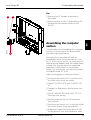
1
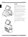
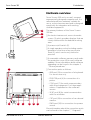
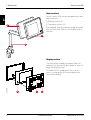
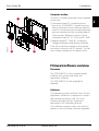
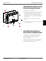
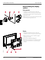
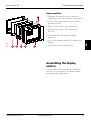
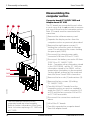
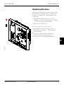
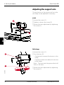
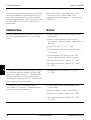
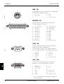
Servo Screen 390
Service Manual
E382 E394E 061 01 02 02
Important
Servo Screen 390
Important
General
The documentation for the Servo Screen 390
consists of:
• Operating Manual
• Service Manual
• Spare Parts List
The Operating Manual is an indispensable
complement to the Service Manual for proper
servicing.
As the Servo Screen 390 is a part of the Servo
Ventilator system, there are also other
documents that can be useful when servicing
the Servo Screen 390:
• Servo Ventilator 300/300A
– Operating Manual
– Service Manual
– Circuit Diagram
– Reference Manual, Computer Interface
• Servo Ventilator 900C/E
– Operating Manual
– Service Manual
– Circuit Diagram
– Reference Manual, SCM 990
Text inside a box is used to highlight
important information.
In addition to the Important information given
here and in the related documents (e. g. in the
Operating Manual), always pay attention to
applicable local and national regulations.
Responsibility for the safe functioning of the
equipment reverts to the owner or user in all
cases in which service or repair has been done
by a non-professional or by persons who are
not employed by or authorized by Siemens,
and when the equipment is used for other than
its intended purpose.
There are two different versions of the Servo
Screen 390:
• Serial No. 10000 or lower – Equipped with
Computer board PC 1662 and a software
memory card of PC Card™-type.
Hazard notices
Make sure that all cables are disconnected
from the connection ports when disassembling
or assembling the Servo Screen 390.
Service
When working with ESD sensitive components, always use a grounded wrist band and
grounded work surface. Adequate service tools
must also be used.
Worn-out batteries must be returned
to the place of purchase or to a place
where they can be safely disposed
of. Batteries must not be disposed
of with ordinary waste. All other
parts shall be discarded according to
hospital rules and in an environPb
mentally safe way.
Functional check
After any service intervention in the Servo
Screen 390, perform a Functional check
according to the instructions in the Operating
Manual.
To responsible service personnel
The contents of this document are not binding.
If any significant difference is found between
the product and this document, please contact
Siemens for further information.
We reserve the right to modify products
without amending this document or advising
the user.
Only personnel authorized by Siemens shall be
permitted to service or repair the Servo Screen
390. Only Siemens-Elema genuine spare parts
must be used. PC boards (spare parts) must
always be kept in a package for sensitive
electronic devices. Siemens will not otherwise
assume responsibility for the materials used,
the work performed, or any possible
consequences of same.
• Serial No. 10001 or higher – Equipped with
Computer board PC 1835 and a software
memory card of CompactFlash™-type.
All information in this Service Manual is valid
for both versions unless stated otherwise.
2
Siemens-Elema AB
E382 E394E 061 01 02 02
Servo Screen 390
Contents
Contents
1. Introduction .......................................................................
5
1
2. Description of functions ...................................................
11
2
3. Disassembly and assembly ..............................................
17
3
4. Service procedures ...........................................................
25
4
5. Troubleshooting ................................................................
37
5
6. Index ..................................................................................
41
6
7. Diagrams ............................................................................
45
7
E382 E394E 061 01 02 02
Siemens-Elema AB
3
Servo Screen 390
Notes
Notes
4
Siemens-Elema AB
E382 E394E 061 01 02 02
Servo Screen 390
1. Introduction
1. Introduction
General .................................................... 6
Hardware overview ................................. 7
Main sections ..................................... 8
Display section ................................... 8
Computer section ............................... 9
Firmware/software overview ................... 9
Firmware ............................................ 9
Software ............................................. 9
E382 E394E 061 01 02 02
Siemens-Elema AB
5
1
Servo Screen 390
1. Introduction
General
Servo Screen 390 is a computer unit that
reads information from a ventilator, makes
calculations, and presents the information to
the operator in a clear, logically organized
manner.
1
The primary purpose of Servo Screen 390 is
to provide a central location for the display of
all parameter information from the ventilator.
It provides information on system and
patient conditions, logically assembled in a
way that presumes presentations including
curves.
Servo Screen 390 does not control the
ventilator or any other medical equipment.
SS-000X
Servo Screen 390 is compatible with the
following ventilator systems:
• Servo Ventilator 300/300A
• Servo Ventilator 900C/E systems that use
Servo Computer Module 990 (SCM 990)
SS-001X
More information about the compatible
ventilators can be found in the chapter
“Technical specifications” in the Operating
Manual.
6
Siemens-Elema AB
E382 E394E 061 01 02 02
1. Introduction
Servo Screen 390
Hardware overview
Servo Screen 390 unit is a small, compact,
ergonomically-designed computer unit. It is
manufactured from materials suitable for
use in a clinical environment and is designed
specifically for integration with existing
ventilator equipment.
3
1
2
The primary features of the Servo Screen
390 are:
• An electro-luminescent, mono-chromatic
screen (1) which provides displays that are
clearly visible within the bedside working
area.
• A power on/off switch (2).
SS-002X
• A single operator control including a pulse
generator in the form of an easy-to-use
knob (3), which can be only turned or
pressed.
• A removable software memory card under
the protective cover (4) for easy software
updates. More information about software
upgrading can be found in the chapter 4,
“Service procedures”.
4
• Connection ports as follows:
– KBD port (5) for connection of a keyboard.
For service use only.
– PRINTER port (6) for connection of a
printer.
– COM port (7) for serial communication
with other equipment. For future applications. Dependent on the software
version.
SS-003X
– VENT port (8) for serial communication
with the ventilator.
– CRT port (9) for connection of an external
monitor.
5
6
7
8
9
10
– PWR port (10) for connection to a power
source.
More information about the connection ports
can be found in the chapter 7, “Diagrams”.
E382 E394E 061 01 02 02
Siemens-Elema AB
7
1
Servo Screen 390
1. Introduction
Main sections
Servo Screen 390 can be separated into two
main sections:
1
• Display section (1)
• Computer section (2)
2
The support arm (3) is always used to mount
the Servo Screen 390 on a ventilator cart or
wall rail.
1
SS-032X
3
Display section
The anti-reflex coated front panel filter (4)
protects the display (5) and makes it easy to
keep the display clean.
SS-033X
To reduce EMC radiation to the environment, a cover plate (6) is mounted at the
rear of the display.
8
4
5
6
Siemens-Elema AB
E382 E394E 061 01 02 02
Servo Screen 390
1. Introduction
Computer section
The two PC boards mounted in the computer
section are:
7
• Computer board (7), containing microprocessor, SS390-BIOS, internal memory
and an interface for the software memory
card. All connection ports except the power
port are mounted on the computer board.
There are two different versions of the
Computer board (7), PC 1662 and PC 1835.
SS-034X
• Adapter board PC 1663 (8), containing
voltage distribution and display interface.
8
9
A fan (9) inside the computer unit provides
forced air cooling for the PC boards. The fan
has a rubber suspension to reduce noise.
Firmware/software overview
Firmware
The SS390-BIOS on the computer board
initializes the system and starts the
application software.
The SS390-BIOS can be upgraded if
required.
Software
The operating system and the Servo Screen
application software is supplied on a removable software memory card. The user
interface provided by this software is
described in the Operating Manual.
The software memory card is very easy to
replace in case of future software upgrades.
E382 E394E 061 01 02 02
Siemens-Elema AB
9
1
Servo Screen 390
1. Introduction
Notes
1
10
Siemens-Elema AB
E382 E394E 061 01 02 02
2. Description of functions
Servo Screen 390
2. Description of functions
General .................................................... 12
Power supply........................................... 12
With Servo Ventilator 300/300A ......... 12
With Servo Ventilator 900C/E ............. 12
Adapter board .......................................... 13
General ............................................... 13
Voltage distribution ............................. 13
Signal adaption ................................... 13
Brightness control .............................. 13
Fan control .......................................... 13
Board identity ..................................... 13
Internal power cable ........................... 13
ON/OFF switch .................................. 14
Display connection cable .................... 14
Fan ..................................................... 14
Computer board ...................................... 14
General ............................................... 14
Software memory card ....................... 15
Battery ................................................ 15
Pulse generator .................................. 16
Connection ports ................................ 16
Display ..................................................... 16
E382 E394E 061 01 02 02
Siemens-Elema AB
11
2
Servo Screen 390
2. Description of functions
General
Power supply
The text in this chapter refers to the block
diagram in chapter 7, “Diagrams” (on the
inside of the back cover).
With Servo Ventilator 300/300A
2
The power supply is connected to the power
inlet port PWR (P21) on Servo Screen 390.
The internal power cable connects the
power inlet port to the ADAPTER BOARD at P18.
The PWR port is described in chapter
7, “Diagrams”.
Power to the Servo Screen 390 is supplied
from the Servo Ventilator 300/300A auxiliary
equipment output N78.
Connector N78 is described (output signals
and limitations) in the Servo Ventilator 300/
300A – Service Manual.
With Servo Ventilator 900C/E
The power supply is connected to the power
inlet port PWR (P21) on Servo Screen 390.
The internal power cable connects the
power inlet port to the ADAPTER BOARD at P18.
The PWR port is described in chapter
7, “Diagrams”.
Power to the Servo Screen 390 is supplied
from an AC Power Adapter 124 when used
with a Servo Ventilator 900C/E.
Technical specifications for the AC Power
Adapter 124:
Mains power supply ........... 100 – 240 V
Mains frequency ................. 50 – 60 Hz
ON/OFF-indication .............. Green LED indicates power on
Output voltage range .......... 24 V DC ±10%
Output power ..................... max. 50 W
Earth leakage current,
normal condition
(IEC 601-1-1) ....................... 30 A
Fuse (internal) ..................... 2.4 A slow
12
Siemens-Elema AB
E382 E394E 061 01 02 02
2. Description of functions
Servo Screen 390
Adapter board
Signal adaption
General
The control signals from the COMPUTER BOARD
PC 1662/PC 1835 to the display are adapted
in this block and furthered to the main block
DISPLAY via P20.
The functional blocks on the ADAPTER BOARD
PC 1663 are:
• VOLTAGE DISTRIBUTION
• SIGNAL ADAPTION
Brightness control
• BRIGHTNESS CONTROL
The brightness in the display can be selected
using the SYSTEM MENU in the application
software. The selected brightness is then
controlled via this block and furthered to the
main block DISPLAY via P19.
• FAN CONTROL
• BOARD IDENTITY
Further functional blocks connected to the
ADAPTER BOARD are:
• INTERNAL POWER CABLE
• ON/OFF SWITCH
When exchanging PC 1663, a setting of the
brightness level may be required, refer to
chapter "3. Disassembly and assembly",
section "Assembling the computer section".
• DISPLAY CONNECTION CABLES
• FAN
Fan control
The ADAPTER BOARD is connected directly to
the COMPUTER BOARD via N5.
An NTC-resistor on PC 1663 senses the air
temperature inside the Servo Screen 390.
Voltage distribution
If the air temperature inside the unit exceeds
approx. 53°C (127°F), the fan is switched on.
When the temperature drops below approx.
45°C (113°F), the fan is switched off.
The inlet power is fused at F1 (3.15 A fast).
Replacing the fuse is described in chapter 4,
“Service procedures”.
The different voltage levels used in the
Servo Screen 390 are regulated by and
distributed from this block.
The distributed voltage levels are:
1. +12 V (±5%), max. 2.6 A. An overvoltage
protection cuts the voltage distribution at
typ. 14.6 V.
2. +5 V (±3%), max. 3.0 A. An overvoltage
protection cuts the voltage distribution at
typ. 6.2 V.
E382 E394E 061 01 02 02
Board identity
PC 1663 is equipped with a BOARD IDENTITY
function that makes it possible for the
COMPUTER BOARD PC 1662/PC 1835 to
recognize the PC 1663 version. This function
is intended for possible future versions, e.g.
new types of displays.
Internal power cable
The internal power cable connects the
PC 1663 (P18) with the power inlet port
PWR (P21).
Siemens-Elema AB
13
2
Servo Screen 390
2. Description of functions
2
ON/OFF switch
Computer board
The ON/OFF SWITCH turns the power supply
to the Servo Screen 390 on or off. This is the
only device for turning the unit on or off. No
other action is needed, e. g. when shutting
down the Servo Screen 390.
General
Display connection cables
The two DISPLAY CONNECTION CABLES connect
the ADAPTER BOARD to the DISPLAY.
One flat cable connects SIGNAL ADAPTION
signals from P20 on PC 1662/PC 1835 to
display connector J1.
One cable connects BRIGHTNESS CONTROL
signals from P19 on PC 1662/PC 1835 to
display connectors J2 and J3.
There are two different versions of the
COMPUTER BOARD:
• PC 1662. Factory mounted on Servo
Screen 390 with Serial No. 10000 or lower.
Software memory card of PC Card™-type
is used.
• PC 1835. Factory mounted on Servo
Screen 390 with Serial No. 10001 or higher.
Software memory card of CompactFlash™type is used.
The two PC boards are interchangable. Refer
to further information in the Spare Parts List
when replacing a PC 1662 with a PC 1835.
The functional blocks on the COMPUTER BOARD
PC 1662/PC 1835 are:
• MICROPROCESSOR
Fan
The Servo Screen 390 is equipped with a
FAN. The fan is controlled by the block FAN
CONTROL.
The purpose of this fan is to provide forced
air cooling inside the unit. The air stream
enters through the ventilation holes in the
lower part of the unit and exits through the
ventilation holes in the upper part of the unit.
– 80486SX, 25 MHz on PC 1662
– Pentium, 166 MHz on PC 1835.
• VGA CONTROLLER
• BUS INTERFACE including:
– Diskette drive interface (not used)
– Hard disk interface (for test purposes
only)
– Two serial ports
– One parallel port
– Keyboard controller
• PULSE GENERATOR INTERFACE
• VOLTAGE & FUNCTION MONITORING
• INTERNAL MEMORY. The size of the internal
memory is optimized for the software
version. The internal memory is mounted
on a standard socket and can be replaced
if required by future software upgrades.
• VIDEO MEMORY
14
Siemens-Elema AB
E382 E394E 061 01 02 02
2. Description of functions
Servo Screen 390
• SRAM (only on PC 1662). This battery
backed up memory contains software
settings (e.g. battery replacement date),
TRENDS and the EVENT LIST.
Note – On PC 1835, TRENDS and EVENT LIST
are stored on the CompactFlash™ card
and thus not dependent on the battery.
• SOFTWARE MEMORY CARD INTERFACE
• SS390-BIOS. Contains low-level software
(BIOS, drivers, start-up screen including
software loading messages and initial
program load of the application software).
There are two different versions of the
SS390-BIOS:
– SS390-PROM mounted on PC 1662.
This PROM is mounted on a PROM
socket and can be upgraded (replaced) if
required.
– SS390-FLASH mounted on PC 1835.
This FLASH memory can be upgraded
(new software downloaded) if required.
Refer to chapter 4, “Service procedures” for
furher information regarding upgrades.
The computer is equipped with procedures
for self-testing and the self-test result can be
displayed in the SERVICE MENU. See chapter
4, “Service procedures”.
Further functional blocks connected to the
COMPUTER BOARD are:
• SOFTWARE MEMORY CARD
• BATTERY
• PULSE GENERATOR
• CONNECTION PORTS
The COMPUTER BOARD is connected directly to
the ADAPTER BOARD via P5.
Software memory card
The SOFTWARE MEMORY CARD contains the
operating system and the Servo Screen 390
application software. Loading of the software into the INTERNAL MEMORY is initialized
by the SS390-BIOS during start-up.
There are two different versions of the
SOFTWARE MEMORY CARD:
2
• PC Card™ used on PC 1662.
• CompactFlash™-card used on PC 1835.
Note – As patient related TRENDS and unit
related EVENT LIST are stored on the
CompactFlash-card, it is not recommended
to move a CompactFlash-card between
different units.
The software on the memory card is
specifically designed for Servo Screen 390,
and cannot be used on a standard PC.
The software memory card is easy to
replace in case of future software upgrades.
See chapter 4, “Service procedures”.
Battery
The lithium BATTERY (3.6 V) is used to back up
the computer setup stored in the CMOSRAM and, for PC 1662, also to back up the
SRAM. If the battery is disconnected,
factory default settings will be used next
time the Servo Screen 390 is started.
The battery must be replaced every three
years. The message ”Replace Servo Screen
390 battery” in the message window
indicates when the battery should be
replaced. A new three-year period will start
when the battery replacement has been
confirmed with the BATTERY CHANGE icon in
the SERVICE MENU.
Replacing the battery and Battery change
confirmation is described in chapter
4, “Service procedures”.
E382 E394E 061 01 02 02
Siemens-Elema AB
15
2. Description of functions
2
Servo Screen 390
Pulse generator
Display
The PULSE GENERATOR with its CONTROL KNOB
(physically mounted as a part of the display
section) is the only necessary device
available to a clinical user for operating the
application software. The pulse generator
itself does not include any functions other
than interaction with the software.
A monochrome electro-illuminating DISPLAY is
used in this version of Servo Screen 390.
Display connection cables connect the
display to the block SIGNAL ADAPTION via
connector J1 and to the block BRIGHTNESS
CONTROL via connectors J2 and J3.
The unit is prepared for possible future
versions with other display types.
Connection ports
All CONNECTION PORTS except the power port
are mounted on the COMPUTER BOARD. More
information about the connection ports can
be found in chapter 7, “Diagrams”.
16
Siemens-Elema AB
E382 E394E 061 01 02 02
3. Disassembly and assembly
Servo Screen 390
Disassembly and assembly
General .................................................... 18
Handling PC boards ................................. 18
Separating the display section
from the computer section ...................... 19
Assembling the display section
with the computer section ....................... 19
Disassembling the display section ........... 20
Pulse generator .................................. 20
Display ................................................ 20
Front panel filter ................................. 21
Assembling the display section ............... 21
Disassembling the computer section ...... 22
Computer board PC 1662/PC 1835
and Adapter board PC 1663................ 22
Fan ..................................................... 23
Assembling the computer section ........... 23
E382 E394E 061 01 02 02
Siemens-Elema AB
17
3
Servo Screen 390
3. Disassembly and assembly
3
General
Handling PC boards
This chapter describes disassembly and
assembly of some of the main parts of the
Servo Screen 390. The drawings in the
Spare parts list are also very useful as a
guide when disassembling and assembling
the Servo Screen 390.
The PC boards contain components that are
highly sensitive to static electricity.
Before disassembling or assembling the
Servo Screen 390, make sure that all
connection cables are disconnected from
the connection ports of Servo Screen
390.
After any service intervention in the
Servo Screen 390, perform a Functional
check according to instructions in the
Operating manual.
Those who come into contact with circuit
boards containing sensitive components
must take certain precautions to avoid
damaging the components (ESD protection).
When working with ESD sensitive
components, always use a grounded wrist
band and grounded work surface. Adequate
service tools must also be used.
PC boards (spare parts) must always be kept
in protective packaging for sensitive
electronic devices.
PC boards must not be
inserted or removed while
power is applied to the PC
boards.
Remove and insert the
PC boards very
carefully to avoid
damage to the
connectors.
18
Siemens-Elema AB
E382 E394E 061 01 02 02
3. Disassembly and assembly
Servo Screen 390
Separating the display section
from the computer section
• Remove the six screws (1).
2
• Carefully separate the display section (2)
from the computer section (3) as much as
is needed to make the pulse generator
connector N12 on PC 1662 and connectors
N1, N2 and N3 at the rear of the display
accessible.
• Disconnect the connectors mentioned
above.
SS-035X
• The display section is now separated from
the computer section.
3
1
Assembling the display section with the computer section
The procedure for assembling the display
section with the computer section is the
reverse of the separation procedure
described above.
Make sure that the rubber sealing strips are
mounted on the display section to obtain a
good seal between the sections.
E382 E394E 061 01 02 02
Siemens-Elema AB
19
3
Servo Screen 390
3. Disassembly and assembly
Disassembling the display
section
Pulse generator
1
• Separate the display section from the
computer section as previously described.
4
3
2
• Pull off the control knob (1) from the pulse
generator shaft.
Display
• Separate the display section from the
computer section as previously described.
4
• Remove the four nuts (1) and the eight
washers (2 and 3).
• Lift off the complete display (4).
• Note the four spacers (5). Make sure that
they are mounted when assembling the
display.
3
SS-037X
3
SS-036X
• Remove the nut (2) and the washer (3) and
lift off the pulse generator (4).
20
5
2
1
Siemens-Elema AB
E382 E394E 061 01 02 02
3. Disassembly and assembly
Servo Screen 390
Front panel filter
2
• Separate the display section from the
computer section as previously described.
• Pull off the control knob from the pulse
generator shaft.
• Remove the rubber sealing strips (1).
• Remove the screws (2) holding the
bars (3).
SS-038X
• Lift off the bars (3) and the copper
plates (4).
• Lift off the support plate (5) including the
display.
6
5
4
3
1
3
• Lift off the front panel filter (6).
Assembling the display
section
The procedure for assembling the display
section is the reverse of the disassembly
procedure described above.
E382 E394E 061 01 02 02
Siemens-Elema AB
21
3. Disassembly and assembly
Servo Screen 390
Disassembling the
computer section
Computer board PC 1662/PC 1835 and
Adapter board PC 1663
2
3
The PC boards are connected to each other
in such a way that its not possible to remove
just one of them from the computer section.
Both PC boards must be removed at the
same time.
4
• Remove the software memory card.
• Separate the display section from the
computer section as previously described.
3
• Remove the eight spacer screws (1)
holding the connection ports to the rear
cover. Do not remove the screws holding
the power port (PWR).
• Disconnect the internal power cable
connector N18 from P18 on PC 1663.
• Disconnect the battery connector N0 from
P13/P14 on PC 1662/PC 1835.
Note – Computer setup information stored
in the CMOS-RAM, and for PC 1662 also
information stored in the SRAM, will be
erased when the battery is disconnected.
Factory default settings will be used next
time the Servo Screen 390 is turned on.
N18
N15
N16
• Remove the two nuts (2) and washers (3).
SS-039X
• Remove the two screws (4) holding
PC 1662/PC 1835.
N0
1
The two different versions of the
computer board are interchangable.
Refer to further information in the Spare
Parts List when replacing a PC 1662 with
a PC 1835.
22
• Carefully lift the PC boards from the
computer section as much as needed to
make the ON/OFF switch connector N15
at P15 and the fan connector N16 at P16
on PC 1663 accessible.
• Disconnect the connectors mentioned
above.
• Lift off the PC boards.
• Carefully separate the computer board
from the adapter board.
Siemens-Elema AB
E382 E394E 061 01 02 02
Servo Screen 390
3. Disassembly and assembly
Fan
2
1
• Remove the PC boards as previously
described.
• Remove the two nuts (1) and washers (2)
holding the fan bracket and lift off the
fan (3).
SS-040X
Assembling the computer
section
3
3
The procedure for assembling the computer
section is the reverse of the disassembly
procedure described above.
Normally the screen area will light up
immediately when the power switch is set
to On. If the screen area is not lit up until the
Startup display appears and the startup beep
sounds, this may be due to an undefined
brightness value stored on the Adapter
board. This may be the case after exchange
of Adapter board PC 1663.
Adjust the brightness setting as follows:
• Set the power switch to On and wait until
the Main menu icons are visible.
• Select SYSTEM DATA and CHANGE SETUP.
• Change the Brightness level (at least one
step).
• Select CHANGE EXIT and SAVE SET-UP.
Save the new setting.
• Set the power switch to Off and wait a
few seconds.
• Set the power switch to On and check that
the screen area is lit up immediately.
• If required, repeat the steps above to set
the Brightness level to the previous value.
E382 E394E 061 01 02 02
Siemens-Elema AB
23
3. Disassembly and assembly
Servo Screen 390
Notes
3
24
Siemens-Elema AB
E382 E394E 061 01 02 02
4. Service procedures
Servo Screen 390
Service procedures
General .................................................... 26
Using the Service Menu .......................... 27
Service access code ........................... 27
Service information display ................. 28
Event list ............................................ 28
Battery change-confirmation ............... 29
Using a keyboard ..................................... 30
Replacing the software memory card ...... 31
Replacing the SS390-PROM
on PC 1662 .............................................. 32
Upgrading the SS390-FLASH
on PC 1835 .............................................. 32
Replacing the internal memory ................ 33
Replacing the battery ............................... 34
Replacing the fuse ................................... 35
Adjusting the support arm ....................... 36
Joint ................................................... 36
Rail clamp ........................................... 36
E382 E394E 061 01 02 02
Siemens-Elema AB
25
4
4. Service procedures
Servo Screen 390
General
This chapter describes, step-by-step, some
service procedures that may be necessary
to perform on the Servo Screen 390. Some
of these service procedures require disassembling the Servo Screen 390. If so,
please see chapter 3, “Disassembly and
assembly” for instructions.
Before disassembling or assembling the
Servo Screen 390, make sure that all
connection cables are disconnected from
the connection ports of Servo Screen
390.
After any service intervention in the
Servo Screen 390, perform a Functional
check according to the instructions in the
Operating manual.
4
26
Siemens-Elema AB
E382 E394E 061 01 02 02
Servo Screen 390
4. Service procedures
Using the Service Menu
The Service Menu serves three purposes:
– It gives access to the Service information
display.
– It gives access to the EVENT LIST.
– It gives access to the BATTERY CHANGE icon.
This icon is selected to confirm that the
Servo Screen 390 battery has been
replaced.
Service Access Code
The Service Access Code is intended only as
a ”separator” between clinical use and
technical use of the Servo Screen 390. It is
not a secret or personal code and it cannot
be changed.
• Select the SERVICE MENU as described in
the Operating Manual.
4
• Enter the Service Access Code on the
numerical entry keypad displayed on the
Servo Screen 390. The Service Access
Code is:
300
• Turn the control knob until the ACCEPT key
is marked.
• Press the control knob. The Service
information display is now shown.
The Service menu icons are also displayed.
E382 E394E 061 01 02 02
Siemens-Elema AB
27
Servo Screen 390
4. Service procedures
Service information display
The Service information display shows some
technical data from the connected ventilator
and from the Servo Screen 390.
If the Servo Screen 390 is connected to a
Servo Ventilator 300/300A, PROM versions
in the SV 300/300A are shown on this
display.
The Service information display will also
show the SS390-BIOS version and the
application software version of the Servo
Screen 390.
Event list
The event list in Servo Screen 390 logs
technical errors, abnormal events and
displayed messages.
4
• Enter the Service Menu, using the Service
Access Code as previously described.
• Turn the control knob until the EVENT LIST
icon is marked.
• Press the control knob. The event list is
now displayed.
• Use the NEXT PAGE and PREV. PAGE icons to
select a page in the event list.
The message string contains up to six
information units:
– Date
– Time
– Event type
– File line
– Error message
– Error code (if available)
28
Siemens-Elema AB
E382 E394E 061 01 02 02
4. Service procedures
Servo Screen 390
Battery change-confirmation
The backup battery in the Servo Screen 390
must be replaced when the information
”Replace Servo Screen 390 battery” is
displayed in the Message window (every
three years). Replacement is described in
the section “Replacing the battery” in this
chapter.
Battery replacement must be confirmed to
remove the ”Replace Servo Screen 390
battery” message. This confirmation also
sets the time used for controlling the
apperance of the message. The message
will appear after startup:
– three years after the latest Battery changeconfirmation or
– if the battery has been disconnected.
Note – It is not recommended to re-connect
a used battery and perform the necessary
Battery change-confirmation. The fixed time
interval until next appearance of the
”Replace Servo Screen 390 battery” is
selected for a fully charged battery.
Confirm battery change as follows:
• Connect the Servo Screen 390 to a
ventilator.
• Start the ventilator and the Servo Screen
390.
• Check that the Time and Date settings
displayed in Servo Screen 390 are correct.
If necessary, adjust according to the
instructions in the Operating Manual.
• Enter the Service Menu, using the Service
Access Code as previously described.
• Turn the control knob until the BATTERY
CHANGE icon is marked.
• Press the control knob. The battery
replacement is now confirmed. The
message in the Message window will
disappear immediately, but the BATTERY
CHANGE icon will not disappear until another
menu is selected.
E382 E394E 061 01 02 02
Siemens-Elema AB
29
4
Servo Screen 390
4. Service procedures
Using a keyboard
A standard AT keyboard can be connected
to the Servo Screen 390.
When the keyboard is connected, it is ready
for use. No setting is needed. The keyboard
can be used as a substitute for the control
knob/pulse generator, but it can also be used
in combination with the control knob/pulse
generator.
The following keys are used to simulate the
control knob:
• Left-arrow key = Turning the control knob
counter-clockwise.
• Right-arrow key = Turning the control knob
clockwise.
• Enter key = Pressing the control knob.
The keyboard can be used when troubleshooting a possible malfunction in the
control knob function, for example. If there is
a malfunction when using the control knob/
pulse generator and this malfunction does
not appear when using a connected
keyboard, the error may be in the pulse
generator or in the pulse generator interface.
4
The keyboard can also be used in combination with the ”on-screen keyboard” when
entering or changing a patient ID. Only upper
case letters will be displayed in the Patient
ID field.
30
Siemens-Elema AB
E382 E394E 061 01 02 02
4. Service procedures
Servo Screen 390
Replacing the software
memory card
• Make sure that the Servo Screen 390 is
turned off.
• Remove the protective cover (1).
2
• Push the button (2) to release the software
memory card from the memory card slot.
• Pull out the software memory card (3).
3
• Put the desired software memory card
into the memory card slot. A mechanical
key on the card and in the slot prevents it
from being fully inserted in a wrong
position.
• Push the software memory card into the
slot. Mount the protective cover (1).
SS-041X
1
The software memory card is now replaced.
Perform a Functional check according to the
instructions in the Operating Manual.
There are two different versions of the
software memory card:
– PC Card™ used on Servo Screen 390
equipped with Computer board PC 1662.
– CompactFlash™ used on Servo Screen
390 equipped with Computer board
PC 1835. Note – As patient related TRENDS
and unit related EVENT LIST are stored on
the CompactFlash-card, it is not
recommended to move a CompactFlashcard between different units.
The procedure for replacing the software
memory card is the same for the two
different versions
E382 E394E 061 01 02 02
Siemens-Elema AB
31
4
Servo Screen 390
4. Service procedures
Replacing the SS390-PROM
on PC 1662
Before performing this service action, read
the sections “General” and “Handling PC
boards” in chapter 3, “Disassembly and
assembly”.
• Remove the PC boards as described in
chapter 3, “Disassembly and assembly”.
• Use an extraction tool to remove the old
SS390-PROM (1) mounted at the rear of
PC 1662.
• Mount the new SS390-PROM into the
socket. Make sure that it is correctly
mounted and that no leg has been bent or
broken.
SS-042X
4
• Assemble the Servo Screen 390 as
described in chapter 3, “Disassembly and
assembly”.
1
The SS390-PROM is now replaced.
Perform a Functional check according to the
instructions in the Operating Manual.
Upgrading the SS390-FLASH
on PC 1835
A Service CompactFlash™-card will be used
to upgrade the SS390-FLASH on PC 1835.
Upgrade instructions will be delivered with
this Service card.
32
Siemens-Elema AB
E382 E394E 061 01 02 02
4. Service procedures
Servo Screen 390
Replacing the internal
memory
Before performing this service action, read
the sections “General” and “Handling PC
boards” in chapter 3, “Disassembly and
assembly”.
Note – This procedure and illustration shows
SIMM chip on PC 1662. The board PC 1835
is equipped with a different type of SIMM
chip but the replacement procedure is still
the same. PC 1835 is also prepared for and
can, in the future, be equipped with SIMM
chips mounted on the rear side of the PC
board. If so, the PC board does not have to
be removed when replacing the internal
memory.
• Remove the PC boards as described in
chapter 3, “Disassembly and assembly”.
4
SS-053X
• Remove the old SIMM chip (1) mounted
on PC 1662/PC 1835.
• Mount the new SIMM chip into the
socket.
1
• Assemble the Servo Screen 390 as
described in chapter 3, “Disassembly and
assembly”.
The internal memory is now replaced.
Perform a Functional check according to the
instructions in the Operating Manual.
E382 E394E 061 01 02 02
Siemens-Elema AB
33
Servo Screen 390
4. Service procedures
Replacing the battery
P1
3
3 P
14
When the information ”Replace Servo
Screen 390 battery” is displayed in the
Message window, the battery must be
replaced.
• Make sure that the Servo Screen 390 is
turned off.
2
• Loosen the two screws (1).
• Carefully lift off the battery cover including
battery (2), but do not remove the cable
connector (3) from PC 1662/PC 1835.
Note – Computer setup information stored
in the CMOS-RAM, and for PC 1662 also
information stored in the SRAM, will be
erased if the connector is removed. In that
case, factory default settings will be used
next time the Servo Screen 390 is turned
on.
1
4
4
• There are two equal battery connectors
connected in parallell (P13 and P14) on
PC 1662/PC 1835. Connect the new
battery (4) to the unused connector. The
battery backup functions are now secured
by the new battery.
• Cut the cable tie holding the old battery to
the battery cover. Mount the battery cover
to the new battery using a new cable tie.
P1
3 P
14
• Disconnect and remove the old battery.
• Mount the battery cover including battery
on Servo Screen 390.
SS-043X
The old battery must be disposed of
according to local or national regulations.
34
Battery replacement must be confirmed in
the SERVICE MENU within the application
software. This is described in the section
“Using the Service Menu” in this chapter.
The battery is now replaced. Perform a
Functional check according to the
instructions in the Operating Manual.
Siemens-Elema AB
E382 E394E 061 01 02 02
4. Service procedures
Servo Screen 390
Replacing the fuse
Before performing this service action, read
the sections “General” and “Handling PC
boards” in chapter 3, “Disassembly and
assembly”.
1
• Separate the display section from the
computer section as described in chapter
3, “Disassembly and assembly”.
• Remove the old fuse (1).
• Insert a new fuse, 3.15 A fast.
• Assemble the Servo Screen 390 as
described in chapter 3, “Disassembly
and assembly”.
The fuse is now replaced. Perform a
Functional check according to the
instructions in the Operating Manual.
SS-044X
4
E382 E394E 061 01 02 02
Siemens-Elema AB
35
Servo Screen 390
4. Service procedures
Adjusting the support arm
The pre-tension in the joint as well as in the
rail clamp can be adjusted if necessary:
Joint
• Loosen the screw (1).
2
• Tighten or loosen the screw (2).
• Secure the new adjustment by tightening
the screw (1).
Rail clamp
• Loosen the screw (1).
1
• Turn the lever (2):
– Clockwise to increase the tension in the
clamp.
– Counter-clockwise to reduce the tension
in the clamp.
2
Note – The lever must be given either half
turns or full turns.
• Secure the new adjustment by tightening
the screw (1).
SS-045X
4
SS-046X
1
36
Siemens-Elema AB
E382 E394E 061 01 02 02
5. Troubleshooting
Servo Screen 390
Troubleshooting
5
E382 E394E 061 01 02 02
Siemens-Elema AB
37
Servo Screen 390
5. Troubleshooting
Before starting troubleshooting, try to eliminate all possibilities of operational errors. If
the malfunction remains, use the troubleshooting guide below. Perform actions step
by step and check that the malfunction is
eliminated.
When the fault is corrected, carry out a
Functional check as described in the
Operating Manual, chapter 4, “Startup and
shutdown”.
Malfunction
Action
Servo Screen 390 will not start. The display
is not illuminated and there is no start-up
beep.
• Check/replace the external power cable/
connectors.
• Check that the power supply source
(ventilator or external power supply) works
properly.
• Check the fuse F1 on PC 1663.
• Check/replace the internal power cable/
connectors.
• Check/replace the Servo Screen 390
power switch and its cable/connector.
• If none of the above, replace PC 1663.
• If none of the above, replace PC 1662/
PC 1835.
5
The display is illuminated at power on and
one or more start-up beeps can be heard
within 20 s after power on. Thereafter the
display may flash or will be completely
illuminated. A connected CRT display is not
illuminated and shows no text.
• Hardware failure. Replace PC 1662/
PC 1835.
The display is not illuminated, but a
connected CRT display is illuminated and
shows the start-up sequence.
• Check/replace the display power and
signal cables.
• If not the above, replace the display.
• If none of the above, replace PC 1663.
• If none of the above, replace PC 1662/
PC 1835.
38
Siemens-Elema AB
E382 E394E 061 01 02 02
Servo Screen 390
5. Troubleshooting
Malfunction
Action
The display is illuminated during start-up, but
after the start-up beep it goes black or shows
a deformed image. A connected CRT display
shows a normal start-up sequence and
image.
• Check/replace the signal cable between
PC 1663 and the display.
The start-up logo does not disappear and:
• Replace the software memory card.
– the message “LOADING SOFTWARE“ does not
disappear within 30 s or
• If not the above, replace PC 1662/PC 1835.
• If not the above, replace the display.
– the message “SOFTWARE MISSING“ appears.
The control knob does not work properly.
• Operate the Servo Screen 390 with a
connected keyboard:
– If it works with the connected keyboard:
1. Replace the control knob.
2. If not the above, replace PC 1662/
PC 1835.
– If it does not work with the connected
keyboard:
1. Replace PC 1662/PC 1835.
The brightness of the display can not be
adjusted.
5
• Check the power cable from PC 1663 to
the internal display.
• If not the above, replace PC 1663.
• If none of the above, replace the display.
It is not possible to establish communication
between Servo Screen 390 and an SV 300/
300A or an SV 900C/E.
• Check/replace the communication cable.
• Try to communicate with another
ventilator (on SV 900C/E, first make sure
that the SCM 990 is properly configured).
• If none of the above, replace PC 1662/
PC 1835.
E382 E394E 061 01 02 02
Siemens-Elema AB
39
5. Troubleshooting
Servo Screen 390
Malfunction
Action
It is not possible to print out on the
connected printer.
• Check/replace the printer cable.
• Make sure that the printer itself is properly
configured.
• Make sure that the connected printer is
selected in the printer list in Servo Screen
390.
• Try to connect another printer.
• If none of the above, replace PC 1662/
PC 1835.
Information message ”Replace Servo
Screen 390 battery” remains in the
Message window although the battery has
been replaced.
5
• Confirm the battery replacement using the
BATTERY CHANGE icon in the Service Menu.
• If not the above, replace PC 1662/PC 1835.
It is not possible to set Time or Date in
Servo Screen when connected to a SV 300/
300A.
• Make sure that the communication cable
between Servo Screen and SV 300/300A
is connected to N82 on SV 300/300A.
The Servo Screen 390 starts up, but does
not display any information (e.g. curves or
numerical values) from the SV 300/300A.
• Reset the memory in SV 300/300A-PC
1587. See SV 300/300A – Service Manual
(printed 1996 or later).
40
Siemens-Elema AB
E382 E394E 061 01 02 02
6. Index
Servo Screen 390
Index
6
E382 E394E 061 01 02 02
Siemens-Elema AB
41
Adapter board PC 1663
AC Power Adapter 124
9
Fan
Fan control
Firmware
Front panel filter
Fuse
13 22
12
B
Battery
Battery change-icon
Battery replacement
Board identity
Brightness control
Bus interface
6
29
34
13
13
14
42
9
8
Service procedures
Disassembly and assembly
21
13
35
H
Handling PC boards
18
Internal memory
Internal power cable
14
13
33
7
9
9
9
7
7
7
15
31
14 22
14 22
22
16
15
K
KBD port
Keyboard
7
30
M
Microprocessor
7
8
14
O
16 20
14
20
On/off switch
7
14
P
E
ESD protection
Event list
14 23
13
I
D
Display
Display connection cables
Display section
9
15
C
COM port
CompactFlash Card
Computer board PC 1662
Computer board PC 1835
Computer section
Connection ports
Control knob
CTR port
F
Description of functions
Service procedures
Disassembly and assembly
Description of functions
Introduction
A
Introduction
Servo Screen 390
6. Index
18
15
28
PC Card
Power supply
PRINTER port
Protective cover
Pulse generator
Pulse generator interface
PWR port
Siemens-Elema AB
15
12
7
7
7
31
31
16 20
14
7
E382 E394E 061 01 02 02
6. Index
Service access code
Service information display
Service menu
Signal adaption
Software
Software memory card
Software mem. card interface
SRAM
SS390-BIOS
SS390-FLASH
SS390-PROM
Support arm
Support arm joint
Support arm rail clamp
Service procedures
Disassembly and assembly
Description of functions
S
Introduction
Servo Screen 390
27
28
27
13
9
7
9
15
15
15
15
15
15
31
32
32
8
36
36
V
VENT port
Video memory
VGA controller
Voltage distribution
Voltage & Function monitoring
7
9
14
14
13
14
6
E382 E394E 061 01 02 02
Siemens-Elema AB
43
Servo Screen 390
6. Index
Notes
6
44
Siemens-Elema AB
E382 E394E 061 01 02 02
7. Diagrams
Servo Screen 390
Diagrams
7
E382 E394E 061 01 02 02
Siemens-Elema AB
45
Servo Screen 390
7. Diagrams
KBD – N6
Keyboard port for connection of a keyboard.
DIN 41524, female, 5 pole.
2
5
4
1
2
3
3
SS-048X
1
KEY_CLK
KEY_DATA
–
4
GND
5
+5 V
A* CHASSIS_GND
PRINTER – N7
SS-049X
13
1
14
25
Printer port for connection of a printer.
D-Sub, female, 25 pole.
1
2
3
4
5
6
7
8
9
10
11
12
13
LPT_STROBE.L
LPT_PD_0
LPT_PD_1
LPT_PD_2
LPT_PD_3
LPT_PD_4
LPT_PD_5
LPT_PD_6
LPT_PD_7
LPT_ACK.L
LPT_BUSY
LPT_PE
LPT_SLCT
14
15
16
17
18
19
20
21
22
23
24
25
A*
LPT_AUTOFD_L
LPT_ERROR.L
LPT_INIT.L
LPT_SLCTIN.L
GND
GND
GND
GND
GND
GND
GND
GND
CHASSIS_GND
COM – P8
SS-050X
1
Serial communication port for communication with other equipment.
D-Sub, male, 9 pole. (For future applications. Dependent on the software version.)
5
6
9
1
2
3
4
5
DCD_1A
RXD_1A
TXD_1A
DTR_1A
GND
6
7
8
9
A*
DSR_1A
RTS_1A
CTS_1A
RI_1A
CHASSIS_GND
CRT – N10
5
1
7
SS-051X
10
6
15
11
CRT port for connection of an external
monitor. HD D-Sub, female, 15 pole.
1
2
3
4
5
6
7
8
RED_CRT
GREEN_CRT
BLUE_CRT
–
GND
0 VA
0 VA
0 VA
9
10
11
12
13
14
15
A*
–
GND
–
–
HSYNC_CRT
VSYNC_CRT
–
CHASSIS_GND
* A = Connected to the metal housing of
the connector.
46
Siemens-Elema AB
E382 E394E 061 01 02 02
7. Diagrams
Servo Screen 390
VENT – P9
SS-050X
1
1
2
3
4
5
9
6
7
8
9
A*
DSR_2A
RTS_2A
CTS_2A
RI_2A
CHASSIS_GND
N82
Communication cable between
SS 390 and SV 300/300A
9-pin connector
26-pin connector
pin #
pin #
5 ---------- BN ----------- 2
8 ---------- RD ----------- 3
2 ---------- WH ---------- 4
3 ---------- BU ----------- 5
7 ---------- GN ----------- 6
6 ----------- YE ----------- 7
DCD_2A
RXD_2A
TXD_2A
DTR_2A
GND
Communication cable between
SS 390 – SCM 990
9-pin connector
26-pin connector
pin #
pin #
1 ---------- GN ----------- 4
2 ----------- YE ----------- 2
3 ---------- GY ----------- 3
4 ----------- PK --------- 5,6
5 ---------- BU ----------- 7
6,8 --------- WH --------- 20
7 ---------- RD ----------- 8
RS232C – N1
VENT – P9
6
VENT – P9
Serial communication port for communication with the Servo Ventilator.
D-Sub, male, 9 pole.
5
PWR – P21
9
PWR – P21
Power port for connection to a 24V power
source. D-Sub, male, 15 pole.
8
15
24 V power cable between
SS 390 and SV 300/300A or
SS 390 and AC Power Adapter 124
15-pin connector 15-pin connector
pin #
pin #
7 ----------- YE ----------- 7
8 ---------- GN ----------- 8
1 ---------- BN ----------- 1
2 ---------- WH ---------- 2
N78 on
SV 300/300A
SS-052X
1
1
2
3
4
5
6
7
8
+24 V
+24 V
–
–
–
–
GND
GND
9
10
11
12
13
14
15
A*
–
–
–
–
–
–
–
CHASSIS_GND
7
* A = Connected to the metal housing of
the connector.
E382 E394E 061 01 02 02
Siemens-Elema AB
47
7. Diagrams
CONTROL
KNOB
PULSE
GENERATOR
DISPLAY
J3
N3
J1
N1
J2
N2
DISPLAY SECTION
ON-OFF
SWITCH
FAN
N15
P15
VOLTAGE
DISTRIBUTION
+12V
VGA
CONTROLLER
SIGNAL
ADAPTION
BRIGHTNESS
CONTROL
VIDEO
MEMORY
VOLTAGE &
FUNCTION
MONITORING
SS-047E
P19
N19
CONNECTION PORTS:
P21
PWR
If connected
to SV 300/300A
N10
P9
CRT
VENT
24V POWER CABLE
From
SV 300/300A
BUS
INTERFACE
SOFTWARE
MEMORY
CARD
INTERFACE
AC POWER
ADAPTER
124
SS390-BIOS
P14
N20
P20
SRAM
P13
FAN
CONTROL
BOARD
IDENTITY
P5
+5V
MICROPROCESSOR
P16
N16
F1
N0
N0
BATTERY
SOFTWARE
MEMORY CARD
(PC Card or
CompactFlash Card)
PULSE
GENERATOR
INTERFACE
P8
N7
COM
PRINTER
7
P12
N12
INTERNAL MEMORY
COMPUTER BOARD PC 1662 / PC 1835
N5
N18
P18
INTERNAL POWER CABLE
DISPLAY CONNECTION CABLES
ADAPTER BORD
PC1663
COMPUTER SECTION
N6
KBD
If connected
to SV 900C/E
Servo Screen 390 – Block diagram
Servo Screen 390 – Service Manual
Order No.: 63 14 251 E394E
© Siemens-Elema AB, Electromedical Systems Division, 1995-2000. All rights reserved. No part of this
publication may be reproduced, stored in a retrieval system, or transmitted in any form or by any means,
electronic, mechanical, photocopying, recording, or otherwise, without the prior permission of the copyright
owner in writing. Subject to alterations without prior notice.
Issued by Siemens-Elema AB, Electromedical Systems Division, SE-171 95 Solna, Sweden.
E382 E394E 061 01 02 02
Printed in Sweden
Price group: 5
0600 0.5
2nd English edition,
June 2000