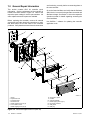
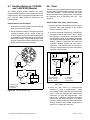
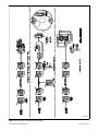
1
Service Marine Generator Sets Models: 6EKOD 5EFKOD 9--11EKOZD 7--9EFKOZD TP-6774 2/14a Product Identification Information Product identification numbers determine service parts. Record the product identification numbers in the spaces below immediately after unpacking the products so that the numbers are readily available for future reference. Record field-installed kit numbers after installing the kits. Generator Set Identification Numbers Record the product identification numbers from the generator set nameplate(s). Model Designation Specification Number Serial Number Accessory Number Accessory Description Engine Identification Record the product identification information from the engine nameplate. Manufacturer Model Designation Serial Number x:in:007:001 2 TP-6774 2/14a Table of Contents Safety Precautions and Instructions . . . . . . . . . . . . . . . . . . . . . . . . . . . . . . . . . . . . . . . . . . . . . . . . . . . . . . . . . 7 Introduction . . . . . . . . . . . . . . . . . . . . . . . . . . . . . . . . . . . . . . . . . . . . . . . . . . . . . . . . . . . . . . . . . . . . . . . . . . . . . . . 11 Service Assistance . . . . . . . . . . . . . . . . . . . . . . . . . . . . . . . . . . . . . . . . . . . . . . . . . . . . . . . . . . . . . . . . . . . . . . . . . 11 Section 1 Specifications . . . . . . . . . . . . . . . . . . . . . . . . . . . . . . . . . . . . . . . . . . . . . . . . . . . . . . . . . . . . . . . . . . . 1.1 General . . . . . . . . . . . . . . . . . . . . . . . . . . . . . . . . . . . . . . . . . . . . . . . . . . . . . . . . . . . . . . 1.2 Engine . . . . . . . . . . . . . . . . . . . . . . . . . . . . . . . . . . . . . . . . . . . . . . . . . . . . . . . . . . . . . . . 1.3 Generator, 4 Lead . . . . . . . . . . . . . . . . . . . . . . . . . . . . . . . . . . . . . . . . . . . . . . . . . . . . . 1.4 Generator, 12 Lead . . . . . . . . . . . . . . . . . . . . . . . . . . . . . . . . . . . . . . . . . . . . . . . . . . . . 1.5 Service Views . . . . . . . . . . . . . . . . . . . . . . . . . . . . . . . . . . . . . . . . . . . . . . . . . . . . . . . . . 1.6 Torque Specifications . . . . . . . . . . . . . . . . . . . . . . . . . . . . . . . . . . . . . . . . . . . . . . . . . . 13 13 14 15 15 16 17 Section 2 Scheduled Maintenance . . . . . . . . . . . . . . . . . . . . . . . . . . . . . . . . . . . . . . . . . . . . . . . . . . . . . . . . . . 2.1 General . . . . . . . . . . . . . . . . . . . . . . . . . . . . . . . . . . . . . . . . . . . . . . . . . . . . . . . . . . . . . . 2.2 Lubrication System . . . . . . . . . . . . . . . . . . . . . . . . . . . . . . . . . . . . . . . . . . . . . . . . . . . . 19 19 20 Section 3 Exhaust System . . . . . . . . . . . . . . . . . . . . . . . . . . . . . . . . . . . . . . . . . . . . . . . . . . . . . . . . . . . . . . . . . . 3.1 Exhaust System Inspection . . . . . . . . . . . . . . . . . . . . . . . . . . . . . . . . . . . . . . . . . . . . . 3.2 Servicing Mixing Elbow . . . . . . . . . . . . . . . . . . . . . . . . . . . . . . . . . . . . . . . . . . . . . . . . . 21 21 21 Section 4 Fuel System . . . . . . . . . . . . . . . . . . . . . . . . . . . . . . . . . . . . . . . . . . . . . . . . . . . . . . . . . . . . . . . . . . . . . 4.1 General . . . . . . . . . . . . . . . . . . . . . . . . . . . . . . . . . . . . . . . . . . . . . . . . . . . . . . . . . . . . . . 4.2 Fuel Filter . . . . . . . . . . . . . . . . . . . . . . . . . . . . . . . . . . . . . . . . . . . . . . . . . . . . . . . . . . . . . 4.2.1 Fuel System Bleed . . . . . . . . . . . . . . . . . . . . . . . . . . . . . . . . . . . . . . . . . . . . . 4.3 Fuel Pump . . . . . . . . . . . . . . . . . . . . . . . . . . . . . . . . . . . . . . . . . . . . . . . . . . . . . . . . . . . . 4.4 Governor . . . . . . . . . . . . . . . . . . . . . . . . . . . . . . . . . . . . . . . . . . . . . . . . . . . . . . . . . . . . . 4.5 Fuel Solenoid . . . . . . . . . . . . . . . . . . . . . . . . . . . . . . . . . . . . . . . . . . . . . . . . . . . . . . . . . 23 23 23 24 25 25 25 Section 5 Cooling System . . . . . . . . . . . . . . . . . . . . . . . . . . . . . . . . . . . . . . . . . . . . . . . . . . . . . . . . . . . . . . . . . . 5.1 General . . . . . . . . . . . . . . . . . . . . . . . . . . . . . . . . . . . . . . . . . . . . . . . . . . . . . . . . . . . . . . 5.2 Water-Cooled Exhaust Manifold . . . . . . . . . . . . . . . . . . . . . . . . . . . . . . . . . . . . . . . . . 5.3 Coolant Replacement Including Heat Exchanger Service . . . . . . . . . . . . . . . . . . . . 5.4 Check and Fill Coolant . . . . . . . . . . . . . . . . . . . . . . . . . . . . . . . . . . . . . . . . . . . . . . . . . 5.5 Flush and Clean Cooling System . . . . . . . . . . . . . . . . . . . . . . . . . . . . . . . . . . . . . . . . 5.6 Pressure Cap . . . . . . . . . . . . . . . . . . . . . . . . . . . . . . . . . . . . . . . . . . . . . . . . . . . . . . . . . 5.7 Impeller Inspection and Replacement . . . . . . . . . . . . . . . . . . . . . . . . . . . . . . . . . . . . 5.8 Belt Tension . . . . . . . . . . . . . . . . . . . . . . . . . . . . . . . . . . . . . . . . . . . . . . . . . . . . . . . . . . . 5.8.1 Seawater Pump Belt Tensioning Procedure . . . . . . . . . . . . . . . . . . . . . . . 5.9 Anticorrosion Zinc Anode . . . . . . . . . . . . . . . . . . . . . . . . . . . . . . . . . . . . . . . . . . . . . . . 5.10 Siphon Break . . . . . . . . . . . . . . . . . . . . . . . . . . . . . . . . . . . . . . . . . . . . . . . . . . . . . . . . . 27 27 28 28 31 32 32 32 33 33 34 35 Section 6 Troubleshooting . . . . . . . . . . . . . . . . . . . . . . . . . . . . . . . . . . . . . . . . . . . . . . . . . . . . . . . . . . . . . . . . . 6.1 Introduction . . . . . . . . . . . . . . . . . . . . . . . . . . . . . . . . . . . . . . . . . . . . . . . . . . . . . . . . . . . 6.2 Initial Checks . . . . . . . . . . . . . . . . . . . . . . . . . . . . . . . . . . . . . . . . . . . . . . . . . . . . . . . . . . 6.3 Troubleshooting Chart . . . . . . . . . . . . . . . . . . . . . . . . . . . . . . . . . . . . . . . . . . . . . . . . . . 37 37 37 37 Section 7 Controller 7.1 7.2 7.3 7.4 7.5 43 43 44 45 45 47 47 48 49 49 51 TP-6774 2/14a ....................................................................... Introduction . . . . . . . . . . . . . . . . . . . . . . . . . . . . . . . . . . . . . . . . . . . . . . . . . . . . . . . . . . . General Repair Information . . . . . . . . . . . . . . . . . . . . . . . . . . . . . . . . . . . . . . . . . . . . . SiteTecht Software . . . . . . . . . . . . . . . . . . . . . . . . . . . . . . . . . . . . . . . . . . . . . . . . . . . . Controller Service Replacement Kit GM83745 . . . . . . . . . . . . . . . . . . . . . . . . . . . . . Advanced Digital Control IId Operation . . . . . . . . . . . . . . . . . . . . . . . . . . . . . . . . . . . 7.5.1 Controls and Indicators . . . . . . . . . . . . . . . . . . . . . . . . . . . . . . . . . . . . . . . . . 7.5.2 Starting the Generator Set . . . . . . . . . . . . . . . . . . . . . . . . . . . . . . . . . . . . . . 7.5.3 Stopping the Generator Set . . . . . . . . . . . . . . . . . . . . . . . . . . . . . . . . . . . . . 7.5.4 Fault Shutdowns and Warnings . . . . . . . . . . . . . . . . . . . . . . . . . . . . . . . . . . 7.5.5 Digital Display . . . . . . . . . . . . . . . . . . . . . . . . . . . . . . . . . . . . . . . . . . . . . . . . . Table of Contents 3 7.5.6 Controller Fault Diagnostics . . . . . . . . . . . . . . . . . . . . . . . . . . . . . . . . . . . . . Communication Port . . . . . . . . . . . . . . . . . . . . . . . . . . . . . . . . . . . . . . . . . . . . . . . . . . . Fuses . . . . . . . . . . . . . . . . . . . . . . . . . . . . . . . . . . . . . . . . . . . . . . . . . . . . . . . . . . . . . . . . Preheat Relay . . . . . . . . . . . . . . . . . . . . . . . . . . . . . . . . . . . . . . . . . . . . . . . . . . . . . . . . . Battery Charging Module . . . . . . . . . . . . . . . . . . . . . . . . . . . . . . . . . . . . . . . . . . . . . . . Controller Logic Specifications . . . . . . . . . . . . . . . . . . . . . . . . . . . . . . . . . . . . . . . . . . . 7.10.1 Fault Shutdown and Warning Specifications . . . . . . . . . . . . . . . . . . . . . . . 7.10.2 Controller Resetting (Following System Fault Shutdown) . . . . . . . . . . . . 7.10.3 Voltage Regulator and Calibration Specifications . . . . . . . . . . . . . . . . . . . 7.10.4 Voltage Regulator Adjustments . . . . . . . . . . . . . . . . . . . . . . . . . . . . . . . . . . 7.10.5 System Fault Warning Lamp with Digital Displays . . . . . . . . . . . . . . . . . . 7.10.6 System Fault Shutdown Lamp With Digital Displays . . . . . . . . . . . . . . . . 7.10.7 Status and Notice Digital Displays . . . . . . . . . . . . . . . . . . . . . . . . . . . . . . . 7.11 Menu Displays . . . . . . . . . . . . . . . . . . . . . . . . . . . . . . . . . . . . . . . . . . . . . . . . . . . . . . . . 7.12 Monitoring and Programming Setup . . . . . . . . . . . . . . . . . . . . . . . . . . . . . . . . . . . . . . 7.12.1 PC Communications . . . . . . . . . . . . . . . . . . . . . . . . . . . . . . . . . . . . . . . . . . . 7.13 Reviewing Menu Displays . . . . . . . . . . . . . . . . . . . . . . . . . . . . . . . . . . . . . . . . . . . . . . . 7.13.1 Error Messages . . . . . . . . . . . . . . . . . . . . . . . . . . . . . . . . . . . . . . . . . . . . . . . 7.13.2 Overview . . . . . . . . . . . . . . . . . . . . . . . . . . . . . . . . . . . . . . . . . . . . . . . . . . . . . 7.13.3 Engine Metering . . . . . . . . . . . . . . . . . . . . . . . . . . . . . . . . . . . . . . . . . . . . . . . 7.13.4 Generator Metering (and Calibration) . . . . . . . . . . . . . . . . . . . . . . . . . . . . . 7.13.5 GenSet Information . . . . . . . . . . . . . . . . . . . . . . . . . . . . . . . . . . . . . . . . . . . . 7.13.6 GenSet Run Time . . . . . . . . . . . . . . . . . . . . . . . . . . . . . . . . . . . . . . . . . . . . . 7.13.7 GenSet System . . . . . . . . . . . . . . . . . . . . . . . . . . . . . . . . . . . . . . . . . . . . . . . 7.13.8 Voltage Regulator . . . . . . . . . . . . . . . . . . . . . . . . . . . . . . . . . . . . . . . . . . . . . . 7.13.9 Event Log . . . . . . . . . . . . . . . . . . . . . . . . . . . . . . . . . . . . . . . . . . . . . . . . . . . . 7.13.10 Prime Menu . . . . . . . . . . . . . . . . . . . . . . . . . . . . . . . . . . . . . . . . . . . . . . . . . . . 7.13.11 Volt Select . . . . . . . . . . . . . . . . . . . . . . . . . . . . . . . . . . . . . . . . . . . . . . . . . . . . 7.13.12 USB Flowchart . . . . . . . . . . . . . . . . . . . . . . . . . . . . . . . . . . . . . . . . . . . . . . . . 53 55 55 55 56 56 56 60 60 60 61 62 63 64 66 66 66 66 67 67 68 69 69 69 70 70 71 71 72 Section 8 Component Testing and Adjustment . . . . . . . . . . . . . . . . . . . . . . . . . . . . . . . . . . . . . . . . . . . . . . . 8.1 Theory of Operation . . . . . . . . . . . . . . . . . . . . . . . . . . . . . . . . . . . . . . . . . . . . . . . . . . . . 8.2 Separate Excitation . . . . . . . . . . . . . . . . . . . . . . . . . . . . . . . . . . . . . . . . . . . . . . . . . . . . 8.3 Exciter Field (9--11EKOZD/7--9EFKOZD Models) . . . . . . . . . . . . . . . . . . . . . . . . . . 8.4 Exciter Armature (9--11EKOZD and 7--9EFKOZD Models) . . . . . . . . . . . . . . . . . . . 8.5 Slip Rings (6EKOD/5EFKOD Models) . . . . . . . . . . . . . . . . . . . . . . . . . . . . . . . . . . . . 8.6 Brushes (6EKOD/5EFKOD Models) . . . . . . . . . . . . . . . . . . . . . . . . . . . . . . . . . . . . . . 8.7 Rectifier Module (9--11EKOZD and 7--9EFKOZD Models) . . . . . . . . . . . . . . . . . . . 8.8 Rotor . . . . . . . . . . . . . . . . . . . . . . . . . . . . . . . . . . . . . . . . . . . . . . . . . . . . . . . . . . . . . . . . . 8.9 Stator . . . . . . . . . . . . . . . . . . . . . . . . . . . . . . . . . . . . . . . . . . . . . . . . . . . . . . . . . . . . . . . . 8.10 Voltage Regulator . . . . . . . . . . . . . . . . . . . . . . . . . . . . . . . . . . . . . . . . . . . . . . . . . . . . . . 8.10.1 Voltage Regulator and Calibration Specifications . . . . . . . . . . . . . . . . . . . 8.10.2 Voltage Regulator Adjustments . . . . . . . . . . . . . . . . . . . . . . . . . . . . . . . . . . 8.10.3 Voltage Regulator . . . . . . . . . . . . . . . . . . . . . . . . . . . . . . . . . . . . . . . . . . . . . . 8.11 Voltage Reconnection . . . . . . . . . . . . . . . . . . . . . . . . . . . . . . . . . . . . . . . . . . . . . . . . . . 8.12 Four-Lead Reconnection . . . . . . . . . . . . . . . . . . . . . . . . . . . . . . . . . . . . . . . . . . . . . . . 8.12.1 100--120-Volt Configurations . . . . . . . . . . . . . . . . . . . . . . . . . . . . . . . . . . . . 8.12.2 100--120/200--240-Volt Configurations . . . . . . . . . . . . . . . . . . . . . . . . . . . . 8.12.3 200--240-Volt Configurations . . . . . . . . . . . . . . . . . . . . . . . . . . . . . . . . . . . . 8.13 Twelve-Lead Reconnection . . . . . . . . . . . . . . . . . . . . . . . . . . . . . . . . . . . . . . . . . . . . . 8.14 Fault Shutdown Tests . . . . . . . . . . . . . . . . . . . . . . . . . . . . . . . . . . . . . . . . . . . . . . . . . . 8.14.1 Controller Fault Shutdown Functions . . . . . . . . . . . . . . . . . . . . . . . . . . . . . 8.14.2 Fault Shutdown Senders/Switches . . . . . . . . . . . . . . . . . . . . . . . . . . . . . . . 8.15 Fuses . . . . . . . . . . . . . . . . . . . . . . . . . . . . . . . . . . . . . . . . . . . . . . . . . . . . . . . . . . . . . . . . 8.16 Continuity Checks . . . . . . . . . . . . . . . . . . . . . . . . . . . . . . . . . . . . . . . . . . . . . . . . . . . . . 73 73 73 75 76 77 77 78 78 79 81 81 81 82 83 85 85 85 86 86 87 87 88 89 90 Section 9 Generator Disassembly/Reassembly . . . . . . . . . . . . . . . . . . . . . . . . . . . . . . . . . . . . . . . . . . . . . . 9.1 Disassembly . . . . . . . . . . . . . . . . . . . . . . . . . . . . . . . . . . . . . . . . . . . . . . . . . . . . . . . . . . 9.2 Collector Ring and Bearing Replacement (6EKOD/5EFKOD Model) . . . . . . . . . . 9.3 Reassembly . . . . . . . . . . . . . . . . . . . . . . . . . . . . . . . . . . . . . . . . . . . . . . . . . . . . . . . . . . 91 91 98 98 7.6 7.7 7.8 7.9 7.10 4 Table of Contents TP-6774 2/14a Section 10 Wiring Diagrams . . . . . . . . . . . . . . . . . . . . . . . . . . . . . . . . . . . . . . . . . . . . . . . . . . . . . . . . . . . . . . . . 10.1 Wiring Diagram Reference . . . . . . . . . . . . . . . . . . . . . . . . . . . . . . . . . . . . . . . . . . . . . . 10.2 Manual Marine (Ship-to-Shore) 2 Wire and 3 Wire Transfer Switches . . . . . . . . . 10.3 Manual Marine (Ship-to-Shore) 4 Wire Transfer Switch . . . . . . . . . . . . . . . . . . . . . 101 101 107 108 Appendix A Abbreviations . . . . . . . . . . . . . . . . . . . . . . . . . . . . . . . . . . . . . . . . . . . . . . . . . . . . . . . . . . . . . . . . . . . 109 Appendix B Common Hardware Application Guidelines . . . . . . . . . . . . . . . . . . . . . . . . . . . . . . . . . . . . . . . . . 111 Appendix C General Torque Specifications . . . . . . . . . . . . . . . . . . . . . . . . . . . . . . . . . . . . . . . . . . . . . . . . . . . . 112 Appendix D Common Hardware Identification . . . . . . . . . . . . . . . . . . . . . . . . . . . . . . . . . . . . . . . . . . . . . . . . . . 113 Appendix E Common Hardware List . . . . . . . . . . . . . . . . . . . . . . . . . . . . . . . . . . . . . . . . . . . . . . . . . . . . . . . . . . 114 TP-6774 2/14a Table of Contents 5 Notes 6 Table of Contents TP-6774 2/14a Safety Precautions and Instructions IMPORTANT SAFETY INSTRUCTIONS. Electromechanical equipment, including generator sets, transfer switches, switchgear, and accessories, can cause bodily harm and pose life-threatening danger when improperly installed, operated, or maintained. To prevent accidents be aware of potential dangers and act safely. Read and follow all safety precautions and instructions. SAVE THESE INSTRUCTIONS. This manual has several types of safety precautions and instructions: Danger, Warning, Caution, and Notice. DANGER Danger indicates the presence of a hazard that will cause severe personal injury, death, or substantial property damage. WARNING Warning indicates the presence of a hazard that can cause severe personal injury, death, or substantial property damage. CAUTION Caution indicates the presence of a hazard that will or can cause minor personal injury or property damage. NOTICE Notice communicates installation, operation, or maintenance information that is safety related but not hazard related. Safety decals affixed to the equipment in prominent places alert the operator or service technician to potential hazards and explain how to act safely. The decals are shown throughout this publication to improve operator recognition. Replace missing or damaged decals. TP-6774 2/14a Accidental Starting WARNING Accidental starting. Can cause severe injury or death. Disconnect the battery cables before working on the generator set. Remove the negative (--) lead first when disconnecting the battery. Reconnect the negative (--) lead last when reconnecting the battery. Disabling the generator set. Accidental starting can cause severe injury or death. Before working on the generator set or connected equipment, disable the generator set as follows: (1) Move the generator set master switch to the OFF position. (2) Disconnect the power to the battery charger. (3) Remove the battery cables, negative (--) lead first. Reconnect the negative (--) lead last when reconnecting the battery. Follow these precautions to prevent starting of the generator set by an automatic transfer switch, remote start/stop switch, or engine start command from a remote computer. Engine Backfire/Flash Fire WARNING Servicing the fuel system. A flash fire can cause severe injury or death. Do not smoke or permit flames or sparks near the fuel injection system, fuel line, fuel filter, fuel pump, or other potential sources of spilled fuels or fuel vapors. Catch fuels in an approved container when removing the fuel line or fuel system. Servicing the air cleaner. A sudden backfire can cause severe injury or death. Do not operate the generator set with the air cleaner/silencer removed. Combustible materials. A sudden flash fire can cause severe injury or death. Do not smoke or permit flames or sparks near the generator set. Keep the compartment and the generator set clean and free of debris to minimize the risk of fire. Catch fuels in an approved container. Wipe up spilled fuels and engine oil. Combustible materials. A fire can cause severe injury or death. Generator set engine fuels and fuel vapors are flammable and explosive. Handle these materials carefully to minimize the risk of fire or explosion. Equip the compartment or nearby area with a fully charged fire extinguisher. Select a fire extinguisher rated ABC or BC for electrical fires or as recommended by the local fire code or an authorized agency. Train all personnel on fire extinguisher operation and fire prevention procedures. Exhaust System WARNING Fire. Can cause severe injury or death. Do not smoke or permit flames or sparks near fuels or the fuel system. Carbon monoxide. Can cause severe fainting, or death. nausea, The exhaust system must be leakproof and routinely inspected. Safety Precautions and Instructions 7 Carbon monoxide symptoms. Carbon monoxide can cause severe nausea, fainting, or death. Carbon monoxide is a poisonous gas present in exhaust gases. Carbon monoxide is an odorless, colorless, tasteless, nonirritating gas that can cause death if inhaled for even a short time. Carbon monoxide poisoning symptoms include but are not limited to the following: D Light-headedness, dizziness D Physical fatigue, weakness in joints and muscles D Sleepiness, mental fatigue, inability to concentrate or speak clearly, blurred vision D Stomachache, vomiting, nausea If experiencing any of these symptoms and carbon monoxide poisoning is possible, seek fresh air immediately and remain active. Do not sit, lie down, or fall asleep. Alert others to the possibility of carbon monoxide poisoning. Seek medical attention if the condition of affected persons does not improve within minutes of breathing fresh air. Inspecting the exhaust system. Carbon monoxide can cause severe nausea, fainting, or death. For the safety of the craft’s occupants, install a carbon monoxide detector. Never operate the generator set without a functioning carbon monoxide detector. Inspect the detector before each generator set use. Operating the generator set. Carbon monoxide can cause severe nausea, fainting, or death. Be especially careful if operating the generator set when moored or anchored under calm conditions because gases may accumulate. If operating the generator set dockside, moor the craft so that the exhaust discharges on the lee side (the side sheltered from the wind). Always be aware of others, making sure your exhaust is directed away from other boats and buildings. Fuel System WARNING Hazardous Voltage/ Moving Parts WARNING Explosive fuel vapors. Can cause severe injury or death. Hazardous voltage. Moving parts. Can cause severe injury or death. Use extreme care when handling, storing, and using fuels. Operate the generator set only when all guards and electrical enclosures are in place. The fuel system. Explosive fuel vapors can cause severe injury or death. Vaporized fuels are highly explosive. Use extreme care when handling and storing fuels. Store fuels in a well-ventilated area away from spark-producing equipment and out of the reach of children. Never add fuel to the tank while the engine is running because spilled fuel may ignite on contact with hot parts or from sparks. Do not smoke or permit flames or sparks to occur near sources of spilled fuel or fuel vapors. Keep the fuel lines and connections tight and in good condition. Do not replace flexible fuel lines with rigid lines. Use flexible sections to avoid fuel line breakage caused by vibration. Do not operate the generator set in the presence of fuel leaks, fuel accumulation, or sparks. Repair fuel systems before resuming generator set operation. Draining the fuel system. Explosive fuel vapors can cause severe injury or death. Spilled fuel can cause an explosion. Use a container to catch fuel when draining the fuel system. Wipe up spilled fuel after draining the system. Hazardous Noise CAUTION Hazardous noise. Can cause hearing loss. Servicing the generator set when it is operating. Exposed moving parts can cause severe injury or death. Keep hands, feet, hair, clothing, and test leads away from the belts and pulleys when the generator set is running. Replace guards, screens, and covers before operating the generator set. Grounding electrical equipment. Hazardous voltage can cause severe injury or death. Electrocution is possible whenever electricity is present. Ensure you comply with all applicable codes and standards. Electrically ground the generator set, transfer switch, and related equipment and electrical circuits. Turn off the main circuit breakers of all power sources before servicing the equipment. Never contact electrical leads or appliances when standing in water or on wet ground because these conditions increase the risk of electrocution. Disconnecting the electrical load. Hazardous voltage can cause severe injury or death. Disconnect the generator set from the load by turning off the line circuit breaker or by disconnecting the generator set output leads from the transfer switch and heavily taping the ends of the leads. High voltage transferred to the load during testing may cause personal injury and equipment damage. Do not use the safeguard circuit breaker in place of the line circuit breaker. The safeguard circuit breaker does not disconnect the generator set from the load. Never operate the generator set without a muffler or with a faulty exhaust system. 8 Safety Precautions and Instructions TP-6774 2/14a Short circuits. Hazardous voltage/current can cause severe injury or death. Short circuits can cause bodily injury and/or equipment damage. Do not contact electrical connections with tools or jewelry while making adjustments or repairs. Remove all jewelry before servicing the equipment. Electrical backfeed to the utility. Hazardous backfeed voltage can cause severe injury or death. Connect the generator set to the building/marina electrical system only through an approved device and after the building/marina main switch is turned off. Backfeed connections can cause severe injury or death to utility personnel working on power lines and/or personnel near the work area. Some states and localities prohibit unauthorized connection to the utility electrical system. Install a ship-to-shore transfer switch to prevent interconnection of the generator set power and shore power. Testing live electrical circuits. Hazardous voltage or current can cause severe injury or death. Have trained and qualified personnel take diagnostic measurements of live circuits. Use adequately rated test equipment with electrically insulated probes and follow the instructions of the test equipment manufacturer when performing voltage tests. Observe the following precautions when performing voltage tests: (1) Remove all jewelry. (2) Stand on a dry, approved electrically insulated mat. (3) Do not touch the enclosure or components inside the enclosure. (4) Be prepared for the system to operate automatically. (600 volts and under) TP-6774 2/14a Hot Parts WARNING Hot coolant and steam. Can cause severe injury or death. Before removing the pressure cap, stop the generator set and allow it to cool. Then loosen the pressure cap to relieve pressure. Notice NOTICE Fuse replacement. Replace fuses with fuses of the same ampere rating and type (for example: 3AB or 314, ceramic). Do not substitute clear glass-type fuses for ceramic fuses. Refer to the wiring diagram when the ampere rating is unknown or questionable. NOTICE Saltwater damage. Saltwater quickly deteriorates metals. Wipe up saltwater on and around the generator set and remove salt deposits from metal surfaces. Safety Precautions and Instructions 9 Notes 10 Safety Precautions and Instructions TP-6774 2/14a Introduction This manual provides troubleshooting and repair instructions for 6EKOD, 9-11EKOZD, 5EFKOD and 7-9EFKOZD model generator sets (4-lead and 12-lead), Advanced Digital Control, and accessories. Refer to the engine service manual for generator set engine service information. x:in:001:001 Information in this publication represents data available at the time of print. Kohler Co. reserves the right to change this publication and the products represented without notice and without any obligation or liability whatsoever. Read this manual and carefully follow all procedures and safety precautions to ensure proper equipment operation and to avoid bodily injury. Read and follow the Safety Precautions and Instructions section at the beginning of this manual. Keep this manual with the equipment for future reference. The equipment service requirements are very important to safe and efficient operation. Inspect the parts often and perform required service at the prescribed intervals. Maintenance work must be performed by appropriately skilled and suitably-trained maintenance personnel familiar with generator set operation and service. x:in:001:003 Service Assistance For professional advice on generator set power requirements and conscientious service, please contact your nearest Kohler distributor or dealer. D Consult the Yellow Pages under the heading Generators—Electric D Visit the Kohler Power Systems website at KOHLERPower.com. D Look at the labels and stickers on your Kohler product or review the appropriate literature or documents included with the product D Call toll free in the US and Canada 1-800-544-2444 D Outside the US and Canada, call the nearest regional office Headquarters Europe, Middle East, Africa (EMEA) Kohler Power Systems Netherlands B.V. Kristallaan 1 4761 ZC Zevenbergen The Netherlands Phone: (31) 168 331630 Fax: (31) 168 331631 Asia Pacific Power Systems Asia Pacific Regional Office Singapore, Republic of Singapore Phone: (65) 6264-6422 Fax: (65) 6264-6455 TP-6774 2/14a China North China Regional Office, Beijing Phone: (86) 10 6518 7950 (86) 10 6518 7951 (86) 10 6518 7952 Fax: (86) 10 6518 7955 East China Regional Office, Shanghai Phone: (86) 21 6288 0500 Fax: (86) 21 6288 0550 India, Bangladesh, Sri Lanka India Regional Office Bangalore, India Phone: (91) 80 3366208 (91) 80 3366231 Fax: (91) 80 3315972 Japan, Korea North Asia Regional Office Tokyo, Japan Phone: (813) 3440-4515 Fax: (813) 3440-2727 Latin America Latin America Regional Office Lakeland, Florida, USA Phone: (863) 619-7568 Fax: (863) 701-7131 Introduction 11 Notes 12 Service Assistance TP-6774 2/14a Section 1 Specifications 1.1 General This manual covers maintenance, troubleshooting, and repair of the alternating current marine generator sets listed in Figure 1-1. Consult the generator set nameplate for specific generator set ratings. Models 6EKOD 9/11EKOZD Voltage Hz Ph 120 120/240 120 120/240 60 1 60 1 60 3 220/380 11EKOZD 240/416 120/240 127/220 115/230 5EFKOD 230 50 1 50 1 230/400 50 3 240 115/230 7/9EFKOZD 230 240 9EFKOZD Figure 1-1 Generator Model Coverage TP-6774 2/14a The 6EKOD/5EFKOD (single-phase) models are powered by a three-cylinder, water-cooled, four-cycle diesel engine with a heat exchanger. The 9EKOZD/7EFKOZD (single-phase) models are powered by a three-cylinder, water-cooled, four-cycle diesel engine with a heat exchanger. The 11EKOZD/9EFKOZD (single- and three-phase) models are powered by a four-cylinder, water-cooled, four-cycle diesel engine with a heat exchanger. Heat exchanger cooling consists of a heat exchanger with a coolant recovery tank, thermostat, rubber impeller seawater pump, centrifugal type engine circulating pump, water-cooled exhaust manifold, and an exhaust mixer. Kohler Co. develops all Kohlerr marine generator set ratings using accepted reference conditions of 25_C (77_F) and pressure of 29.2 in. Hg dry barometer. ISO 3046 and ISO 8528-1 include reference conditions and output calculations. Obtain the technical information bulletin on ratings guidelines (TIB-101) for complete ratings definitions. Read this manual, then carefully follow all service recommendations. See Figure 1-2 for identification and location of components. Section 1 Specifications 13 1.2 Engine Generator Model 6EKOD/ 5EFKOD (1 Phase) Number of cylinders 9EKOZD/ 7EFKOZD (1 Phase) 11EKOZD/ 9EFKOZD (1 Phase) 3 4 Type 4 cycle, naturally aspirated Engine block material Cast iron with re-borable integral liners Cylinder head material Aluminum Governor Centrifugal, mechanical Engine firing order (#1 cylinder on flywheel end or alternator end) 1--3--2 1--3--4-2 Direction of rotation (as viewed from flywheel) Counterclockwise Combustion system Indirect injection Bore x stroke, mm (in.) 75 x 77.6 (2.95 x 3.05) Displacement L (CID) 1.028 (62.7) 1.372 (83.7) Compression ratio Max. power at rated rpm, HP 60/50 Hz 24.5:1 10.1/8.4 14.5/11.9 RPM 60/50 Hz 19.6/15.4 1800/1500 Lubrication system Pressurized oil system with oil pump Lube oil capacity, w/filter L (U.S. qts.) 2.5 (2.6) Oil recommendation (API) Fuel recommendation (API) 3.4 (3.6) CD or CF class Cetane No. 51 min. Fuel with low sulphur content: API CF4, CG4 or Fuel with high sulphur content API CF, CD, CE Fuel shutoff solenoid Electric Fuel pump Electric Max. recommended fuel pump lift, m (ft.) 0.9 (3) 1.2 (4) Battery voltage 12 volts Battery charging module 10-amp Battery recommendation (minimum) 650 CCA @ 0_F Starter motor Recommended coolant Coolant capacity, approx. L (U.S. qts.) add 0.24 L (8 oz.) for coolant recovery tank Thermostat, opening temp. _C (_F) High exhaust temperature shutdown, _C (_F) Seawater inlet water line hose ID, mm (in.) Water cooled exhaust outlet hose ID, mm (in.) 2.5 kW, 12 volt 50% ethylene glycol; 50% clean, softened water 3 (3.2) 4.3 (4.5) 83--87 (181--188) 102±2.8 (215±5) 19 (0.75) with or without sound shield 51 (2) with or without sound shield Fuel inlet size 1/4 NPT with or without sound shield Fuel return size 1/4 NPT with or without sound shield Fuel injection pressure, bar Intake/exhaust valve clearance (cold), mm (in.) Fuel pump static pressure, psi Pressure cap’s overpressure valve opening pressure, bar 14 Section 1 Specifications 11EKOZD/ 9EFKOZD (3 Phase) 128--137 0.20 (0.008) 4--8 (12-volt pump) 0.7 TP-6774 2/14a 1.3 Generator, 4 Lead Component Specification Main field (rotor) resistance (cold)—ohms @ 20_C (68_F) 6EKOD 5EFKOD 4.4--5.0 Stator output voltages with separately excited generator, using 12-volt battery (60 Hz only) 1--2, 3--4—volts 130 55--66—volts 155 Cold stator resistance 1--2, 3--4—ohms 0.19 55--66—ohms 2.7 9EKOZD/ 7EFKOZD 11EKOZD/ 9EFKOZD No load (63 Hz)—volts/amps 12/0.8 5/0.9 Full load (60 Hz)—volts/amps 33/2.2 14/2.3 Exciter field resistance (cold)—ohms @ 20_C (68_F) 4.8 4.8 Exciter armature resistance (cold)—ohms (line-to-line) 1.18 1.18 Main field (rotor) resistance (cold)—ohms @ 20_C (68_F) 5.7 5.7 Component Specification Hot exciter field voltage/amperage readings at rated voltage Stator output voltages with separately excited generator, using 12-volt battery (60 Hz only) 1--2, 3--4—volts 115 184 55--66—volts 155 193 1--2, 3--4—ohms 0.19 0.28 55--66—ohms 1.9 1.3 Cold stator resistance 1.4 Generator, 12 Lead Component Specification 11EKOZD/ 9EFKOZD Hot exciter field voltage/amperage readings at rated voltage No load (63 Hz)—volts/amps 7/1.3 Full load (60 Hz)—volts/amps 20/3.3 Exciter field resistance (cold)—ohms @ 20_C (68_F) 4.8 Exciter armature resistance (cold)—ohms (line-to-line) 1.18 Main field (rotor) resistance (cold)—ohms @ 20_C (68_F) 5.7 Stator output voltages with separately excited generator, using 12-volt battery (60 Hz only) 1--4, 2--5, 3--6, 7--10, 8--11, 9--12—volts 160 55--66—volts 192 Cold stator resistance 1--4, 2--5, 3--6, 7--10, 8--11, 9--12—ohms 0.34 55--66—ohms 0.88 TP-6774 2/14a Section 1 Specifications 15 1.5 Service Views 1 2 3 4 5 6 8 12 10 11 13 9 7 14 15 16 24 23 22 21 20 30 28 31 32 19 18 17 26 25 Non Service-Side View 33 34 35 36 37 38 29 39 27 ADV7942-A 1. 2. 3. 4. 5. 6. 7. 8. 9. 10. 11. 12. 13. 14. 15. 16. 17. 18. 19. 20. Battery charging module ADC IId controller USB port Nameplate (on top of controller) Fuses (F1, F2, and F3) AC circuit breaker panel Closed breather Battery positive (+) connection Seawater pressure switch Coolant fill/coolant overflow tube Seawater inlet Fuel solenoid Fuel filter Seawater pump Oil check/dipstick Fuel return Coolant overflow bottle Oil drain valve Oil fill Fuel feed pump 21. 22. 23. 24. 25. 26. 27. 28. 29. 30. 31. 32. 33. 34. 35. 36. 37. 38. 39. Fuel inlet Oil filter Customer load lead connection Alternator cooling air inlet V-belt Belt guard Battery negative (--) connection Seawater drain Engine coolant drain Coolant temperature sensor Thermostat assembly Heat exchanger internal to exhaust manifold Lifting eye Oil pressure sender High exhaust temperature switch Mixing elbow (water outlet/exhaust outlet) Customer interface Anticorrosion zinc anode Air outlet Figure 1-2 Service Views—Typical 16 Section 1 Specifications TP-6774 2/14a 1.6 Torque Specifications Follow the general torque specification found in Appendix C of this manual unless noted below. Generator Model 6EKOD/ 5EFKOD (1 Phase) Overbolts 23 Nm (17 ft. lbs.) Drive discs to rotor hub 45 Nm (34 ft. lbs.) Rotor fan to flywheel 23 Nm (17 ft. lbs.) Back plate to engine block 23 Nm (17 ft. lbs.) Locator plate to engine block 23 Nm (17 ft. lbs.) Flywheel mounting bolts 80 Nm (59 ft. lbs.) Brush holder to brush holder bracket 4 Nm (35 in. lbs.) Brush bracket to end bracket 6.5 Nm (50 in. lbs.) Thermostat housing 23 Nm (17 in. lbs.) Exhaust manifold 25 Nm (18 in. lbs.) Cylinder head Follow the numerical order shown in the diagram and tighten the bolts in 3 phases: 1st phase: 50 Nm (37 ft. lbs.) 2nd phase: Rotate the wrench clockwise 90_ 3rd phase: Rotate the wrench again clockwise 90_ Generator Model 9EKOZD/ 7EFKOZD (1 Phase) 11EKOZD/ 9EFKOZD (1 Phase) Overbolts 23 Nm (17 ft. lbs.) Drive discs to rotor hub 45 Nm (34 ft. lbs.) Rotor fan to flywheel 23 Nm (17 ft. lbs.) Back plate to engine block 23 Nm (17 ft. lbs.) Locator plate to engine block 23 Nm (17 ft. lbs.) Flywheel mounting bolts 80 Nm (59 ft. lbs.) Exciter armature to rotor shaft 38 Nm (28 ft. lbs.) Thermostat housing 23 Nm (17 ft. lbs.) Exhaust manifold 25 Nm (18 ft. lbs.) 11EKOZD/ 9EFKOZD (3 Phase) Cylinder head Follow the numerical order shown in the diagram and tighten the bolts in 3 phases: 1st phase: 50 Nm (37 ft. lbs.) 2nd phase: Rotate the wrench clockwise 90_ 3rd phase: Rotate the wrench again clockwise 90_ TP-6774 2/14a Section 1 Specifications 17 Notes 18 Section 1 Specifications TP-6774 2/14a Section 2 Scheduled Maintenance 2.1 General Schedule routine maintenance using the service schedule located in the generator set operation manual and the runtime hours shown on the ADC IId. If the generator set will be subject to extreme operating conditions, service the unit accordingly. Note: See the generator set operation manual for the service schedule and other service not included in this manual. Note: High-mineral content seawater (salt water) can cause rapid destruction of metals. Wipe up all salt water spillage on and around the generator set and keep metal surfaces free from accumulated salt deposits. WARNING Accidental starting. Can cause severe injury or death. Disconnect the battery cables before working on the generator set. Remove the negative (--) lead first when disconnecting the battery. Reconnect the negative (--) lead last when reconnecting the battery. Disabling the generator set. Accidental starting can cause severe injury or death. Before working on the generator set or connected equipment, disable the generator set as follows: (1) Move the generator set master switch to the OFF position. (2) Disconnect the power to the battery charger. (3) Remove the battery cables, negative (--) lead first. Reconnect the negative (--) lead last when reconnecting the battery. Follow these precautions to prevent starting of the generator set by an automatic transfer switch, remote start/stop switch, or engine start command from a remote computer. WARNING Hazardous voltage. Moving parts. Can cause severe injury or death. Operate the generator set only when all guards and electrical enclosures are in place. Servicing the generator set when it is operating. Exposed moving parts can cause severe injury or death. Keep hands, feet, hair, clothing, and test leads away from the belts and pulleys when the generator set is running. Replace guards, screens, and covers before operating the generator set. TP-6774 2/14a Section 2 Scheduled Maintenance 19 2.2 Lubrication System Use oil that meets the American Petroleum Institute (API) classification of CD or CF. Using an unsuitable oil or neglecting an oil change may result in damage and a shorter engine life. Figure 2-1 shows the recommended Society of Automotive Engineers (SAE) viscosity designation for given operating temperature ranges. Note: Failure to observe the oil specifications may cause inadequate lubrication/oil pressure and cold-starting difficulties. -- -- -- -- -- -- -- -+ + + + + + + + + + 40 35 30 25 20 15 10 5 0 5 10 15 20 25 30 35 40 45 50 SAE 10W* 1234567890 SAE 20W* SAE 30* SAE 40* SAE 10W--30** SAE 10W--40** SAE 10W--60** SAE 15W--40 ** SAE 15W--40 ** SAE 20W--60 ** SAE 5W--30 *** SAE 5W--40 *** SAE 0W--30 *** SAE-- Grade * Mineral base ** Semi--synthetic base *** Synthetic base Figure 2-1 Engine Oil Selection 20 Section 2 Scheduled Maintenance TP-6774 2/14a Section 3 Exhaust System 3.1 Exhaust System Inspection WARNING 3.2 Servicing Mixing Elbow The mixing elbow combines high-temperature exhaust with cooling seawater. See the operation manual for mixing elbow scheduled maintenance. 1. Check the mixing elbow for carbon buildup and corrosion inside the pipe. Carbon monoxide. Can cause severe fainting, or death. nausea, The exhaust system must be leakproof and routinely inspected. 2. Clean or replace the mixing elbow as necessary. 3. Inspect the exhaust manifold mounting threads for cracking and corrosion. Inspecting the exhaust system. Carbon monoxide can cause severe nausea, fainting, or death. For the safety of the craft’s occupants, install a carbon monoxide detector. Never operate the generator set without a functioning carbon monoxide detector. Inspect the detector before each generator set use. At the interval specified in the service schedule, inspect the exhaust system components (exhaust manifold, mixing elbow, exhaust hose, hose clamps, silencer, and outlet flapper) for cracks, leaks, and corrosion. Ensure that the carbon monoxide detector(s) is (1) in the craft, (2) functional, and (3) energized whenever the generator set operates. For your safety: Never operate the generator set without a functioning carbon monoxide detector(s) for your safety and the safety of others on your vessel. Exhaust System Inspection Points Check for exhaust leaks and blockages. Check the silencer and piping condition and check for tight exhaust system connections. D Check the hoses for softness, cracks, leaks, or dents. Replace the hoses as needed. D Check for corroded or broken metal parts and replace them as needed. D Check for loose, corroded, or missing clamps. Tighten or replace the hose clamps and/or hangers as needed. D Check that the exhaust outlet is unobstructed. D Visually inspect the exhaust system for exhaust leaks (blowby). Check for carbon or soot residue on exhaust components. Carbon and soot residue indicates an exhaust leak. Seal leaks as needed. TP-6774 2/14a Section 3 Exhaust System 21 Notes 22 Section 3 Exhaust System TP-6774 2/14a Section 4 Fuel System 4.1 General In most installations, both the generator set and the propulsion engine operate from a common fuel tank with a dual dip tube arrangement. The generator set’s dip tube is shorter than the propulsion engine’s dip tube. With this arrangement fuel may not be available to the generator set when the fuel supply is low. See Figure 4-1 for a fuel system schematic. 3. Disconnect the generator set engine starting battery, negative (--) lead first. 4. Close the fuel supply valve. 5. Loosen the fuel filter by turning it counterclockwise. Remove the fuel filter and use rags to clean up spilled fuel oil. Dispose of the fuel filter and rags in an approved manner. 6. Clean the contact surface of the fuel oil filter adapter. To fuel injectors Propulsion engine 2 3 4 Generator set 5 1 1. 2. 3. 4. 5. Fuel tank Dual dip tubes Fuel filter Fuel feed pump Water trap 607141 7. Lightly lubricate the gasket surface of the new fuel filter with fresh fuel oil. Thread the filter on the adapter until the gasket makes contact; hand-tighten the filter an additional one-half turn. Wash hands after any contact with fuel oil. 8. Open the fuel supply valve. 9. Reconnect the generator set engine starting battery, negative (--) lead last. 10. Bleed the system. See Section 4.2.1, Fuel System Bleed. 1 Figure 4-1 Fuel System Schematic, Typical 2 4.2 Fuel Filter Clean the fuel filter with fresh fuel oil and compressed air. The filter’s useful life will be determined largely by the quality and condition of the fuel used. Under normal conditions, replace the fuel filter element at the specified interval in the generator set’s operation manual. Use the following procedure to replace the fuel filter. < 4 < < < 1. Press the start/stop button to stop the generator set. 3 1. 2. 3. 4. GM74543-B Fuel filter adapter Fuel filter Removal (counterclockwise) Installation (clockwise) 2. Press the power button to turn the controller off. Figure 4-2 Spin-On Fuel Oil Filter TP-6774 2/14a Section 4 Fuel System 23 4.2.1 Fuel System Bleed Bleed air from the fuel system in order to reduce rough running or vapor lock. Trapped air in the fuel system can cause difficult starting and erratic engine operation. Prime the fuel system under the following conditions: D Before starting the engine for the first time. D After running out of fuel and adding fuel to the tank. D After fuel system maintenance such as changing the fuel filter, draining the fuel/water separator, or replacing a fuel system component. Fuel System Bleed Procedure (Preferred) Note: To prevent damage to the starter motor, do not crank the engine to prime the fuel system. Use the following procedure. Typically, running the Prime function on the ADC IId is all that is required. If rough operation continues, use the following procedure to open the air bleed valve on the fuel filter. Note: Connect the battery during the priming procedure to allow engine cranking. Note: If the ADC IId indicates an overcrank fault during this procedure, disconnect the negative wire from the fuel solenoid (allowing the fuel injection pump to fill with fuel) and repeat this procedure after allowing the starter motor to cool down. Note: Have a rag handy during this procedure. Wipe up any spilled diesel fuel. Wash hands after any contact with fuel. Dispose of fuel in an environmentally safe manner. Fuel System Bleed Procedure 1. Push the power button on the Advanced Digital Control IId to the ON position. 1. Loosen the fuel filter’s air vent screw. Figure 4-4. See 2. When the run time hours appear on the LCD digital display, rotate the pushbutton/rotary selector dial until “PUSH TO PRIME” appears on the LCD digital display. 2. Initiate the auto/start sequence until fuel, free of air bubbles, flows from the vent screw at the fuel filter. 3. Tighten the fuel filter’s air vent screw. 3. Push the pushbutton/rotary selector dial. 1 4. Rotate the pushbutton/rotary selector dial to “CONFIRM PRIME: Yes”. 5. Push the pushbutton/rotary selector dial to begin the fuel priming procedure. A 30 second priming sequence begins automatically. If necessary, push the control knob to stop the priming procedure before the 30 seconds are up. 1 2 PUSH TO PRIME GM74543-B 1. Fuel filter’s air vent screw location Figure 4-4 Fuel Filter’s Air Vent Screw 3 1. LCD digital display 2. Pushbutton/rotary selector dial 3. Power button GM58225A Figure 4-3 Advanced Digital Control IId 24 Section 4 Fuel System TP-6774 2/14a 4.3 Fuel Pump 4.4 Governor The fuel pump transfers fuel from a source to the injection pump. 1. Remove the two leads at the bottom of the fuel pump. The pump terminals are labeled (--) and (+). See Figure 4-5. The centrifugal, mechanical governor keeps the engine speed constant by automatically adjusting the amount of fuel supplied to the engine according to changes in the load. The governor requires no regular service. The factory adjusts the governor during run-in, and further adjustment should not be needed unless greatly varying load conditions are encountered or if poor governor control develops after extended usage. 2. Connect the inlet side of the pump to a fuel source. Disconnect the outlet hose from the fuel filter and place the hose end in a container to catch the fuel. 60 Hz generator sets are designed to operate in the range of 59-63 Hz (1800 rpm under full load and 1890 rpm under no load). Fuel Pump Test Procedure: 3. Connect the positive (+) terminal of a 12-volt battery to the positive terminal of the fuel pump. Connect the negative terminal of the fuel pump to the negative (--) terminal of the battery. You should hear the pump operate and see fuel discharge from the pump outlet. Replace the pump if it does not operate. 4. Connect a pressure gauge to the outlet side of the fuel pump. Repeat step 3. See Section 1 for the specified fuel pump pressure ratings. 50 Hz generator sets are designed to operate in the range of 49-53 Hz (1500 rpm under full load and 1590 rpm under no load). To check the engine speed, use a frequency meter connected to the load leads or use a hand tachometer. If adjustment is needed, loosen the locking nut on the speed adjusting screw. Turn the screw clockwise to increase the speed (and frequency). To decrease the speed, turn the screw counterclockwise. Tighten the locking nut when the correct setting is reached. See Figure 4-6. 2 1 1 3 4 2 1. 2. 3. 4. Fuel inlet Negative (--) terminal Positive (+) terminal Fuel outlet Figure 4-5 Fuel Pump 3 I-940 1. Speed adjusting screw 2. Locking nut 3. Adjusting arm Figure 4-6 Governor Adjustment 4.5 Fuel Solenoid The generator set uses a 2-lead fuel solenoid. See Section 1, Service Views for location. This solenoid has lead 70A which energizes the coil during cranking, opening fuel flow to the engine. Lead N is the common ground. TP-6774 2/14a Section 4 Fuel System 25 Notes 26 Section 4 Fuel System TP-6774 2/14a Section 5 Cooling System 5.1 General Heat exchanger cooling consists of a heat exchanger with coolant recovery tank, thermostat, rubber impeller seawater pump, centrifugal-type engine circulating pump, water-cooled exhaust manifold, and an exhaust mixer. See Figure 5-1 for cooling system components. 1 8 9 10 2 3 12 11 4 5 Seawater 6 Freshwater (Coolant/Antifreeze) 7 1. 2. 3. 4. 5. 6. Engine block Thermostat (inside thermostat assembly) Engine-driven water pump Engine-driven seawater pump Seawater strainer (customer-supplied) Seacock (customer-supplied) 7. 8. 9. 10. 11. 12. Intake strainer (customer-supplied) Water-cooled manifold Exhaust mixer elbow Heat exchanger (located inside manifold) Silencer (customer-supplied) Exhaust outlet (customer-supplied) Figure 5-1 Cooling System Components TP-6774 2/14a Section 5 Cooling System 27 5.3 Coolant Replacement Including Heat Exchanger Service WARNING At the interval specified in the Service Schedule, clean the heat exchanger tube. In a closed cooling system, seawater circulates through separate chambers within the heat exchanger to cool the engine coolant. The seawater then mixes with engine exhaust and ejects out of the exhaust mixer’s outlet. See Section 1 for coolant capacity, thermostat, and pressure cap ratings. Hot coolant and steam. Can cause severe injury or death. Before removing the pressure cap, stop the generator set and allow it to cool. Then loosen the pressure cap to relieve pressure. Allow the engine to cool. Release pressure from the cooling system before removing the pressure cap. To release pressure, cover the pressure cap with a thick cloth and then slowly turn the cap counterclockwise to the first stop. Remove the cap after pressure has been completely released and the engine has cooled. Check the coolant level at the tank if the generator set has a coolant recovery tank. 1. Open the heat exchanger outlet to drain the coolant. See Figure 5-3. NOTICE Saltwater damage. Saltwater quickly deteriorates metals. Wipe up saltwater on and around the generator set and remove salt deposits from metal surfaces. 5.2 Water-Cooled Exhaust Manifold Each marine generator set has a water-cooled exhaust manifold. The coolant solution circulates through the manifold, reducing the amount of heat radiated from the exhaust into the surrounding area. The engine thermostat is located in the water-cooled exhaust manifold. See Figure 5-2. See Section 1 for the water-cooled exhaust manifold torque spec. 1 Figure 5-3 Heat Exchanger Outlet 2. Close the heat exchanger outlet. 3. Remove the engine plug to drain the engine coolant. See Figure 5-4. 2 1. Thermostat assembly 2. Thermostat (located inside thermostat housing) Figure 5-2 Thermostat Location Figure 5-4 Engine Drain Plug 4. Replace the engine plug. 28 Section 5 Cooling System TP-6774 2/14a 5. Remove the exhaust mixer’s mounting nuts. See Figure 5-5. Figure 5-7 Thermostat Assembly Figure 5-5 Exhaust Mixer’s Mounting Nuts 11. Loosen the rear cover screws. See Figure 5-8. 6. Loosen any hose clamps. 7. Remove the exhaust mixer. 8. Loosen the front cover screws. See Figure 5-6. Figure 5-8 Rear Cover of Heat Exchanger 12. Remove the heat exchanger tube. See Figure 5-9. Figure 5-6 Front Cover of Heat Exchanger 9. Remove the front cover and O-ring. 10. Loosen the thermostat assembly’s mounting screws and remove the thermostat assembly. See Figure 5-7. Figure 5-9 Heat Exchanger Tube TP-6774 2/14a Section 5 Cooling System 29 13. Dip the heat exchanger tube into a solution of 90% water and 10% hydrochloric acid. Use gloves and goggles. 16. Reassemble the O-ring and front cover and tighten the screws. See Figure 5-12 and Figure 5-13. 14. Rinse the heat exchanger tube in clean water. See Figure 5-10. Figure 5-12 Reinstall the O-ring and Front Cover Figure 5-10 Rinse Heat Exchanger Tube Note: Replace any damaged O-rings, seals and/or thermostat valve seals. 15. Reinstall the heat exchanger tube and O-rings. See Figure 5-11. Figure 5-13 Tighten the Front Cover Screws 17. Fit the circlip and flange back into position. See Figure 5-14. Figure 5-11 Reinstall Heat Exchanger Figure 5-14 Heat Exchanger’s Circlip 30 Section 5 Cooling System TP-6774 2/14a 18. Reassemble the O-ring and rear cover and tighten the screws. See Figure 5-15. Figure 5-17 Pressure Cap Figure 5-15 Rear Cover of Heat Exchanger 19. Replace the thermostat assembly and tighten the screws. See Figure 5-16. 24. Replace the pressure cap. 5.4 Check and Fill Coolant Note: Do not add coolant to a hot engine. Adding coolant to a hot engine can cause the cylinder block or cylinder head to crack. Wait until the engine has cooled. Maintain the coolant level in the coolant recovery tank at approximately 1/4 full. Before filling the cooling system, close all petcocks and tighten all hose clamps. Use a solution of 50% ethylene glycol and 50% clean, softened water to inhibit rust/corrosion and prevent freezing. Add coolant, as necessary, to the coolant recovery tank. Periodically check the coolant level on closed systems by removing the pressure cap. Do not rely solely on the level in the coolant recovery tank. Add fresh coolant until level is just below the overflow tube opening. Figure 5-16 Thermostat Assembly 20. Reassemble the O-ring and exhaust mixer. 21. Tighten the exhaust mixer’s mounting nuts. 22. Tighten the hose clamps for seawater inlet and outlet. 23. Remove the pressure cap and refill the coolant. See Section 5.4 for details on coolant check and fill instructions. The level should be approx. 2 cm (0.75 in.) below the filling hole. TP-6774 2/14a Note: Coolant solution. A coolant solution of 50% ethylene glycol provides freezing protection to --37_C (--34_F) and overheating protection to 129C (265F). A coolant solution with less than 50% ethylene glycol may not provide adequate freezing and overheating protection. A coolant solution with more than 50% ethylene glycol can cause engine or component damage. Do not use alcohol or methanol antifreeze or mix them with the specified coolant. Consult the engine manufacturer’s operation manual for engine coolant specifications. Section 5 Cooling System 31 5.5 Flush and Clean Cooling System 5.7 Impeller Inspection and Replacement For optimum protection, drain, flush, and refill the cooling system at the interval listed in the service schedule. The belt-driven seawater pump is located on the service side of the generator set. Check and change the seawater pump impeller at the interval specified in the service schedule. Follow the instructions included with the impeller kit. If the instructions are not included with the kit, use the following procedure. Pay special attention to the coolant level. When refilling the cooling system, allow time for complete refill of the engine water jacket. Check the coolant level as described in Section 5.4. Flush and Clean Procedure: 1. Remove the water drain pipe plug located at the heat exchanger and completely drain the system. Impeller Inspection and Replacement Procedure: 1. Close the seacock. 2. Remove the seawater pump coverplate. Figure 5-19. 2. Remove the pressure cap to make draining easier. 1 3. Drain, clean, and flush the cooling system and the coolant recovery tank with clean water. See 8 7 6 4. Replace the water drain pipe plug. 2 5. Fill the cooling system with recommended coolant. 3 4 5 9 6. Replace the pressure cap. 5.6 Pressure Cap Closed heat exchanger systems utilize a pressure cap to raise the boiling point of the coolant, enabling proper operating temperatures. If the cap leaks, replace it with a cap of the same rating. See Section 1, Specifications. The pressure cap typically has the pressure rating stamped on the cap body. 1. 2. 3. 4. 5. Seawater pump Pulley Ball bearing Seal Ceramic seat 6. 7. 8. 9. Impeller Gasket Cover plate Key Figure 5-19 Seawater Pump, Typical 3. Remove the impeller. 4. Inspect the impeller for damage, including cracks, broken or flattened vanes. See Figure 5-20. The impeller vanes should be straight and flexible. 1 1 2 3 1. Pressure cap Figure 5-18 Pressure Cap Location 1. Flattened vane 2. Crack 3. Broken vane 607153 Figure 5-20 Worn Impeller 5. Lubricate the impeller with soapy water before installation. 32 Section 5 Cooling System TP-6774 2/14a 6. While installing the impeller, always rotate the drive shaft and the impeller together in the same direction as the engine rotation. 5 2 7. Inspect the coverplate and gasket for corrosion and/or damage. Replace components as necessary. 8. Lubricate the gasket with silicon grease and attach the gasket and coverplate to the seawater pump housing. 1 3 9. Open the seacock. 10. Start the generator set and check for leaks. 11. Stop the generator set and repair leaks or replace components as necessary. 4 5.8 Belt Tension WARNING 6 1. 2. 3. 4. 5. 6. Seawater pump adjusting screw Seawater pump pulley Check the seawater pump belt deflection (tension) here Crankshaft pulley Pivot screw Belt guard Hazardous voltage. Moving parts. Can cause severe injury or death. Figure 5-21 Belt Tension Operate the generator set only when all guards and electrical enclosures are in place. 5.8.1 Servicing the generator set when it is operating. Exposed moving parts can cause severe injury or death. Keep hands, feet, hair, clothing, and test leads away from the belts and pulleys when the generator set is running. Replace guards, screens, and covers before operating the generator set. Check the belt tension at the interval specified in the service schedule. If tension is not within the specification, adjust as necessary using the following procedure. Seawater Pump Belt Tensioning Procedure 1. Remove the belt guard. See Figure 5-21. 2. Check the belt tension at the midpoint of the longest span of the belt by pressing with your finger approx. 10 kg (22 lbs.) of force. See Figure 5-22 for belt deflection. Recheck a new belt tension after 10 minutes of operation. Deflection mm (in.) 10 (0.4) Figure 5-22 Belt Specification Note: If the belt tension is not within specification, go to step 3. If the belt tension is within specifications, go to step 7. 3. Loosen the pivot and adjusting screws. 4. While prying the seawater pump outward, tighten the adjusting screw. 5. Tighten the pivot screw. 6. Recheck and adjust as necessary. 7. Replace the belt guard. TP-6774 2/14a Section 5 Cooling System 33 5.9 Anticorrosion Zinc Anode The heat exchanger contains an anticorrosion zinc anode (plug) to prevent electrolytic corrosion by seawater. Check and replace the anticorrosion zinc anode at intervals recommended in the service schedule. Depending upon operating conditions and seawater properties, the anticorrosion zinc anode may require more frequent replacement. See Figure 1-2 for the location and use the following procedure. Anticorrosion Zinc Anode Replacement 1. With the generator set cooled, close the seacock, open the petcock on the engine, and drain the coolant into a suitable container. 2. Remove the anticorrosion zinc anode (plug) from the heat exchanger. 3. Use a wire brush to remove the loose corrosion on the anticorrosion zinc anode. Replace the anode according to Figure 5-23 and Figure 5-24. Anticorrosion Zinc Anode Replacement Models New Anode Dimensions mm (in.) Replace When Percent of Zinc Remaining Is: 1 2 1. Diameter: 6.35 mm (0.25 in.) 2. Length: 20 mm (0.78 in.) Figure 5-24 Anticorrosion Zinc Anode (Plug) 4. Clean the threaded hole of the heat exchanger and coat the threads of the anticorrosion zinc anode (plug) with pipe sealant suitable for marine applications. Cut the anticorrosion zinc to the correct length. Install the anticorrosion zinc anode into the heat exchanger. 5. Close the petcock on the engine and open the seacock. Refill the cooling system. 6. Start the generator set and check for leaks at the anticorrosion zinc anode location. The pump is operating if the cooling water flows from the exhaust outlet. If water is not discharging at the exhaust outlet, see Prestart Checklist—Seawater Pump Priming in the operation manual. 6EKOD/ 5EFKOD, 9EKOZD/ 7EFKOZD, 6.35 (0.25) x 20 (0.78) <50% of length/diameter 11EKOZD/ 9EFKOZD Figure 5-23 Anticorrosion Zinc Anode (Plug) Measurements 34 Section 5 Cooling System TP-6774 2/14a 5.10 Siphon Break 3. Use a light detergent to clean the reed valve to remove residue and oxidation. A siphon break prevents seawater entry into the engine when the engine exhaust manifold outlet is less than 23 cm (9 in.) above the waterline of a fully-loaded, shut-down craft. Use the following procedure to inspect the siphon break. 4. Check that the reed valve opening is clear. 5. Replace the siphon break if it is cracked or if the reed valve material has hardened or deteriorated. Siphon Break Inspection Procedure: 1. Stop the generator set. 6. Install the reed valve into the mounting base with the valve downward. 2. Remove the retaining cap and lift out the reed valve assembly for inspection. See Figure 5-25. 7. Install the retaining cap and finger-tighten only. Do not overtighten. 2 3 7 8 9 20 6 1 5 18 4 Waterline 19 14 10 17 15 16 13 11 12 TP-5586-3 1. 2. 3. 4. 5. Mounting base 11. Seacock Retaining cap 12. Intake strainer Reed valve assembly 13. Engine-driven seawater pump Silencer vertical lift 1.2 m (4 ft.) max. 14. Exhaust hose pitch 1.3 cm per 30.5 cm (0.5 in./ft.) min. Exhaust mixer elbow distance above waterline; if less than 15. Water lock (optional) 16. Silencer distance from exhaust mixer elbow 3 m (10 ft.) max. 23 cm (9 in.), siphon break is required 6. Siphon break distance above waterline 30.5 cm (1 ft.) min. 17. Silencer (customer-supplied) 7. Siphon break 18. Exhaust hose pitch 1.3 cm per 30.5 cm (0.5 in./ft.) min. 8. Exhaust mixer elbow 19. Exhaust outlet distance above waterline 10 cm (4 in.) min. 9. Heat exchanger (locations vary by model) 20. Seawater outlet 10. Seawater strainer NOTE: Consult the installation manual for complete explanation of dimensions and other installation considerations. Figure 5-25 Siphon Break (Plastic “U” Type) TP-6774 2/14a Section 5 Cooling System 35 Notes 36 Section 5 Cooling System TP-6774 2/14a Section 6 Troubleshooting 6.1 Introduction Corrective action and testing in many cases requires knowledge of electrical systems and electronic circuits. Have an authorized distributor/dealer or trained service technician perform testing and service. Refer to the Engine Service Manual, TP-6776 for engine service information. The first step in troubleshooting the generator set controls is to verify that the controller is correctly configured for the generator set. The Generator Set Operation Manual explains how to check and change the controller configuration. If the troubleshooting procedures in this section identify a bad part, refer to the parts catalog for replacement part numbers. 6.2 Initial Checks When troubleshooting, always check for simple problems first. Check for the following common problems before replacing parts: D Blown fuses. See Figure 6-1 for fuse identification. Always check and replace the fuses before replacing other components. See the operation manual or parts catalog for fuse part numbers. Label Amp Fuse F1 10 Auxiliary winding F2 20 Controller, fuel pump, and fuel shutoff solenoid F3 5 Customer connection Figure 6-1 Fuse Identification D Incorrect controller settings. Always check the controller configuration settings before replacing the controller. Section 7.13 explains how to check and change the controller settings. Some problems may be solved by updating the controller’s application program. Check Tech Tools, Software, for information on ADC IId application program updates. See Section 7.13.2 for instructions to check the version number of the controller’s application program and for more information on updating the application program. D Loose connections or damaged wiring. 6.3 Troubleshooting Chart D Dead battery. Use the following table(s) as a reference in troubleshooting individual problems. Generator set faults are listed in groups and include likely causes and remedies. The simplest and most likely causes of the problem are listed first; follow the recommendations in the order shown. The reference column provides additional sources of information in this and related manuals regarding the problem and solution. Check for a fault code on the ADC IId display. Section 7.10.1 describes the warning and shutdown fault codes. D Fault shutdown. Note: In the following table(s), O/M refers to the Operation Manual, I/M refers to the Installation Manual, and S/M refers to the Service Manual. TP-6774 2/14a Section 6 Troubleshooting 37 Troubleshooting Chart Problem Generator set does not crank Possible Cause Corrective Action Reference Weak or dead battery Battery connections Open circuit in engine/controller connections Recharge or replace battery. Check for reversed or poor battery connections. Check for loose connections. Check the wire harness continuity. Generator O/M — Section 10 Blown F2 fuse Replace fuse; if fuse blows again, check circuit and components. Check the controller wiring. Check the starter solenoid for a stuck solenoid. Check wiring for open grounds or loose connections. Also, check for pushed out pins. Check for 12VDC on lead 71N. Check for a good ground connection (lead N). Clean and retighten. Check starter connections. Rebuild or replace starter. Check controller connections and operation. Check for power to the controller. Section 8.15 Section 10 No fuel Check the fuel supply. Check the fuel filters for blockage. — Loose connection or open circuit Check for loose or open connections at the fuel pump or fuel solenoid. Check the controller/engine wiring continuity. Section 10 Crank relay Poor ground (--) connection Starter Controller Cranks but does not start Section 10 Section 10 — Section 10 Engine S/M Section 7 Section 10 Incorrect controller configuration Check for correct controller configuration settings. No engine rotation sensed (check Check for locked rotor. for an overcrank fault shutdown) Section 7.13 Section 8.8 Starts hard Low battery voltage Worn piston rings, valves Glow plug(s) Check battery voltage, power supply, and operation. Check compression. Verify that battery voltage is present at each glow plug (control wire to ground) while cranking. To check glow plug condition, remove each glow plug and measure the resistance from the control wire connection point to the tip of the glow plug. If the resistance is approx. 1 ohm, the glow plug is good. OR Remove each glow plug, ground the threaded portion of the glow plug, and crank the unit. If the tip of the glow plug glows, the glow plug is good. O/M Engine S/M — Starts but shuts down Fault shutdown Check for a fault shutdown code on the controller’s display. Correct the fault and then reset the controller. Section 7.10.1 Section 7.10.2 Section 8.14 38 Section 6 Troubleshooting TP-6774 2/14a Problem Stops suddenly Possible Cause Corrective Action Reference Fault shutdown Check for a fault shutdown code on the controller’s display. Correct the fault and then reset the controller. Section 7.10.1 Section 7.10.2 Section 8.14 No fuel Fuel line restriction Blown controller fuse (F2) Check the fuel supply. Inspect fuel lines and fuel filter for blockage. Replace fuse. Check wiring to the controller. — — Section 8.15 Section 10 Blown auxiliary winding fuse (F1) Replace fuse. If fuse blows again, test generator components. Section 8.15 Section 10 Engine overheated (hot engine only) Check air intake, fuel, oil level, air inlet/outlet. O/M and I/M Low oil pressure (LOP) sender Attempt startup. Shutdown should say “Oil Pres Low Shutdwn” if unit shuts down, remove the lead from the LOP sender and reset the controller. A successful restart attempt indicates a faulty LOP shutdown sender. Note: Check the engine oil pressure before performing the test and/or replacing the LOP shutdown sender. Reduce electrical load. Check connections at P2 plug. Check continuity of AC sensing leads 11 and 44 (for 1-phase models) or leads V7, V8, and V9 (for 3-phase models). Section 8.14.2 Engine S/M Engine overloaded Loss of generator output voltage to controller Operates erratically Lacks power Overheats TP-6774 2/14a I/M Section 10 Section 8.9 — Intermittent wiring connections Blown F1 fuse Inspect fuel pump wiring to ensure good connections. Troubleshoot rotor and stator assembly and wiring. Governor adjustment incorrect Fuel line restriction Inadequate cooling (hot engine only) Adjust the governor stability. Check fuel lines, filter, and pump. Inspect air inlet and outlet. Section 4.4 — Carbon buildup in engine Engine valves not seating correctly Clean cylinder head. Check cylinder pressures with leakdown test. Inspect valves and valve seats. Engine S/M Engine S/M Air intake restriction, inadequate cooling Inspect air intakes and exhaust for obstructions. Generator overloaded Engine not running at rated rpm Reduce load. Check controller configuration setting. Adjust the governor speed. — Section 4.4 Engine power loss Refer to the Engine Service Manual for troubleshooting and repair instructions. Engine S/M Governor malfunction or misadjustment Test/readjust the governor. Section 4.4 Inadequate cooling Inspect cooling system for air intake obstructions. Check the engine coolant system for blockage and clean as necessary. Section 8.8 Section 8.9 Section 10 — — — Section 6 Troubleshooting 39 Problem Low output or excessive drop in voltage Possible Cause Corrective Action Generator overloaded Reduce load. Incorrect controller configuration Check and adjust the controller configuration settings. Section 7.13 Incorrect controller voltage settings Check and adjust the controller voltage settings. Section 8.10 Alternator or control system Perform separate excitation procedure to isolate problem to the alternator or the control system. Section 8.2 Intermittent wiring connection or lack of compression Check the harness connections. Check the P2 plug and Section 8.15 F1 fuse connections. Section 10 Controller Check the controller settings. Check the controller fuse, wiring and connections. Section 7.13 Section 10 Rotor (open, grounded, or shorted windings) Test and/or replace. Section 8.8 Stator (open, grounded, or shorted windings) Test and/or replace. Section 8.9 Brush connection (6EKOD/5EFKOD models) Check for loose brush connections. Check the resistance through the brushes. Resistance through the brushes should be low, 0.1--0.2 ohms without meter lead resistance. Section 8.6 Low engine speed causing voltage roll-off Check the system voltage/frequency settings. Adjust the engine governor speed. Troubleshoot the engine. Section 8.10 Section 4.4 Engine S/M Light flicker Voltage stability (gain) setting Check and adjust the voltage stability (gain) setting using the ADC IId. Section 8.10 High output voltage Incorrect controller configuration Check and adjust the controller configuration settings. Section 7.13 Incorrect controller voltage settings Check and adjust the controller voltage settings. Section 8.10 Engine speed too high Check the engine speed using tachometer or frequency meter. Adjust the governor as necessary. Section 4.4 Loose voltage sensing connections Check connections: stator leads 11 and 44 (for 1-phase models) or leads V7, V8, and V9 (for 3-phase models) and P2 controller connection. Section 8.9 Section 10 Controller Check fuses, wiring and connections. Section 7 Section 10 40 Section 6 Troubleshooting Reference — TP-6774 2/14a Problem No output voltage Possible Cause Corrective Action AC output circuit breaker open Check for AC voltage on the generator side of circuit breaker. If there is AC voltage on the generator side of the breaker, then a problem in the load circuits is causing the line circuit breaker to trip. Check for and correct short circuits or overloading on the load side before resetting the circuit breaker. Perform separate excitation procedure to isolate the problem to the alternator or the control system. Then troubleshoot the alternator or control system components as follows. Alternator or control system Reference — Section 8.2 Aux. winding F1 fuse blown Replace blown fuse. If fuse blows again, check stator. Section 8.15 Section 8.9 Controller Check controller settings. Check wiring and connections. Section 7.13 Section 10 Open wiring, terminal, or pin in buildup circuit Check continuity. Section 8.16 Section 10 Brushes (6EKOD/5EFKOD models) Inspect brushes and replace if worn. Section 8.6 Check for brushes sticking in brush holder or broken brush spring. Section 8.6 Rotor connections Check for open circuit in rotor connection circuit (leads FN and FP). Section 8.8 Section 10 Rotor slip rings dirty or corroded (6EKOD/5EFKOD models) Check slip ring condition. Section 8.5 Rotor (open, grounded, or shorted windings) Check voltage and continuity. Section 8.8 Stator (open, grounded, or shorted windings) Check voltage and continuity. Section 8.9 Exhaust system leaks Engine not running smoothly Broken or damaged vibromount(s) Check and replace as necessary. See “Operates erratically,” this table. Check and replace as necessary. O/M Loose or vibrating sheet metal/housing Retighten screws, replace rivets. Exhaust piping or air inlets/outlets not securely installed Inspect for loose parts and secure if necessary. Excessive engine/generator vibration Check the rotor, crankshaft, bearing, etc. (disassembly of engine and/or alternator may be required). Engine S/M Emits black or gray smoke Oil level high Check the oil level. Generator set O/M Worn piston rings, valves, etc. Check compression. Engine S/M High oil use External leakage/defective gaskets Replace gaskets. Engine S/M Worn piston rings, valves, etc. Excessive load Check compression. Reduce load. Engine S/M Generator set I/M Low oil level Check the oil level and add oil if low. Generator set O/M Noisy operation Engine knocks TP-6774 2/14a — — — — Section 6 Troubleshooting 41 Notes 42 Section 6 Troubleshooting TP-6774 2/14a Section 7 Controller 7.1 Introduction See Figure 7-1 for the locations of the controller and related components. This section covers operation, configuration, adjustment, and replacement of the ADC IId controller. See Section 6 for troubleshooting procedures. 2 1 3 4 5 6 11 9 12 7 8 10 13 14 1. 2. 3. 4. 5. 6. 7. 8. Junction box Preheat relays (qty. 2) located inside junction box F1, F2, and F3 fuses (qty. 3) Fuse holders (qty. 3) Line circuit breaker cover plate GRD lead connection LO lead connection Cable connector 9. 10. 11. 12. 13. 14. GM76137 Bushing Vibromounts (qty. 4) Junction box controller panel Screws and washers (qty. 4) Advanced Digital Control IId Battery charging module (shown removed from inside of the junction box) Figure 7-1 Advanced Digital Control IId (ADC IId) and Junction Box Detail TP-6774 2/14a Section 7 Controller 43 7.2 General Repair Information are functioning correctly before reconnecting them to the new controller. This section contains ADC IId controller repair information. Service replacement of the controller is limited to the items shown in Figure 7-2. Refer to the respective parts catalog for service part numbers. No other replacement service parts are available. Go to the Overview Menu and verify that the Software (SW) Version is correct for the generator set model and alternator voltage. See Section 7.13.2 or the respective operation manual for details regarding accessing the Overview Menu. Before replacing the controller, remove all external accessories and other electrical connections to verify that these items are not the cause of the controller problems. Verify that the accessories and connections 1 Use SiteTecht software for updating the controller application code. 2 3 4 14 5 6 7 13 8 9 10 12 11 GM82832-D 1. 2. 3. 4. 5. 6. 7. Decal Adjustment knob Controller bezel Protective boot Plastic tapping screw (qty. 6) Circuit board, control Plastic tapping screw (qty. 6) 8. 9. 10. 11. 12. 13. 14. Circuit board, power Insulator Controller heatsink Plastic tapping screw (qty. 3) Pin header connector USB gasket USB plug Figure 7-2 Advanced Digital Control IId (ADC IId) 44 Section 7 Controller TP-6774 2/14a 7.3 SiteTecht Software The following items are necessary PC requirements for using the SiteTecht software. D SiteTecht Software Version 3.0 or higher by accessing TechTools to download on your PC hard drive or disk if not already installed on your PC. D TP-6701 SiteTecht Software Operation Manual available by accessing TechTools. ADC IId Controller Replacement Procedure 1. Push the generator set power button OFF. 2. Disconnect power to the battery charger, if equipped. 3. Disconnect the generator set engine starting battery, negative (--) lead first. WARNING D USB Cable with a male USB-A connector on the PC side and a male standard B connector on the controller side. 7.4 Controller Service Replacement Kit GM83745 If the troubleshooting procedures in Section 6 identify a faulty controller, use the procedure in this section for controller replacement. Always check the controller configuration, fuse, wiring, and connections before replacing the controller. After replacing the controller, verify that the new controller’s configuration settings match the generator set system voltage and frequency, battery voltage, and communications settings. Refer to Section 7.13 for instructions to check the controller configuration and to change the settings, if necessary. After the controller configuration has been checked and set to match the generator set, use a voltmeter to check the generator set output voltage. If the output voltage or frequency needs adjustment, use the voltage adjustment procedure in Section 7.10.4 and 7.13.8 and the governor adjustment instructions in Section 4.4. Accidental starting. Can cause severe injury or death. Disconnect the battery cables before working on the generator set. Remove the negative (--) lead first when disconnecting the battery. Reconnect the negative (--) lead last when reconnecting the battery. Sound Shield Equipped Models: For access to the generator set to perform regular maintenance, remove the sound shield doors and roof. 4. Sound-Shielded Models: Open the service-side door. 5. Sound-Shielded Models: Release the two wing nuts located underneath the roof. See Figure 7-3. 6. Sound-Shielded Models: Lift up the roof. 7. Sound-Shielded Models: Slide the roof towards the service side of the unit for removal. 8. Sound-Shielded Models: Open the front, rear, and non-service side doors as needed. TP-6774 2/14a Section 7 Controller 45 2 1 2 3 1 2 GM79009-A 1. P1 2. P2 4 Figure 7-5 Controller Connections 5 1. 2. 3. 4. 5. 6. 6 11. Remove the old controller. 12. Reconnect P1 (35-pin plug) and P2 (8-pin plug) to the new controller assembly. Sound shield roof Wing nut Alternator-end door Service-side door Front rail Engine-end door 13. Mount the new controller assembly onto the junction box using the four (4) screws removed in step 9. Figure 7-3 Sound Shield Roof Removal 9. Loosen and remove the four controller mounting screws securing the controller and carefully lift the controller. Note: Be careful of the leads and harness connected to the controller. 1 14. Reconnect the engine starting battery, negative (--) lead last. 15. Reconnect power to the battery charger, if equipped. 16. Follow the instructions in Section 7.13 to change the new controller’s configuration settings to match the generator set system voltage and frequency, battery voltage, and communications settings. 17. Use a voltmeter to check the output voltage. Follow the instructions in Sections 7.10.4 and 7.13.8 to adjust the output voltage and stability. 18. Check the output frequency. Follow the instructions in Section 4.4, Governor, to adjust the output frequency. 19. Place the generator set master switch in the AUTO position if an ATS or remote start/stop switch is used. 1. Controller mounting screws (4 ea.) Figure 7-4 Controller Mounting Screws 20. Replace the sound shield roof and door(s), if equipped. 10. Note the connections on the back of the controller and then disconnect wiring harness plugs P1 (35-pin plug) and P2 (8-pin plug) from the ADC IId. See Figure 7-5. 46 Section 7 Controller TP-6774 2/14a 7.5 Advanced Digital Control IId Operation The pushbutton/rotary selector dial has several features and functions: D Momentarily press the dial to activate the digital Figure 7-6 illustrates the user interface on the Advanced Digital Control. The controller is factory-set and should not require configuration or adjustment under normal operating conditions. If the generator set is reconnected to a different voltage and/or frequency, refer to an authorized Kohler distributor/dealer for system configuration and adjustment instructions. Note: Have setup and adjustments of the Advanced Digital Control performed only by an authorized Kohler distributor/dealer. 1 display if dark. D Rotate the dial to navigate through the main D D D 2 D 5 Engine Start/Stop Button. The engine start/stop button toggles the running state of the engine. When the controller is off, it has no effect. When the controller is in a low-power mode, the engine start/stop button starts the engine. When the controller is in a low-power mode, the button may need to be pressed twice to start the engine. 4 3 1. 2. 3. 4. 5. menus—turn clockwise to go forward (down) and counterclockwise to go back (up). The menus do not wrap to the beginning. Press the dial at a given main menu to access the submenus within the selected main menu. When in the submenu, rotate the dial to navigate through the submenu—clockwise to go forward (down) and counterclockwise to go back (up). The menus do not wrap to the beginning. Momentarily press the dial when in the submenu to make a user selection choice (if available) or to go back to the respective main menu. After about 5 minutes of no user input (pushbutton/ rotary selector dial or buttons), the menu resets to the top of the main menus and auto-paging activates for the Overview submenus. LCD digital display Pushbutton/rotary selector dial Engine start/stop button Power button LED status indicator GM58225A Figure 7-6 Advanced Digital Control IId 7.5.1 Controls and Indicators LCD Digital Display. The LCD digital display is backlit any time the generator set is running or for at least 5 minutes after a user manipulates a button or the pushbutton/rotary selector dial. The LCD displays generator status, run time hours, fault shutdowns, and fault warnings. Pushbutton/Rotary Selector Dial. This control provides access to the menus for monitoring. Press the selector dial to activate the digital display and to select choices shown on the display. Rotate the dial to navigate through the menus. TP-6774 2/14a Power Button. The power button toggles the controller between on and off. When the controller is off, it does not respond to any input except the power button. Note: After about 5 minutes of no user input (pushbutton/rotary selector dial or buttons), the menu is reset to the top of the main menus and auto-paging activates for the Overview submenus. Note: Measurements display in metric or English units. Use the Generator Set System menu to change the measurement display. LED Status Indicator. The LED provides a summary of the generator state. Figure 7-7 shows the possible LED displays. When two or more colors are shown, the LED blinks between the two colors in 2-second intervals. The 2nd and 3rd (if any) colors are shown for 100 ms each and the 1st color appears for the remainder of the time. Section 7 Controller 47 Display Controller Power Off On Operational Backlight Functional Warning N/A N/A Black Off No None Black/Green Low Power Auto None Yes Yes N/A No None Yes None Yes N/A Engine LED Color(s) Fault Stopped No Black/Green/Red No Black/Red Mode Low Power Auto Low Power Auto Stopped Black/Green Yes Running Green Yes Running Green/Red Stopped Black/Green/Red Stopped Black/Red Yes Yes No USB Powered Auto Yes Battery Powered Auto Yes Battery Powered Auto Yes Battery Powered Auto No USB Powered Auto Yes Battery Powered Auto No USB Powered Auto Yes Battery Powered Auto NOTE: Under unique conditions, the controller may not operate normally. If this happens, the controller uses the red LED to represent the status code. To show the status code, the controller holds the red LED for 5 seconds followed by a sequence of flashes that represents the status code: 1 flash = forced into bootloader 2 flashes = no application software 3 flashes = application code is invalid 4 flashes = RAM check failure 5 flashes = reformatting flash See an authorized Kohler distributor/dealer. Figure 7-7 Possible LED Status Indicator Displays WARNING 7.5.2 Starting the Generator Set The following procedures describe the actions required to start the generator set. Carbon monoxide. Can cause severe fainting, or death. nausea, The exhaust system must be leakproof and routinely inspected. Operating the generator set. Carbon monoxide can cause severe nausea, fainting, or death. Be especially careful if operating the generator set when moored or anchored under calm conditions because gases may accumulate. If operating the generator set dockside, moor the craft so that the exhaust discharges on the lee side (the side sheltered from the wind). Always be aware of others, making sure your exhaust is directed away from other boats and buildings. 48 Section 7 Controller Note: Opening seacock. Before starting the generator set, open the seacock to allow cooling water passage. Failure to do so could damage the seawater pump impeller and cause serious engine overheating damage. Note: Transfer switch. Check that the marine ship-to-shore transfer switch, if equipped, is in the ship position. Note: If the generator set does not start after 3 crank attempts (an overcrank fault occurs): 1) Close the seacock. 2) Completely drain the water from the exhaust system at the silencer’s drain plug. 3) Do not attempt generator set restart. 4) Contact an authorized Kohlerr distributor/dealer. A water-filled exhaust piping and silencer may further hinder generator starting and cause seawater entry into the engine cylinders through the exhaust valves. Water ingested into the engine may cause major engine damage that the Kohler Co. warranty does not cover. TP-6774 2/14a The controller attempts to start the generator set three times. If the generator set does not start in three attempts, the system shuts down on an overcrank fault. Local Starting. 1. Press the power button to turn the controller on. The LED status indicator appears green and begins flashing. 2. Press the start/stop button to start the generator set. The Advanced Digital Control IId attempts to start the generator set in three crank cycles (crank cycle time is pre-programmed). Remote Starting. A remote start/stop switch (connected to P9 connector, leads 3 and 4) or a remote digital gauge (connected to P9 connector, pins 1, 2, and 5 via CAN) can be connected to the customer interface connection. See the wiring diagram in Section 10. Note: A remote start/stop switch (connected to P9 connector, leads 3 and 4) is not available when configured for SmartCraftt 1. Press the power button to turn the controller on. Consult the instruction sheet supplied with the remote start/stop switch or remote digital gauge for starting instructions. Note: The ADC IId allows three 7-second crank cycle attempts before the overcrank shutdown occurs. Remote communications require an active (powered-up) controller. Be advised that the Advanced Digital Control IId enters a low-power state with an average current drain of approximately 100 uA. The ADC IId will power down (0 mA draw) after 48 hours of inactivity. Press the start switch/button (once for the remote start/stop switch or twice for the remote digital gauge) to “wake up” the ADC IId and start the generator set. 7.5.3 Stopping the Generator Set The following procedures describe the actions required to stop the generator set. Local Stopping. 1. Run the generator set at no load for at least 2 minutes to ensure adequate engine cooldown. 2. Press the start/stop button to stop the generator set. The engine stops. 3. Press the power button to turn the controller off. Remote Stopping. 1. Run the generator set at no load for at least 2 minutes to ensure adequate engine cooldown. 2. The generator set stops when the remote start/stop switch contacts close momentarily or when the remote digital gauge sends a stop command. Consult the instruction sheet supplied with the remote start/stop switch or remote digital gauge for stopping instructions. Note: ADC IId powers down after 48 hours of inactivity. If the generator has been started, the controller will power down 48 hours after the generator stops. 7.5.4 Fault Shutdowns and Warnings The generator set shuts down automatically under the fault conditions listed in Figure 7-14 and the controller displays a fault code. The generator set cannot be restarted until the fault condition is corrected and the controller is reset. See Section 7.10.2 to reset the controller after a fault shutdown. The controller resets automatically after a battery voltage fault condition is corrected. Shutdown conditions on the generator set automatically reset when the problem is corrected. The high engine temperature condition automatically resets when the generator set cools. However, the fault shutdowns do not clear until the controller is reset. The controller displays warning text but the generator set does not shut down under the conditions shown in Figure 7-15. TP-6774 2/14a Section 7 Controller 49 System Warning Fault Lamp. Green/Red lamp identifies an existing fault condition that does not shut down the generator set. A continuing system warning fault condition may cause a system shutdown. Correct all system warnings as soon as practical. System Shutdown Fault Lamp. Red lamp indicates that the generator set has shut down because of a fault condition. The unit will not start without resetting the controller, see Section 7.10.2, Controller Resetting procedure. See Section 7.10.5, System Fault Warning Lamp with Digital Displays, for definitions of the items listed. The following conditions cause a system warning: See Section 7.10.6, System Fault Shutdown Lamp with Digital Displays, for definitions of the items listed. The following conditions cause a system shutdown: D AC sensing loss D AC sensing loss D High battery voltage D Auxiliary input (analog or digital) D High coolant temperature D Engine over speed D Low battery voltage D Engine under speed D Low cranking voltage D High coolant temperature D Low oil pressure D High exhaust temperature D Locked rotor (failed to crank) D Low seawater pressure D Low oil pressure D Overcrank D Overfrequency D Overvoltage (each phase) D Underfrequency D Undervoltage (each phase) 50 Section 7 Controller TP-6774 2/14a 7.5.5 Digital Display The generator set must be running for some displays to indicate values. If the generator set is not running some values will display zero or N/A (not available). The 12-character, 2-line backlit alpha-numeric display provides generator set and engine data, system status, and fault information. See Figure 7-6. The digital display shows abbreviations in some instances, refer to Section 7.10.1 Status Event and Fault Specifications for the abbreviations and their full descriptions. Note: US/Metric Unit Display is selectable in Generator Set System. Note: After about 5 minutes of no user input (pushbutton/rotary selector dial or buttons), the menu resets to the top of the main menus and auto-paging activates for the Overview submenus. The main menus are listed below. Within each main menu are multiple submenus with descriptions following. D Overview D Engine Metering D Generator Metering D GenSet Information D GenSet Run Time D GenSet System D Voltage Regulation D Digital Inputs (not applicable for units with ADC IId) D Digital Outputs (not applicable for units with ADC IId) D Analog Inputs (not applicable for units with ADC IId) D Event Log D Prime D Volt Select Overview Menu When a new shutdown or warning fault occurs, the auto-paging display feature activates. Active Shutdowns display if any are present. This alerts the user to single or multiple shutdown fault conditions. See Section 7.10.6, System Shutdown Fault Lamp with Digital Displays for a list of possible shutdown faults. Generator Set State displays the generator set status: D Off D Standby D Running D Cooldown D Stopping When the unit is cranking, the attempt number is displayed. When the unit is priming, the time remaining is displayed. Average Volts Line-to-Line value displays. For three-phase configurations the average line-to-line voltage of L1, L2, and L3 is displayed. Single-phase configurations show the L1--L2 voltage. Frequency (Hz) value displays for the output AC voltage. Coolant Temperature diplays for the engine coolant temperature. Oil Pressure displays the engine oil pressure. Battery displays the DC voltage of the engine starting battery(ies). Engine Run Time displays the total run time hours. Next Maintenance displays the next maintenance timer in hours. Software Version displays in the Overview menu. Use the version number to determine if an upgrade is needed and/or when troubleshooting the controller. Engine Metering Menu Engine Speed (Tachometer) displays the engine speed in RPM. Oil Pressure displays the engine oil pressure. This value also shows in the Overview Menu. Coolant Temperature displays the engine coolant temperature. This value also shows in the Overview Menu. Battery displays the DC voltage of the engine starting battery(ies). This value also shows in the Overview Menu. Active Warnings display if any are present. This alerts the user to single or multiple warning fault conditions. See Section 7.10.5, System Warning Fault Lamp with Digital Displays for a list of possible warning faults. TP-6774 2/14a Section 7 Controller 51 Generator Metering Menu Generator Set Run Time Menu Volts displays the alternator output AC voltages. The display shows all line-to-line and line-to-neutral voltage combinations for three-phase or single-phase configurations. Engine Run Time displays the total run time hours. This value also shows in the Overview Menu. Frequency (Hz) value displays for the output AC voltage. This value also shows in the Overview Menu. Reset Calibration provides the means to reset the configuration values. The calibration values are reviewable at all times and provide the calibration of the voltage sensing logic. Changing the system voltage or replacing the circuit board requires a calibration adjustment. To enable calibration, start the generator set and select the Volts L1-L2 display. Then push and hold the pushbutton/rotary selector dial until the Calibration Enabled popup appears. Calibration of each display is now available. The display will show the following values for three-phase generator sets. Single-phase generator sets will only display items marked (*). D Volts L1-L2 * D Volts L2-L3 D Volts L3-L1 D Volts L1-N D Volts L2-N D Volts L3-N The user can change individual values or can select Reset Calib?--Yes to reset all values. The Reset Calib? display will only show if calibration is enabled. Refer to the requirements shown with Generator Set Calibration in 7.10.7 Status and Notice Digital Displays. To disable calibration, Rotate the pushbutton/rotary selector dial until the <--Return popup appears. Momentarily press the pushbutton/rotary selector dial. Stop the generator set if not already done. Generator Set Information Menu GenSet M/N displays the generator set model number. GenSet S/N displays the generator set serial number. Controller S/N displays the controller serial number. Engine Starts displays the total number of generator set startup events. Next Maintenance displays the next maintenance timer. The maintenance interval for the ADC IId is 250 hours. Generator Set System Menu The values in this menus are user-entered for the generator set configuration and are NOT measured values of the generator set. System Frequency displays the programmer-entered L1/L2/L3 output voltage frequency for three-phase or the L1/L2 output voltage frequency for single-phase. Battery Voltage displays the engine electrical system 12 or 24 volts. CAN A displays the remote communication’s protocol in use (J1939, SmartCraft, or NMEA 2000). Note: After changing the CAN A communication setting, power off and then power on the controller. Measure Units displays the user selected unit of measure as Metric or English. Contrast displays user selected resolution values to improve digital display clarity. Voltage Regulator Menu The voltage regulator value is reviewable at all times and provides the ability to fine adjust voltage. Changing the system voltage or replacing the circuit board typically requires a voltage adjustment. To enable calibration, start the generator set and select the VR Volt Adj, Volt/Hz, Gain, or Stabil display. Then push and hold the pushbutton/rotary selector dial until the Editing Enabled popup appears. Editing of the Voltage Adjustment, Volts/Hz, Gain, and Stability is now available. The user can change the individual value or can select Reset VR?--Yes to reset to the default value. The Reset VR Settings display will only show if editing is enabled. To disable calibration, Rotate the pushbutton/rotary selector dial until the <--Return popup appears. Momentarily press the pushbutton/rotary selector dial. Stop the generator set if not already done. 52 Section 7 Controller TP-6774 2/14a Event Log Menu 7.5.6 This menu allows the user to review up to 1000 entries of system events including shutdown faults, warning faults, and status events. See 7.5.6 Controller Fault Diagnostics for a list of the items that appear on the Event Log. This table provides descriptions of the system events and their types—warning, shutdown, status, and notice. Prime Menu This menu, if confirmed, allows the user to initiate the electric fuel pump to prime the fuel system. Volt Select Menu Note: The generator set must be stopped before changing the voltage selection. This menu allows the user to readily change controller voltage settings. Controller Fault Diagnostics Warnings show green/red fault lamp and signal an impending problem. Shutdowns show red fault lamp and stop the generator set. Status is an event that is not an alert but is part of the event history. Notice is an alert that is NOT part of the event history. System events are available as a Relay Output as shown. Throughout this manual there are examples of the display text. In some cases, the message words and phrases are abbreviated or shortened to accommodate the number of characters in the 12 x 2 digital display. See the following table for a full description of the system event display messages. Note: The generator set output leads require voltage reconnection. See Section 8.11 for voltage reconnection information. With the generator set stopped, go to the Volt Select menu. Then push and hold the pushbutton/rotary selector dial until the voltage selection starts to flash. Volt selection is now available. Scroll to the desired voltage and momentarily press the pushbutton/rotary selector dial to confirm the voltage selection. The displays for Volt Select appear as shown in the following list. D 120/240 V 1 Ph (3 wire) D 120/208 V 3 Ph (4 wire Wye) D 139/240 V 3 Ph (Wye) D 277/480 V 3 Ph (Wye) D 120/240 V 3 Ph (Delta) D 115/230 V 1 Ph (3 wire) D 120 V 1 Ph (2 wire) D 230 V 1 Ph (2 wire) D 240 V 1 Ph (2 wire) D 110/190 V 3 Ph (Wye) D 127/220 V 3 Ph (Wye) D 115/230 V 3 Ph (Delta) D 230/400 V 3 Ph (Wye) D 240/416 V 3 Ph (Wye) TP-6774 2/14a Section 7 Controller 53 System Events Display Message List Description Display Message Warning Function Shutdown Function Status/ Notice Relay Output Engine Functions Engine over speed Engine start aid active Eng Speed High Shutdwn X Preheat X N Eng Speed Low Shutdwn High battery voltage Battery High Warning X High coolant temperature Coolnt Temp High Warning X High coolant temperature Coolnt Temp High Shutdwn X X High exhaust temperature Exh Temp High Shutdwn X X Low battery voltage Low seawater pressure Battery Low Warning X X Engine under speed X X X X Sea Pressure Low Shutdwn X X X Low cranking voltage Lo Crank Vlt Warning X X Low oil pressure Oil Pres Low Warning X X Low oil pressure Oil Pres Low Shutdwn X X Overcrank Over Crank Shutdwn X X Aux. inputs 0--5 VDC, 1 analog Aux Input Shutdwn X Backup parameters loaded Backup Pars Status S No Engine start delay active Start Delay Notice N X Engine started Engine Start Status S X Engine stopped Engine Stop Status S X Generator running Gen Running Notice N X Remote start Remote Start Status S X System ready System Ready Status S X Timer Error Notice N X General Functions System timer failed X Generator Functions AC sensing loss AC Sens Loss Warning AC sensing loss AC Sens Loss Low Shutdwn X X Locked Rotor Shutdwn X X Overfrequency Frequency High Shutdwn X X Overvoltage (each phase) Volts xx--xx High Shutdwn X X Underfrequency Frequency Low Shutdwn X X Undervoltage (each phase) Volts xx--xx Low Shutdwn X X Locked rotor (failed to crank) X X * Some functions require optional input sensors or are engine ECM dependent on some generator set models. 54 Section 7 Controller TP-6774 2/14a 7.6 Communication Port 7.7 Fuses The main logic circuit board contains a standard type B USB communication port for PC connections and a USB host connector for a mass-storage device connection. See Figure 7-9 and Figure 7-10. See Section 7.13.12 for USB flowchart information. Refer to the List of Related Materials in the Introduction for corresponding SiteTecht software and/or communication installation information. Fuses are located on the side of the junction box. See Figure 7-11. Note: Before inserting a mass-storage device (USB host connector), power off and then power on the controller. D 5-Amp (F3) fuse protects the customer connections. D 10-Amp (F1) fuse protects the auxiliary winding. D 20-Amp (F2) fuse protects the controller circuits, fuel pump, and fuel shutoff solenoid. See Figure 7-8 for tested/approved manufacturer’s USB flash drive types that work with the ADC IId controller. CustomUSB (Kohler Power Systems Part Number KW-A202) 2-GB “spin” full size Imation 4-GB full size Lexar 4-GB full size PNY 4-GB full size and micro Verbatim 4-GB full size and micro Figure 7-8 USB Types Tested/Approved for ADC IId 1 1. Fuses (qty. 3) Figure 7-11 Fuses on the Side of the Junction Box 7.8 Preheat Relay The junction box contains two preheat relays that power the engine glow plugs. See Figure 7-1 for location. The programmed glow plug circuit is for cold starting. See Figure 7-12. 1 1. USB port cover Figure 7-9 Communication Port 1 2 1. USB device connector (connects to SiteTech) 2. USB host connector (connects to mass-storage device) Figure 7-10 ADC IId USB Identification TP-6774 2/14a Rated Voltage Operating Current Coil Resistance Pull-In Voltage Release Voltage Max. Operating Voltage 12 VDC 133 mA 90 ± 10 ohms <8V 1.2 V 14.4 V GM49746-P Figure 7-12 Preheat Relay Specs Section 7 Controller 55 7.9 Battery Charging Module 7.10 Controller Logic Specifications The junction box contains a battery charging module to maintain the engine starting battery. The battery charging module monitors the battery voltage and provides 10 amps to charge the battery and up to 14.2±2%VDC when the generator set is running. Refer to Figure 7-14 for inhibit and time delays on fault shutdowns. Refer to Figure 7-15 for inhibit and time delays on warnings. Note: The battery charging module is reverse-polarity protected. Before testing the battery charging module, ensure that no other DC loads are on the generator set. At startup, after approx. 1 min., check for a change in voltage. If voltage increases, the battery charging module is functioning. If voltage decreases, the battery charging module is inoperative. Inhibit Time Delay. The inhibit time delay is the time period following crank disconnect during which the generator set stabilizes and the controller does not detect a fault or status event. The inhibit time delay is not adjustable. Time Delay (Shutdown or Warning). The time delay follows the inhibit time delay. The time delay is the time period between when the controller first detects a fault or status event and the controller warning or shutdown lamp illuminates. The time delay is not adjustable. 7.10.1 Fault Shutdown and Warning Specifications 1 The following list contains fault shutdown and warning specifications with time delays. 2 GM82844-D 1. LED1 (red), reverse battery 2. LED2 (green), power Figure 7-13 Battery Charging Module 56 Section 7 Controller TP-6774 2/14a Fault Shutdowns Sensing Mechanism State(s) Detected Inhibit Time Delay Time Trip Point Check Code Description AC Sens Loss Low Shutdwn The loss of AC Frequency voltage shutdown over AC occurs when the voltage controller does not detect the nominal generator AC output voltage for more than 3 seconds after crank disconnect. Post starting aid, running, cooldown Aux Input Shutdwn Auxiliary fault input shutdown. Note: Input from a customer-supplied switch that closes when the fault is active. Digital input Auto, fault, start delay, ECM start, starting aid, cranking, crank pause, post starting aid, running, cooldown 0 sec 2 sec Switch Check the cause of the auxiliary closes fault. (shorted-toCheck the condition and operation ground) of the customer-supplied equipment connected to the auxiliary fault input. Coolant Temp High Shutdwn High coolant temperature shutdown occurs if the engine coolant temperature exceeds the default setting. Note: The high engine temp. shutdown functions only when the coolant level is in the operating range. Analog input Post starting aid, running, cooldown 15 sec 5 sec Coolant temperature at or above 110_ C (230_ F) Check for a low engine coolant level. Eng Speed High Shutdwn High engine speed shutdown occurs if the engine speed exceeds the default setting. Frequency over AC voltage Post starting aid, running, cooldown 0 sec Engine speed exceeds 115% of the rated speed Check the engine governing system. Eng Speed Low Shutdwn Low engine speed Frequency shutdown occurs over AC if the engine voltage speed falls below the default setting. Post starting aid, running, cooldown 0 sec Engine speed falls below 85% of the rated speed Reduce the load. Exh Temp High Shutdown High exhaust Digital input temperature shutdown occurs if the engine exhaust temperature exceeds the default setting. Auto, fault, start, ECM start, starting aid, cranking, crank pause, post starting aid, running, cooldown 0 sec Overfrequency Alternator shutdown occurs output when the governed frequency exceeds the default setting of the system’s frequency setpoint. Post starting aid, running, cooldown 10 sec Frequency High Shutdwn TP-6774 2/14a 10 sec 3 sec 300 ms 3 sec 2 sec AC voltage reached AC system voltage and then drops below 5% of the trip point for low AC voltage fault/ shutdown Check for loose connections. Check all AC leads connected to the controller for continuity. Alternator excitation failure: Inspect the brushes (6EKOD/5EFKOD) and check the FN and FP connections. Contact an authorized distributor/dealer for service. Check seawater pump impeller, strainers, and seacock. Contact an authorized distributor/dealer for service if problem continues. Contact an authorized distributor/dealer for service. Switch Check the wiring to the sensor. closes Check for a clogged seawater (shorted-tointake or sea strainer. ground) Check for a damaged seawater pump impeller. Check the exhaust system, see the operation manual. 5 sec AC frequency exceeds 110% of the systems frequency Check the engine governing system. Contact an authorized distributor/dealer for service if problem continues. Section 7 Controller 57 Fault Shutdowns Sensing Mechanism State(s) Detected Inhibit Time Delay Time Trip Point Check Code Description Frequency Low Shutdown Underfrequency Alternator shutdown occurs output when the governed frequency falls below the default setting of the system’s frequency setpoint. Post starting aid, running, cooldown 10 sec 10 sec AC frequency below 90% of the systems frequency Reduce the load and restart the generator set. Check P2 AC sensing connection at the controller. Contact an authorized distributor/dealer for service if problem continues. Locked Rotor Shutdwn Overcrank (locked Frequency rotor) shutdown. A over AC locked rotor voltage condition indicates that there is no engine rotation when the starter is engaged. Cranking 0 sec 3 sec 3 sec. Engine speed is below 10 rpm and the oil pressure is below crank oil pressure (69 kPa) Check for a locked rotor. Contact an authorized distributor/dealer for service if problem continues. Oil Pres Low Low oil pressure Analog or Shutdwn shutdown occurs if digital input a low oil pressure condition exists. Note: The low oil pressure shutdown does not protect against low oil level. Check the oil level at the engine. Post starting aid, running, cooldown 1 sec 10 sec At or below 117 kPa Check for leaks in the lubrication system. Check the oil level and add oil if the level is low. Check the oil pressure sender connections and operation. Over Crank Shutdwn Overcrank shutdown occurs after 3 unsuccessful starting attempts. Fail to start ECM start, starting aid, cranking, crank pause 0 sec 7 sec on/ 15 sec off 3 crank cycles. Controller goes into the cranking state 3 consecutive times without going into post starting aid Check the fuel supply and battery. If there is no output voltage, check the line circuit breaker. Also check for loose connections. Contact an authorized distributor/dealer for service if problem continues. Sea Pressur Low Shutdwn Low seawater pressure shutdown occurs after a loss of seawater pressure is detected. Digital input Post starting aid, running, cooldown 10 sec 5 sec Switch closes (shorted-toground) Check for a clogged seawater intake or sea strainer. Check for a damaged seawater pump impeller. Volts xx--xx High Shutdwn Overvoltage shutdown occurs if the voltage exceeds the default setting of the voltage regulator setpoint. Alternator output Post starting aid, running, cooldown 0 sec 2 sec xx--xx AC voltage exceeds 120% of the AC system voltage Check AC voltage. Check wiring and connections. Contact an authorized distributor/dealer for service if problem continues. Volts xx--xx Low Shutdwn Undervoltage shutdown occurs if the voltage falls below the default setting of the voltage regulator setpoint. Alternator output Post starting aid, running cooldown 0 sec 10 sec xx--xx AC voltage below 80% of the AC system voltage Reduce the load and restart the generator set. Check wiring and connections. Check AC voltage and adjust if necessary. Separately excite unit. Check stator continuity. Check the F1 fuse. Contact an authorized distributor/dealer for service if problem continues. Figure 7-14 Advanced Digital Control IId Fault Shutdown 58 Section 7 Controller TP-6774 2/14a Warnings Sensing Mechanism State(s) Detected Inhibit Time Code Description AC Sens Loss Warning Loss of AC Frequency voltage warning over AC occurs when the voltage controller does not detect the nominal generator set AC output voltage after crank disconnect. Post starting aid, running, cooldown High battery Analog input voltage warning. The fault condition clears when the battery voltage returns to a voltage within the limits. Auto, fault, start delay, ECM start, starting aid, cranking, crank pause, post starting aid, running, cooldown 0 sec Low battery Analog input voltage warning. The fault condition clears when the battery voltage returns to a voltage within the limits. Auto, fault, start delay, ECM start, starting aid, cranking, crank pause, post starting aid, running, cooldown 0 sec High coolant temperature warning. Post starting aid, running, cooldown 15 sec Battery High Warning Battery Low Warning Coolnt Temp High Warning Low Crank Vlt Warning Low cranking voltage warning. Oil Pres Low Low engine oil Warning pressure warning. Analog Analog input Analog 10 sec Delay Time 1 sec Trip Point Check AC voltage is below 5% of the trip point for low AC voltage fault/ shutdown Check for loose connections. Check all AC leads connected to the controller for continuity. Alternator excitation failure: Inspect the brushes (6EKOD/5EFKOD) and check the FN and FP connections. Contact an authorized distributor/dealer for service. Cranking Post starting aid, running, cooldown 0 sec 1 sec 10 sec 90 sec 5 sec 6 sec 10 sec Battery voltage exceeds 125% of the nominal system voltage (12 V) Check the battery rating and condition. Battery voltage is at or below 100% of the nominal system voltage (12 V) Check the battery rating and condition. Coolant temperature at or above 105_ C (221_ F) Check for a low engine coolant level. Battery voltage drops below 60% of the nominal system voltage (12 V) Check the battery rating and condition. At or below 138 kPa Check for leaks in the lubrication system. Check the oil level and add oil if the level is low. Check the battery charger operation. Charge or replace the battery. Check the battery charger operation. Check seawater system for reduced flow. NOTE: Allow the generator set to cool down before checking. Charge or replace the battery. Figure 7-15 Advanced Digital Control IId Warnings TP-6774 2/14a Section 7 Controller 59 7.10.2 Controller Resetting (Following System Fault Shutdown) Always identify and correct the cause of a fault shutdown before resetting the controller. Use the following procedure to reset the generator set controller after a fault shutdown. 1. Disconnect the generator set from the load. See the safety precautions at the beginning of this manual before proceeding. 2. Identify and correct the cause of the fault shutdown. See the safety precautions at the beginning of this manual before proceeding. Refer to Section 6, Troubleshooting. 3. Use the Advanced Digital Control’s pushbutton/rotary selector dial to select the Overview Page. 4. When the Overview page appears, press the pushbutton/rotary selector dial to view the active fault. Press the pushbutton/rotary selector dial again and then use the pushbutton/rotary selector dial to CONFIRM CLR FAULT: YES to clear the fault. 5. Push the pushbutton/rotary selector dial. 6. Start the generator set by pressing the generator set start/stop button to START. Test operate the generator set to verify that the cause of the shutdown has been corrected. 7. Shut the generator off by pressing the generator set start/stop to the STOP position. 8. Reconnect the generator set to the load. 7.10.3 Voltage Regulator and Calibration Specifications The controller has a voltage regulation function that is internal to the processor. This means that no external voltage regulator is necessary. The voltage regulation of the controller uses root mean square (rms) sensing for fast response to changes in indicated and regulated voltages resulting in excellent regulation accuracy. 60 Section 7 Controller 7.10.4 Voltage Regulator Adjustments The descriptions of the voltage regulator adjustments and features follow. Voltage Adjustment. The voltage adjustment allows the user to enter the desired generator set output level. This regulated level setting is the average of the three line-to-line voltages in three-phase configurations or L1-to-L2 in single phase configurations. Submenus display the individual line-to-line voltages. These voltages are for reference only and are relevant in unbalanced load conditions. The voltage adjust setpoint can be changed to accommodate an important phase in an unbalanced system. Underfrequency Unload Frequency Setpoint. This adjustment affects the voltage droop (volts per Hz) when load is applied and underfrequency occurs. The underfrequency unload setting defines the setpoint where underfrequency starts. Any frequency below the setpoint causes the voltage to drop thus reducing the load allowing the engine speed to recover according to the underfrequency unload slope setting. Engine speed recovery depends upon characteristics such as engine make, fuel type, load types, and operating conditions. The underfrequency unload setting should match the engine speed recovery characteristics for the application. Underfrequency Unload Slope. This setting determines how much the voltage drops during an underfrequency condition. Typically, applying a large electrical load causes a dip in engine speed and frequency. The voltage regulator reduces voltage, allowing engine speed recovery. The volts-per-Hz setting determines the amount of voltage drop. Regulator Gain. Regulator gain refers to the gain of the control system. Generally, the higher the gain the faster the system responds to changes and the lower the gain, the more stable the system. If the voltage is slow to recover when loads are applied or removed, increase the regulator gain. If the voltage is unstable, decrease the regulator gain. TP-6774 2/14a 7.10.5 System Fault Warning Lamp with Digital Displays The system FAULT lamp blinks green then red indicating a warning fault but does not shut down the generator set. When the system warning lamp is on and no message displays, rotate the selector dial to view messages. When the system warning continues, it may lead to a fault and cause a system shutdown. Note: Text shown in italics in this section of the manual represents digital display messages. AC Sensing Loss. The fault lamp illuminates green then red when the controller does not detect the nominal generator set AC output voltage after crank disconnect. The controller displays AC Sens Loss Warning. High Battery Voltage. The fault lamp illuminates green, then red, maybe black when the battery voltage rises above the preset level for more than 10 seconds. The local display shows Battery High Warning. Figure 7-16 shows high battery voltage specifications. The high battery voltage feature monitors the battery and battery charging system in the generator set operating and off modes. Engine Electrical System Voltage High Battery Voltage Range High Battery Voltage Default Setting 12 13.2--16.2 15 Low Battery Voltage. The fault lamp illuminates green, then red, maybe black when the battery voltage drops below a preset level for more than 90 seconds. The local display shows Battery Low Warning. See Figure 7-17 for low battery voltage specifications. Engine Electrical System Voltage Low Battery Voltage Range Low Battery Voltage Default Setting 12 9.6--12.6 12 Figure 7-17 Low Battery Voltage Specs The low battery voltage feature monitors the battery and battery charging system in the generator set operating and off modes. The controller logic inhibits the low battery voltage warning during the crank cycle. Low Cranking Voltage. The fault lamp illuminates green, then red when the battery voltage drops below 60% of the nominal voltage (12 VDC) for more than 6 seconds during the crank cycle. The local display shows Lo Crank Vlt Warning. Low Oil Pressure. The fault lamp illuminates green then red when the engine oil pressure approaches the shutdown range. The low oil pressure warning does not function during the first 11 seconds after startup. The local display shows Oil Press Low Warning. Figure 7-16 High Battery Voltage Specs High Coolant Temperature. The fault lamp illuminates green, then red, maybe black when the engine coolant temperature approaches the shutdown range. The high coolant temperature warning does not function during the preset inhibit time delay period after startup. The local display shows Coolnt Temp High Warning. TP-6774 2/14a Section 7 Controller 61 7.10.6 System Fault Shutdown Lamp With Digital Displays The system FAULT lamp flashes red and the unit shuts down to indicate a fault shutdown under the following conditions. See Section 7.10.2, Controller Resetting procedure, for information on resetting a system shutdown. Note: Text shown in italics in this section of the manual represents digital display messages. AC Sensing Loss. The fault lamp flashes red and the unit shuts down when the controller does not detect the nominal generator set AC output voltage for more than 3 seconds after crank disconnect. The controller displays AC Sens Loss Low Shutdwn. Auxiliary Input (Shutdown). The fault lamp flashes red and the unit shuts down when an auxiliary inputs signals the controller. Use SiteTecht software to define inputs as shutdowns. The local display shows Aux Input Shutdwn. Engine Over Speed. The fault lamp flashes red and the unit shuts down immediately when the governed frequency on 50 and 60 Hz models exceeds the over speed setting. The local display shows Eng Speed High Shutdwn. Engine Under Speed. The fault lamp flashes red, the alarm horn sounds, and the unit shuts down immediately when the governed frequency on 50 and 60 Hz models drop below the underspeed setting. The local display shows Eng Speed Low Shutdwn. High Coolant Temperature. The fault lamp flashes red and the unit shuts down because of high engine coolant temperature. The high coolant temperature shutdown does not function during the preset inhibit time delay period after startup. The local display shows Coolnt Temp High Shutdwn. Note: The high engine temperature shutdown function and the low seawater pressure shutdown function are independent. A low seawater pressure condition may not activate the high engine temperature switch. Locked Rotor (failed to crank). If none of the speed sensing inputs show engine rotation within the preset time delay of initiating engine cranking, the ignition and crank circuits turn off for the preset period and the cycle repeats. The fault lamp flashes red and the unit shuts down after the second cycle of the preset period of cranking. The local display shows Locked Rotor Shutdown. Low Seawater Pressure. The fault lamp flashes red and the unit shuts down because of low seawater pressure. Shutdown occurs 5 seconds after low seawater pressure is detected. Local display shows Sea Pressure Low Shutdwn. Low Oil Pressure. The fault lamp flashes red and the unit shuts down because of low oil pressure. The shutdown occurs 10 seconds after the low pressure condition is detected. The low oil pressure shutdown does not function during the first 15 seconds after startup. The local display shows Oil Press Low Shutdwn. Overcrank. The fault lamp flashes red and cranking stops when the unit does not start within the defined cranking period. The local display shows Over Crank Shutdwn. See Section 7.5.2, Starting the Generator Set and Section 7.10.1, Status Event and Fault Specifications for cyclic crank specifications. Note: The controller is equipped with an automatic restart function. When speed drops below 25 Hz (750 rpm) while the engine is running, the unit attempts to recrank. The unit then follows the cyclic cranking cycle and, when the engine fails to start, will shut down on an overcrank fault condition. Overfrequency. The fault lamp flashes red and the unit shuts down when the frequency is above the overfrequency setting. The local display shows Freq High Shutdwn. See Figure 7-18. Overfrequency Setting Range Time Delay Overfrequency Default Setting 102%--140% of nominal 10 sec. 110% of nominal Figure 7-18 Overfrequency Specs High Exhaust Temperature. The fault lamp flashes red and the unit shuts down because of high exhaust temperature. The local display shows Exh Temp High Shutdwn. 62 Section 7 Controller TP-6774 2/14a Overvoltage (Each Phase). The fault lamp flashes red and the unit shuts down when the voltage exceeds the overvoltage setting for the preset time delay period. The local display shows Volts (L1--L2, L2--L3, or L3--L1) High Shutdwn. See Figure 7-19 for overvoltage specifications. Note: Overvoltage can damage sensitive equipment in less than one second. Install separate overvoltage protection on online equipment requiring faster than 2-second shutdown. Inhibit Time Delay Time Overvoltage Default Setting 10 sec. 2 sec. 120% of nominal Figure 7-19 Overvoltage Specs Underfrequency. The fault lamp flashes red and the unit shuts down when the frequency drops below the underfrequency setting. The local display shows Frequency Low Shutdwn. See Figure 7-20 for underfrequency specifications. Inhibit Time Delay Time Underfrequency Default Setting 10 sec. 5 sec. 90% of nominal Figure 7-20 Underfrequency Specs Undervoltage. The fault lamp flashes red and the unit shuts down when the voltage drops below the undervoltage setting for the time delay period. The local display shows Volts (L1--L2, L2--L3, or L3--L1) Low Shutdwn. See Figure 7-21 for undervoltage specifications Inhibit Time Delay Time 10 sec. 10 sec. Figure 7-21 Undervoltage Specs TP-6774 2/14a Undervoltage Default Setting 80% of nominal at 10 sec. 7.10.7 Status and Notice Digital Displays Warnings and shutdown faults appear on the digital display and become part of the event history. Beyond the warnings and shutdowns there are several events which also appear on the digital display. Status is an event that is not an alert but is part of the event history. Notice is an alert that is not part of the event history. The controller allows a selected number of changes by the user for setting up the controller application which are covered in this section. Note: Text shown in italics in this section of the manual represents digital display messages. Backup Parameters Loaded. This status message indicates that backup parameter firmware is now loaded on the controller. The local display shows Backup Pars Status. Engine Start Aid Active. This notice message indicates that the start aid is active and will energize an engine equipped preheat or ether system during the crank cycle. The local display shows Preheat. Engine Start Delay Active. This notice message indicates that the delay for engine start is active where the generator set will not start right after the RUN button is pressed. The unit will start cranking after the time delay times out. The local display shows Preheat. Engine Started. This status indicates that the generator set start circuit is closed allowing the engine to crank and run. The local display shows Engine Start Status. Engine Stopped. This status indicates that the generator set start circuit is open causing the engine to shut down. The local display shows Engine Stop Status. Generator Running. This notice indicates that the generator set has started and is running. The local display shows Gen Running Notice. Section 7 Controller 63 Generator Set Calibration (User Defined). This selectable display is in the GenSet Metering Menu allowing the user to calibrate the controller and generator set. Use the pushbutton/rotary selector dial to navigate and select this feature. Changes to this display must be done with the generator set running. The local display shows Enter calib? No or Yes. Select No to make no change. Select Yes to calibrate the following values: D Volts L1--L2: x.x V D Volts L2--L3: x.x V D Volts L3--L1: x.x V D Volts L1--N: x.x V D Volts L2--N: x.x V D Volts L3--N: x.x V The user can individually calibrate the values above or reset all of them. The local display Reset all calib? No or Yes. Select No to make no changes and exit GenSet Calibration. Select Yes to reset all of the values. When calibrating voltage, the metered value and the number being entered as the calibrated value must be within 10% of the system operating voltage. Measurement Units (User Defined). This selectable display is in the GenSet System Menu allowing the user to choose between Metric and English displays. Use the pushbutton/rotary selector dial to navigate and select this feature. Changes to this display can be done with the generator set running or stopped. The local display shows Meas Units: Metric or Meas Units: English. Remote Start. This status indicates that the generator set start circuit was closed from a remote location allowing the engine to crank and run. The remote location is typically a set of contacts on a transfer switch or remote start switch. The local display shows Remote Start Status. 64 Section 7 Controller System Ready. This status indicates that the generator set is in the AUTO mode and available to start if the start circuit is closed. The local display shows System Ready. System Timer Failed. This notice indicates that the controller timer logic has failed to time out a designated function. The local display shows Timer Error Notice. Voltage Regulator Adjustment (User Defined). This feature is in the Voltage Regulator Menu allowing the user to fine adjust the output voltage. Use the pushbutton/rotary selector dial to navigate and select this feature. Changes to this display must be done with the generator set running. The local display shows Enter volt reg? No or Yes. Select No to exit the voltage regulator menu. Select Yes to change the local display VR Volt Adj: xxx.x V. 7.11 Menu Displays Use the Menu Summary List section after reading and understanding the features of the pushbutton/rotary selector dial. See Section 7.5.5, Digital Display. The Menu Summary List provides a quick reference to the digital display data. Some digital display data may not be identical to your display due to generator set application differences. The closed bullet items represent main level data and the open bullet items are sub-level data. The Menu Summary List indicates items that are user selectable. Use SiteTecht software for changing programmable information. Section 7.13, Reviewing the Menu Displays, provides a digital display menu overview and explains the navigation using the pushbutton/rotary selector dial. TP-6774 2/14a Menu Summary List (Legend: D First level submenu, d second level submenu) Overview Menu Generator Metering Menu Available as scrolling or fixed display text D Active Shutdowns (if present) D Active Warnings (if present) D Genset State D Average Volts Line-to-Line D Frequency D Coolant Temperature D Oil Pressure D Battery DC Voltage D Engine Run Time D Next Maintenance D Software Version D D D D D D D D Engine Metering Menu GenSet Run Time Menu D Engine Speed (Tachometer) D Oil Pressure D Coolant Temperature D Battery DC Voltage D Engine Run Time D Engine Starts D Next Maintenance Volts, L1--L2 * Volts, L2--L3 * Volts, L3--L1 * Volts, L1--N * Volts, L2--N * Volts, L3--N * Frequency Reset Calibration (User can reset individual volt values or reset all values) GenSet Information Menu D Generator Set Model No. D Generator Set Serial No. D Controller Serial No. GenSet System Menu Prime Menu D System Frequency D Battery DC Voltage D CAN A (J1939, SmartCraft, NMEA 2000) * D Measurement System (Metric or English) * D Contrast (display) * D See Section 7.13.10 Voltage Regulator Menu D Voltage Regulator Voltage Adjust * D Volt/Hz Adjust * D Gain Adjust * D Stability Adjust * D Reset Voltage Regulator Settings * d Reset Voltage Regulator? Event Log Menu D See Section 7.5.6 for a list of items that can appear in Event Log Volt Select Menu D Volt Select: * d 120/240 V 1 Ph d 120/208 V 3 Ph d 139/240 V 3 Ph d 277/480 V 3 Ph d 120/240 V 3 Ph d 115/230 V 1 Ph d 120 V 1 Ph d 230 V 1 Ph d 240 V 1 Ph d 110/190 V 3 Ph d 127/220 V 3 Ph d 115/230 V 3 Ph d 230/400 V 3 Ph d 240/416 V 3 Ph USB Menu D See Section 7.13.12 for USB flowchart information * User-Defined (Changeable) Menu Displays. NOTE: Some changes require activating the calibration or adjustment mode. Some displays may only appear when in the calibration or adjustment mode. Refer to Section 7.13 Reviewing Menu Displays to activate the calibration or adjustment mode. TP-6774 2/14a Section 7 Controller 65 7.12 Monitoring and Programming Setup Menus displaying the # symbol represent one of the following data types: The user programmer can access the controller data with the controller digital display or a personal computer (PC) with optional SiteTecht software to monitor and/or program. Access the controller system with a PC using a USB cable with a standard type A and a standard type B USB plug. Refer to the Introduction, List of Related Materials for related software literature. D System-measured data While this manual focuses on data access through the controller pushbutton/rotary selector dial and display, some data entries require input using a PC for initial setup. The PC entries typically include alpha characters such as digital input descriptions. 7.12.1 PC Communications Communicate between a PC and the generator set controller logic using USB communication protocol. The PC connections require optional SiteTecht software. Contact your authorized distributor/dealer for assistance. D System-calculated data D User-entered data Note: The examples given on the following pages represent digital displays with the Measurement Units set to English. 7.13.1 Error Messages Certain entries or attempted entries may cause the controller to display an error message. Cannot Calibrate appears when attempting to calibrate the voltage values in the Generator Metering menu with the unit stopped. The unit must be running in order to make adjustments. Cannot Edit When Stopped appears in the Voltage Regulator menu when attempting to change the VR Volt Adj value when the unit is not running. Menu Name Local Single Connection A PC connects to the USB port of the generator set controller using a standard type-B USB connector. See Figure 7-22, Figure 7-10, and Section 7.13.12. Generator Set Controller USB Cable Personal Computer Figure 7-22 Local Single Connection 7.13 Reviewing Menu Displays Controller Viewable Controller Adjustable SiteTech Adjustable Overview X Engine Metering X Generator Metering X GenSet Information X GenSet Run Time X GenSet System X X X Voltage Regulation X X X Event Log X Prime X X Volt Select X X X X* * In SiteTecht, the voltage and phase get set individually. Figure 7-23 Menu Displays for Viewing and Adjusting Use this section to review a summary of the generator set controller data. See Figure 7-23 for which menus provide data monitoring, data adjustments, or SiteTecht software to make data adjustments. Use the pushbutton/rotary selector dial to navigate to the respective menus. 66 Section 7 Controller TP-6774 2/14a Overview (Fixed Display) 7.13.2 Overview Displays basic and commonly sought after information about the generator set. This information scrolls automatically after about 5 minutes of no user input (pushbutton/rotary selector dial or button activity). To change from auto scrolling to fixed display, press the rotary dial and the main menu will appear. Press the rotary dial again to select the first menu item Overview. Turn the rotary dial to select the desired fixed view. Overview (Auto Scrolling Display) Overview ##.# hr ----> Active Shutdowns (if present) Overview ##.# hr ----> English Display Measurements --> Metric Display Measurements --> ### V ##.# Hz ###_F ### PSI ###% ##.# V ###_ C #.# kPa ##.# % ##.# V 7.13.3 Engine Metering Displays engine operating data as measured by the engine and other sensors. Active Warnings (if present) Engine Metering Genset State ###### Engine Metering ----> Eng Speed: # R/min Avg V L--L: #.# V Oil Pres: # PSI Frequency: #.# Hz Coolnt Temp: ### F Coolnt Temp: ### F Battery: ##.# V Oil Pressure: # PSI Battery: ##.# V Eng Runtime: ##.# h Next maint: ##.# h SW Version: 1.02 TP-6774 2/14a Section 7 Controller 67 7.13.4 Generator Metering (and Calibration) Momentarily press the pushbutton/rotary selector dial. Stop the generator set if not already done. Displays generator output data including line-to-line and line-to-neutral voltages and frequency. The menu displays three-phase voltage readings when applicable. Generator Metering All menu displays apply to both single-phase or threephase voltages on the menu overview. The phase designation does not appear in the controller menu displays. Some displays will show 0 values when single-phase connections are shown. Display also provides access to the calibration factors for metering (volts). Changing the system voltage or replacing the main logic control circuit board requires calibration adjustment. Connect a meter with a minimum accuracy of 1% to the generator set output leads to calibrate the voltage-sensing logic. To enable calibration, start the generator set and select the Volts L1-L2 display. Then push and hold the pushbutton/rotary selector dial until the Calibration Enabled popup appears. Calibration of each display is now available. The display will show the following values for three-phase generator sets. Single-phase generator sets will only display items marked (*). D Volts L1-L2 * D Volts L2-L3 Generating----> Metering Volts L1--L2: #.# V Volts L2--L3: #.# V Volts L3--L1: #.# V Volts L1--N: #.# A Volts L2--N: #.# A Volts L3--N: #.# A Frequency: #.# Hz Reset Calibration D Volts L3-L1 D Volts L1-N D Volts L2-N Reset Calib? No D Volts L3-N The user can change individual values or can select Reset Calib?--Yes to reset all voltage values. The Reset Calib? display will only show if calibration is enabled. OR Reset Calib? Yes When calibrating voltage, the metered value and the number being entered as the calibrated value must be within 10% of the system operating voltage. To disable calibration, Rotate the pushbutton/rotary selector dial until the <--Return popup appears. 68 Section 7 Controller TP-6774 2/14a 7.13.5 GenSet Information Displays generator set and controller information. Displayed data is factory entered. GenSet Information GenSet ----> Information Genset M/N: ## GenSet S/N: ## Cntrllr S/N: ## 7.13.6 GenSet Run Time Displays the generator set’s operating record including total run time loaded and unloaded, number of starts, and total energy kW hours. GenSet Run Time GenSet ----> Run Time Eng Runtime: ##.# h Eng Starts: # Next Maint: ##.# h Since Maint: ## Starts 7.13.7 GenSet System Display for Measurement System is user selectable as English or Metric. Contrast display is user adjustable to help improve digital display visibility in dimly lit rooms or in direct sunlight. Note: The contrast feature is a controller hardware change and may not be available on older units even if the firmware is updated. To enable editing of “GenSet System” parameters: 1. At the “GenSet System” menu, press the selector dial and rotate until “System Freq” appears. 2. Press and hold the selector dial until “Editing Enabled” appears. 3. Scroll through the parameters and press the selector dial at the parameter that requires changing. The parameter blinks to indicate that it is editable. 4. Press the selector dial to change the parameter. Note: Parameters automatically scroll and keep blinking until the desired selection is made by pressing the selector dial. 5. Select “Return” to return to the “GenSet System” menu. Note: After changing the CAN A communication setting, power off and then power on the controller. GenSet System GenSet ----> System User Selectable --> Display shows the generator set system data. Use the values entered in this menu to help determine shutdown values and time delays. The programming user defines the data shown in the GenSet System menu. It is NOT data measured by the controller and associated sensing devices. The programming user defines these values for purposes of calibrating the control. Some alternators are designed to operate at limited voltage, frequency, or phase connections and as a result some settings may have limited parameters. TP-6774 2/14a System Freq: 60 Hz or 50 Hz Battery V: ## V User Selectable --> CAN A: J1939, SmartCraft, or NMEA 2000 User Selectable --> Meas System English or Metric User Selectable --> Contrast ##### Section 7 Controller 69 7.13.8 Voltage Regulator Displays the voltage regulator adjustment, volt/Hz, gain, and stability adjustment values. The voltage regulator value is reviewable at all times and provides the ability to fine adjust voltage. Changing the system voltage or replacing the circuit board typically requires a voltage adjustment. To enable calibration, start the generator set and select the VR Volt Adj, Volt/Hz, Gain, or Stability display. Then push and hold the pushbutton/rotary selector dial until the Editing Enabled popup appears. Editing of the voltage adjustment is now available. The user can change the individual value or can select Reset VR?--Yes to reset to the default value. The Reset VR Settings display will only show if editing is enabled. To disable calibration, Rotate the pushbutton/rotary selector dial until the <--Return popup appears. Momentarily press the pushbutton/rotary selector dial. Stop the generator set if not already done. Voltage Regulator Voltage ----> Regulator VR Volt Adj: xxx.x VR Volt/Hz: xxx.x VR Gain: xxx.x VR Stabil: xxx.x User Selectable --> Reset VR Settings --> Reset VR? No OR Reset VR? Yes 7.13.9 Event Log Displays up to 1000 stored status, warning, and shutdown events. After the first 1000 events, each additional new event replaces the oldest event. See 7.5.6 Controller Fault Diagnostics for a list of possible events. 70 Section 7 Controller Event Log Event Log ----> ##### (Message Text) (Scroll through up to 1000 max. stored events) TP-6774 2/14a Volt Select 7.13.10 Prime Menu This menu, if confirmed, allows the user to initiate the electric fuel pump to prime the fuel system. Prime the Fuel System Push To Prime ----> Volt Select: ----> ###/### V # Ph 120/240 V 1 Ph 120/208 V 3 Ph Confirm Prime? Yes OR 139/240 V 3 Ph Confirm? Prime? No 277/480 V 3 Ph 7.13.11 Volt Select This menu allows the user to readily change controller voltage settings. 120/240 V 3 Ph 115/230 V 1 Ph Note: The generator set output leads require voltage reconnection. See Section 8.11 for voltage reconnection. With the generator set stopped, go to the Volt Select menu. Then push and hold the pushbutton/rotary selector dial until the voltage selection starts to flash. Volt selection is now available. Scroll to the desired voltage and momentarily press the pushbutton/rotary selector dial to confirm the voltage selection. 120 V 1 Ph 230 V 1 Ph 240 V 1 Ph 110/190 V 3 Ph 127/220 V 3 Ph 115/230 V 3 Ph 230/400 V 3 Ph 240/416 V 3 Ph TP-6774 2/14a Section 7 Controller 71 7.13.12 USB Flowchart USB Stick Present Note: Ignored until generator set stops running. Push Knob USB: SAVE PARAMS & LOG Rotate Knob CONFIRM SAVE: NO Push Knob CONFIRM SAVE: YES Saving... Loading... Load Complete Loading... Load Complete Save complete Rotate Knob Skipped if Genset is Running Push Knob Filename USB: LOAD PARAMS Rotate Knob USB: LOAD SOFTWARE Push Knob PUSH TO LOAD Push Knob Push Knob Filename PUSH TO LOAD Rotate Knob Note: Before inserting a mass-storage device (USB host connector), power off and then power on the controller. See Figure 7-24 for tested/approved manufacturer’s USB flash drive types that work with the ADC IId controller. CustomUSB (Kohler Power Systems Part Number KW-A202) 2-GB “spin” full size Imation 4-GB full size Lexar 4-GB full size PNY 4-GB full size and micro Verbatim 4-GB full size and micro Figure 7-24 ADC IId USB Identification 72 Section 7 Controller TP-6774 2/14a Section 8 Component Testing and Adjustment 8.1 Theory of Operation These generator sets utilize a rotating-field alternator to produce AC voltage. Upon activation of the generator start button, DC current from the battery magnetizes the rotor (field). When the magnetized rotor rotates within the stator windings, an electrical voltage develops within the stator. As engine speed and generator output increase, the ADC IId feeds rectified stator output current to the rotor through the exciter (or brushes/slip rings for model 6EKOD/5EFKOD) to increase the strength of the rotor field. As the rotor field increases in strength, generator output also increases. The ADC IId monitors the generator output voltage through leads 11 and 44 (for 1-phase models) or leads V7, V8, and V9 (for 3-phase models) and adjusts the DC current to the rotor to meet load requirements. See Figure 8-1. 1 ADC IId 55F 66 55 2 66 3 FN FP FP 11 FN 4 44 44 8 3 2 1 11 55 66 7 F+ F -- 6 8.2 Separate Excitation To determine the cause of no- or low-AC output, refer to the troubleshooting flowchart in Figure 8-2. Before beginning the test procedures, read all of the safety precautions at the beginning of this manual. Many of the test procedures include additional safety precautions. Check the condition of the alternator fuse (F1) before performing the separate excitation procedure. See Figure 8-1. See Figure 1-2 for the fuse location. If the fuse is not blown, use the following procedure to separately excite the generator using an external voltage source (a 12-volt automotive battery). Separately exciting the generator can identify faulty voltage regulation by the ADC IId controller or reveal a running fault in the rotor and/or stator. An external power source duplicates the role of the voltage regulator and excites the generator field (rotor). A generator component that appears to be in good condition while stationary may exhibit a running open or short circuit while moving. Short circuits can be caused by centrifugal forces acting on the windings during rotation or insulation breakdown as temperatures increase. 1. 2. 3. 4. Fuse Power lead (55) Excitation to rotor Exciter (or brushes/slip rings) 5. Rectifier module 6. Main field (rotor) AC AC AC 5 4 7. Stator windings 8. Sensing leads (11 and 44 for 1-phase models or V7, V8, and V9 for 3-phase models) Figure 8-1 Generator Schematic (Single-Phase Model Shown) No Generator Output Separate Excitation Output within Specifications Erratic or No Output Check Wiring, Fuses, and ADC IId Check Rotor Check Stator TP563273 Figure 8-2 General Troubleshooting TP-6774 2/14a Section 8 Component Testing and Adjustment 73 Grounding electrical equipment. Hazardous voltage can cause severe injury or death. Electrocution is possible whenever electricity is present. Ensure you comply with all applicable codes and standards. Electrically ground the generator set, transfer switch, and related equipment and electrical circuits. Turn off the main circuit breakers of all power sources before servicing the equipment. Never contact electrical leads or appliances when standing in water or on wet ground because these conditions increase the risk of electrocution. Short circuits. Hazardous voltage/current can cause severe injury or death. Short circuits can cause bodily injury and/or equipment damage. Do not contact electrical connections with tools or jewelry while making adjustments or repairs. Remove all jewelry before servicing the equipment. 4. Check for AC output across the stator leads; see Section 8.9, Stator. Compare the readings to the AC output values shown in Section 1, Specifications. If the readings vary considerably, a faulty stator is likely. Refer to Section 8.9, Stator, for further information. 5. If this test shows that the rotor and stator are in good condition, check the wiring and fuses. Check the controller settings and connections. See Section 7, Controller. 1 2 3 4 Separate Excitation Procedure: Perform the following procedure to use an external voltage source to excite the main field (rotor). FN FP - + 1. Remove the junction box cover and disconnect the black FN and FP leads from the alternator at the ADC IId (+) and (--) terminals. 2. Connect a DC ammeter, 10-amp fuse, and a 12-volt automotive battery to the positive (FP) and negative (FN) exciter leads (or brush leads) as shown in Figure 8-3. Note and record the ammeter reading. Note: The approximate ammeter reading should be the battery voltage divided by the specified rotor resistance. See Section 1, Specifications, for the specified rotor resistance values. Example : 5 -+ F + AC AC F -- AC TP563274 8 1. 2. 3. 4. 5. 6. 7. 8. 7 6 FN lead (disconnected in step 1) FP lead (disconnected in step 1) 10-amp fuse DC ammeter 12V battery Exciter (or brushes/slip rings) Rectifier module Main field (rotor) Figure 8-3 Separate Excitation Connections 12 volts (battery voltage) = 3.4 amps (rotor current) 3.5 ohms (rotor resistance) 3. Start the engine and check that the ammeter reading remains stable. An increasing meter reading indicates a shorted rotor. A decreasing meter reading to zero or an unstable reading suggests a running open. Refer to Section 8.8, Rotor, to test the rotor. If the ammeter reading is stable, proceed to step 4. 74 Section 8 Component Testing and Adjustment TP-6774 2/14a 8.3 Exciter Field (9--11EKOZD/7--9EFKOZD Models) megohmmeter. A reading of approximately 1.5 MOhms and higher indicates the field winding is functional. A reading of less than approximately 1.5 MOhms indicates deterioration of the winding insulation and possible current flow to ground; if so, replace the exciter field. Direct current from the battery magnetizes the exciter field. When the exciter armature rotates within the magnetized exciter field windings, an electrical current develops within the exciter armature. Test the exciter field according to the following procedure. 2 1 Exciter Field Test Procedure: 1. Press the start/stop button to stop the generator set. 5 FN 2. Press the power button to turn the controller off. 3 3. Disconnect the generator set engine starting battery, negative (--) lead first. 4. Disconnect the FN/FP leads. 5. Check the exciter field resistance by connecting an ohmmeter across exciter field FN and FP leads. See Figure 8-4. See Section 1, Specifications for the resistance reading of a cold exciter field. A low reading indicates an internal short and a high reading indicates an open winding. Repair or replace the exciter field if the ohmmeter readings indicate an inoperative exciter field (refer to Section 9 for removal). If the resistance test is inconclusive, perform a megohmmeter test on the exciter field as described in the next step. FP 4 6 TP-5983-7 1. 2. 3. 4. 5. 6. ADC IId Megohmmeter Frame connection Exciter armature Exciter field Main field (rotor) Figure 8-5 Megohmmeter Connections on the Exciter Field 2 1 FN 3 4 5 1. 2. 3. 4. 5. FP TP-5983-7 ADC IId Ohmmeter Exciter field Exciter armature Main field (rotor) Figure 8-4 Exciter Field Resistance Test 6. Check the exciter field for a short-to-ground condition. Use a megohmmeter to apply 500 volts DC to the FN or FP lead and the exciter field frame. See Figure 8-5. Follow the megohmmeter manufacturer’s instructions for using the TP-6774 2/14a Section 8 Component Testing and Adjustment 75 8.4 Exciter Armature (9--11EKOZD and 7--9EFKOZD Models) 1 The exciter armature supplies excitation current to the generator main field through the rectifier module. Test the exciter armature as described in the following steps. 6 Exciter Armature Test Procedure: AC F+ AC AC F-- 3 5 2 1. Disassemble the alternator. Refer to Section 9. 4 2. With the alternator disassembled, disconnect the armature leads from the rectifier module AC terminals. Refer to Section 10. 3. With an ohmmeter on the R x 1 scale, check the resistance across the exciter armature leads. See Figure 8-6. See Section 1, Specifications for the armature resistance. No continuity indicates an open armature winding. If the resistance test is inconclusive, perform a megohmmeter test on the exciter armature as described in the next step. TP-5983-7 1. Main field (rotor) 2. Stator windings 3. Rectifier module Figure 8-6 Exciter Armature Ohmmeter Test 76 Section 8 Component Testing and Adjustment 1 7 AC F+ AC AC F-- Note: Most ohmmeters will not accurately measure less than one ohm. Consider the exciter armature functional if the resistance reading (continuity) is low and there is no evidence of a shorted winding (heat discoloration). 4. Check the exciter armature winding for a short-to-ground condition. Use a megohmmeter to apply 500 volts DC to either armature lead and the armature frame. Follow the megohmmeter manufacturer’s instructions for using the megohmmeter. See Figure 8-7. A reading of approximately 1.5 MOhms and higher indicates the exciter armature is functional. A reading of less than approximately 1.5 MOhms indicates deterioration of the winding insulation and possible current flow to ground; if so, replace the exciter armature. 4. Ohmmeter 5. Armature 6. Exciter field 3 6 2 4 5 TP-5983-7 1. 2. 3. 4. Main field rotor Stator windings Rectifier module Megohmmeter 5. Shaft connection 6. Armature 7. Exciter field Figure 8-7 Megohmmeter Connections on Exciter Armature TP-6774 2/14a 8.5 Slip Rings (6EKOD/5EFKOD Models) 1 Slip rings acquire a glossy brown finish in normal operation. Do not attempt to maintain a bright, newly-machined appearance on the slip rings. Cleaning with a dry, lint-free cloth is usually sufficient. Use very fine sandpaper (#00) and apply light pressure to remove roughness. Do not use emery or carborundum paper or cloth. Clean all carbon dust from the generator after sanding the slip rings. If the rings are black or pitted, remove the rotor and use a lathe to remove some of the slip ring surface material. 2 Front View 8.6 Brushes (6EKOD/5EFKOD Models) 4 The brushes transfer current from the ADC IId to the slip rings. The brushes should last the life of the generator. Abrasive dust on the slip rings, however, shortens the life of the brushes. Excessive arcing at the brushes could damage the ADC IId controller. Weak springs, damaged slip rings, sticking brushes, a loose brush holder, or poor brush contact causes arcing. The brushes must be free to move within the holder and be held in contact with the slip rings by the springs. When correctly positioned, spring pressure on the brush surface causes the brush to wear evenly. The entire brush must ride on the ring or arcing occurs and causes burned rings or voltage regulator failure. Figure 8-8 shows the correct positioning of the brushes. Add or remove shims as necessary to center the brushes on the slip rings. Replace the brushes if they show uneven wear or are worn to one half their original length. Check the resistance through the brushes. Resistance through the brushes should be low, 0.1--0.2 ohms without meter lead resistance. TP-6774 2/14a 7 5 Side View 6 8 3 9 New 1.9 cm (0.75 in.) 2 2 3 TP5867 1. 2. 3. 4. 5. 6. Brush holders (2) Slip ring Brush Retainer wire Shim Spring 7. Brush holder 8. Correctly positioned brush 9. Incorrectly positioned brush Figure 8-8 Brush Assembly Section 8 Component Testing and Adjustment 77 8.7 Rectifier Module (9--11EKOZD and 7--9EFKOZD Models) 8.8 Rotor The rectifier module located between the exciter armature and the main field converts AC from the exciter armature to DC, which magnetizes the generator main field. Test the rectifier module as described in the following steps. The generator rotor (magnetized by DC from the rectifier module) rotating within the stator windings induces AC in the stator windings. Test the generator rotor (main field) as described in the following steps. Disassemble the generator prior to performing this test. See Section 9. Rectifier Module Test Procedure: Generator Main Field (Rotor) Test Procedure: 1. Disconnect the exciter armature and the main field leads from the rectifier module. 2. Use an ohmmeter on the R x 100 scale to check the resistance between all the rectifier diodes as shown in Figure 8-9. The ohmmeter should show a low resistance in one direction and, upon reversing the ohmmeter leads, a high resistance in the other direction. Replace the rectifier module if any of the diodes tests differently than described. A B 1 1. With the generator disassembled, disconnect the generator main field windings at the rectifier module terminals F+ and F--. 2. Check the main field resistance by connecting an ohmmeter across the main field F+ and F-- leads. See Figure 8-10. See Section 1, Specifications for the resistance reading. A low reading indicates an internal short and a high reading indicates an open winding. Repair or replace the main field if the ohmmeter readings indicate the main field is inoperative. If the resistance test is inconclusive, perform a megohmmeter test on the main field as described in the next step. -- + 6 C 3 AC F+ AC AC F-- 5 2 4 (AC) B TP-5983-7 B1 C C1 -(AC) 1. Diode terminal 2. Diode terminal 3. Ohmmeter Figure 8-9 Rectifier Module Test 78 3 2 (AC) A1 1 Section 8 Component Testing and Adjustment + TP-5983-7 1. Main field (rotor) 2. Stator windings 3. Rectifier module 4. Ohmmeter 5. Armature 6. Exciter field Figure 8-10 Ohmmeter Connections on Main Field 3. Check the main field for a short-to-ground condition by using a megohmmeter. Apply 500 volts DC to either field lead and the main field frame. Follow the megohmmeter manufacturers instructions for using the megohmmeter. See Figure 8-11. A reading of 1.5 MOhms and higher indicates the main field is functional. A reading of less than 1.5 MOhms indicates deterioration of the winding insulation and possible current flow to ground; if so, replace the main field. TP-6774 2/14a 8 4 1 AC F+ AC AC F-- 3 66 5 7 2 55 3 6 2 4 1 TP-5983-7 1. 2. 3. 4. Main field (rotor) Stator windings Frame connection Shaft connection 44 5. 6. 7. 8. Rectifier module Megohmmeter Armature Exciter field Figure 8-11 Megohmmeter Connections on Main Field 8.9 Stator The stator consists of a series of coils of wire laid in a laminated steel frame. The stator leads supply voltage to the AC load and exciter regulator. Before testing the stator, inspect it for heat discoloration and visible damage to the housing lead wires and exposed and varnished areas of the frame laminations. Be sure the stator is securely fastened in the stator housing. The stator produces electrical output (AC) as the magnetized main field rotates within the stator windings. Test the condition of the stator according to the following procedure. Leads 1, 2, 3, and 4 are the generator output leads. Leads 55 and 66 are the voltage regulator supply and sensing leads. Refer to the schematic in Figure 8-12 when performing the following tests. Stator Test Procedure: 1. Place the generator master switch in the OFF position. 2. Disconnect the generator set engine starting battery, negative (--) lead first. 3. Check the generator output lead connections. See Section 10, Wiring Diagrams. 11 6196 Figure 8-12 Alternator Stator Leads 4. Disconnect all the stator leads to isolate the windings. To check the stator continuity, set the ohmmeter on the R x 1 scale. Check the stator continuity by connecting the meter leads to the stator leads as shown in Figure 8-12. See Figure 8-13 for single-phase and Figure 8-14 for three-phase values. Perform the stator tests on all the stator windings. Leads 1 and 2 1 and 11 2 and 11 3 and 4 3 and 44 4 and 44 55 and 66 1 and 3, 4, 44, 55, or 66 2 and 3, 4, 44, 55, or 66 3 and 1, 2, 11, 55, or 66 4 and 1, 2, 11, 55, or 66 Any stator lead and ground on stator housing or frame laminations Continuity Yes No Figure 8-13 Stator Continuity Test Results on a Good Stator (1-Phase) Leads 1 and 4 2 and 5 3 and 6 7 and 10 8 and 11 9 and 12 55 and 66 1 and 2, 3, 7, 8, or 9 1 and 55 Any stator lead and ground Continuity Yes No Figure 8-14 Stator Continuity Test Results on a Good Stator (3-Phase) TP-6774 2/14a Section 8 Component Testing and Adjustment 79 5. Check the cold resistance of the stator windings by connecting the meter leads to the stator leads as shown in Figure 8-13 or Figure 8-14. See Section 1, Specifications for the stator resistance values. If the stator resistance test is inconclusive, perform a megohmmeter test on the stator as described in the next step. 1 F1 2 F2 66 9 Note: The stator resistance can vary directly with increased temperature. If any of the stator readings vary during the previous checks, replace the stator. 6. Check the stator for a short-to-ground condition using a megohmmeter. See Figure 8-15 for a single-phase megohmmeter connections and Figure 8-16 for three-phase megohmmeter connections. Apply 500 volts DC to any stator lead from each winding and the stator frame. Follow the megohmmeter manufacturer’s instructions for using the megohmmeter. Repeat the test on the other leads until all of the stator windings have been tested. A reading of 1.5 MOhms and higher indicates the stator is functional. A reading of less than 1.5 MOhms indicates deterioration of the winding insulation and possible current flow to ground; if so, repair or replace the stator. 3 4 AC F+ AC AC F-- 8 4 5 1 Note: Consider the stator functional if the resistance reading (continuity) is low and there is no evidence of shorted windings (heat discoloration). Note: When taking an ohmmeter reading using lead 55, make the connection before the in-line fuse. 55 3 2 6 7 TP-5983-7 1. 2. 3. 4. 5. 6. 7. 8. 9. ADC’s voltage regulator power supply leads Sensing leads (208--240 volts nominal) Stator windings Main field (rotor) Rectifier module Frame connection Megohmmeter Armature Exciter field Figure 8-15 Megohmmeter Connections on 1-Phase Stator 1 F1 F2 2 9 3 5 8 7 6 4 TP-5983-7 1. 2. 3. 4. 5. 6. 7. 8. 9. ADC’s voltage regulator power supply leads Sensing leads (208--240 volts nominal) Stator windings Main field (rotor) Rectifier module Frame connection Megohmmeter Armature Exciter field Figure 8-16 Megohmmeter Connections on 3-Phase Stator 80 Section 8 Component Testing and Adjustment TP-6774 2/14a 8.10 Voltage Regulator WARNING Hazardous voltage. Moving parts. Can cause severe injury or death. Operate the generator set only when all guards and electrical enclosures are in place. Short circuits. Hazardous voltage/current can cause severe injury or death. Short circuits can cause bodily injury and/or equipment damage. Do not contact electrical connections with tools or jewelry while making adjustments or repairs. Remove all jewelry before servicing the equipment. Grounding electrical equipment. Hazardous voltage can cause severe injury or death. Electrocution is possible whenever electricity is present. Ensure you comply with all applicable codes and standards. Electrically ground the generator set, transfer switch, and related equipment and electrical circuits. Turn off the main circuit breakers of all power sources before servicing the equipment. Never contact electrical leads or appliances when standing in water or on wet ground because these conditions increase the risk of electrocution. 8.10.1 Voltage Regulator and Calibration Specifications The Advanced Digital Control IId (ADC IId) has a voltage regulation function that is internal to the processor. This means that no external voltage regulator is necessary. The voltage regulation of the controller uses root mean square (rms) sensing for fast response to changes in indicated and regulated voltages resulting in excellent regulation accuracy. 8.10.2 Voltage Regulator Adjustments The descriptions of the voltage regulator adjustments and features follow. Voltage Adjustment. The voltage adjustment allows the user to enter the desired generator set output level. This regulated level setting is the average of the three line-to-line voltages in three-phase configurations or L1-to-L2 in single phase configurations. Submenus display the individual line-to-line voltages. These voltages are for reference only and are relevant in unbalanced load conditions. The voltage adjust setpoint can be changed to accommodate an important phase in an unbalanced system. Underfrequency Unload Frequency Setpoint. This adjustment affects the voltage droop (volts per Hz) when load is applied and underfrequency occurs. The underfrequency unload setting defines the setpoint where underfrequency starts. Any frequency below the setpoint causes the voltage to drop thus reducing the load allowing the engine speed to recover according to the underfrequency unload slope setting. Engine speed recovery depends upon characteristics such as engine make, fuel type, load types, and operating conditions. The underfrequency unload setting should match the engine speed recovery characteristics for the application. Underfrequency Unload Slope. This setting determines how much the voltage drops during an underfrequency condition. Typically, applying a large electrical load causes a dip in engine speed and frequency. The voltage regulator reduces voltage, allowing engine speed recovery. The volts-per-Hz setting determines the amount of voltage drop. Regulator Gain. Regulator gain refers to the gain of the control system. Generally, the higher the gain the faster the system responds to changes and the lower the gain, the more stable the system. If the voltage is slow to recover when loads are applied or removed, increase the regulator gain. If the voltage is unstable, decrease the regulator gain. TP-6774 2/14a Section 8 Component Testing and Adjustment 81 8.10.3 Voltage Regulator Displays the voltage regulator adjustment, volt/Hz, gain, and stability adjustment values. The voltage regulator value is reviewable at all times and provides the ability to fine adjust voltage. Changing the system voltage or replacing the circuit board typically requires a voltage adjustment. To enable calibration, start the generator set and select the VR Volt Adj, Volt/Hz, Gain, or Stability display. Then push and hold the pushbutton/rotary selector dial until the Editing Enabled popup appears. Editing of the voltage adjustment is now available. The user can change the individual value or can select Reset VR?--Yes to reset to the default value. The Reset VR Settings display will only show if editing is enabled. To disable calibration, Rotate the pushbutton/rotary selector dial until the <--Return popup appears. Momentarily press the pushbutton/rotary selector dial. Stop the generator set if not already done. Voltage Regulator Voltage ----> Regulator VR Volt Adj: xxx.x VR Volt/Hz: xxx.x VR Gain: xxx.x VR Stabil: xxx.x User Selectable --> Reset VR Settings --> Reset VR? No OR Reset VR? Yes 82 Section 8 Component Testing and Adjustment TP-6774 2/14a 8.11 Voltage Reconnection Use the following voltage reconnection procedure to change the voltage of 4- and 12-lead generator sets. Frequency changes require voltage regulator and governor adjustments. Refer to the following procedure and the connection schematics. Follow the safety precautions at the front of this manual and in the procedure text and observe National Electrical Code (NEC) guidelines. NOTICE Voltage reconnection. Affix a notice to the generator set after reconnecting the set to a voltage different from the voltage on the nameplate. Order voltage reconnection decal 246242 from an authorized service distributor/ dealer. Note: Equipment damage. Verify that the voltage ratings of the transfer switch, line circuit breakers, and other accessories match the selected line voltage. WARNING WARNING Hazardous voltage. Moving parts. Can cause severe injury or death. Operate the generator set only when all guards and electrical enclosures are in place. Grounding electrical equipment. Hazardous voltage can cause severe injury or death. Electrocution is possible whenever electricity is present. Ensure you comply with all applicable codes and standards. Electrically ground the generator set, transfer switch, and related equipment and electrical circuits. Turn off the main circuit breakers of all power sources before servicing the equipment. Never contact electrical leads or appliances when standing in water or on wet ground because these conditions increase the risk of electrocution. Short circuits. Hazardous voltage/current can cause severe injury or death. Short circuits can cause bodily injury and/or equipment damage. Do not contact electrical connections with tools or jewelry while making adjustments or repairs. Remove all jewelry before servicing the equipment. Accidental starting. Can cause severe injury or death. Disconnect the battery cables before working on the generator set. Remove the negative (--) lead first when disconnecting the battery. Reconnect the negative (--) lead last when reconnecting the battery. Disabling the generator set. Accidental starting can cause severe injury or death. Before working on the generator set or connected equipment, disable the generator set as follows: (1) Move the generator set master switch to the OFF position. (2) Disconnect the power to the battery charger. (3) Remove the battery cables, negative (--) lead first. Reconnect the negative (--) lead last when reconnecting the battery. Follow these precautions to prevent starting of the generator set by an automatic transfer switch, remote start/stop switch, or engine start command from a remote computer. TP-6774 2/14a Section 8 Component Testing and Adjustment 83 1. Stop the generator set. 4. Turn the selector dial clockwise or counterclockwise until the desired voltage selection option appears. 2. Turn the controller pushbutton/rotary selector dial until it stops at the Volt Select menu. See Figure 8-17. 5. Press the selector dial. The second line on the display will stop flashing and the new voltage will appear. Voltage Reconnection Procedure Volt Select: ----> ###/### V # Ph 120/240 V 1 Ph 115/230 V 1 Ph 120 V 1 Ph 6. Disconnect the generator set engine starting battery, negative (--) lead first. Disconnect power to the battery charger (if equipped). 7. Use Figure 8-18, Figure 8-19, Figure 8-20, Figure 8-21, or Figure 8-22 to determine the generator set voltage configuration. Note the original voltage and reconnect as needed. 8. Reconnect the battery, negative lead last. 240 V 1 Ph 230 V 1 Ph 9. Start the generator set. Check the digital display for correct voltages using Section 7.13.4, Generator Metering. 10. Stop the generator set after completing the voltage adjustments. 120/208 V 3 Ph 120/240 V 3 Ph 127/220 V 3 Ph 139/240 V 3 Ph 277/480 V 3 Ph 110/190 V 3 Ph 230/400 V 3 Ph 240/416 V 3 Ph Figure 8-17 Volt Select Menu 3. Press the selector dial and the voltage selection option (second line on the display) will start to flash. 84 Section 8 Component Testing and Adjustment TP-6774 2/14a 8.12 Four-Lead Reconnection The following information illustrates the reconnection of four-lead generator sets. In all cases, conform to the National Electrical Code (NEC). NOTICE Voltage reconnection. Affix a notice to the generator set after reconnecting the set to a voltage different from the voltage on the nameplate. Order voltage reconnection decal 246242 from an authorized service distributor/dealer. 8.12.1 100--120-Volt Configurations 8.12.2 100--120/200--240-Volt Configurations The 100--120/200--240-volt configuration does not use a jumper lead. If the unit was originally wired for straight 100--120 volt, 3-wire, remove the jumper lead (see Figure 8-18 for location). Select a two-pole circuit breaker. Application of two single-pole circuit breakers does not conform to NEC requirements for supplying a 200--240-volt load, even if the breakers are mechanically attached together. Leads L1 and L2 are for different phases; never connect them together. If the installation requires a factory two-pole circuit breaker, do not connect the load-side terminals of the circuit breaker together; see Figure 8-18. If the installation requires a 100--120-volt, 2-wire system, use a single-pole circuit breaker. See Figure 8-19. When connecting stator phase leads together, size the output lead (L1) to handle the amperage. Use a jumper lead on the line side of the circuit breaker to balance the load of the generator set. L0 (Neutral) Ground Load Side Line Side L0 (Neutral) Ground Load Side Line Side L0 GRD. L1 Single-Pole Circuit Breaker L0 GRD. 4 L1 L2 Two-Pole Circuit Breaker 3 2 1 Stator Leads 60 Hz L0--L1 L0--L2 50 Hz 100--120 Volt 100--120 Volt 100--120 Volt 100--120 Volt Figure 8-19 100--120-Volt, 2-Wire Configuration L0 (Neutral) 3 2 GRD. Ground Jumper lead 4 L0 L1 L2 Load Side 1 Factory Two-Pole Circuit Breaker Figure 8-18 100--120-Volt, 3-Wire Configuration Line Side 4 3 2 1 100--120/200--240-Volt, 3-Wire Stator Leads 60 Hz L0--L1 L0--L2 L1--L2 100--120 Volt 100--120 Volt 200--240 Volt 50 Hz 100--120 Volt 100--120 Volt 200--240 Volt Figure 8-20 100--120/200--240-Volt, 3-Wire Configuration TP-6774 2/14a Section 8 Component Testing and Adjustment 85 8.12.3 200--240-Volt Configurations 8.13 Twelve-Lead Reconnection The 200--240-volt configuration does not use a jumper lead. If the unit was originally wired for straight 100--120 volt, 3-wire, remove the jumper lead (see Figure 8-18 for location). See Figure 8-21. The reconnection procedure following details voltage reconnections only. If the generator set requires frequency changes, adjust the governor. L0 (Neutral) L0 GRD. Ground L1 Load Side Line Side Single-Pole Circuit Breaker Tape to insulate from ground 4 1 3 2 Stator Leads 200--220--240 Volt 2 Wire 60 Hz L0--L1 50 Hz 200-240 Volt 200--220--240 Volt Figure 8-21 200--220--240-Volt, 2-Wire Configuration for Models with ADC IId The following information illustrates the reconnection of 12-lead generator sets. In all cases, follow the National Electrical Code (NEC) guidelines. Reconnect the stator leads of the generator set to change output phase or voltage. Refer to the following procedure and connection schematics. Follow all safety precautions at the front of this manual and in the text during reconnection procedure. NOTICE Voltage reconnection. Affix a notice to the generator set after reconnecting the set to a voltage different from the voltage on the nameplate. Order voltage reconnection decal 246242 from an authorized service distributor/dealer. Twelve-Lead Reconnection Procedure 1. Move generator set master switch to OFF position. 2. Disconnect engine starting battery, negative (--) lead first. Disconnect power to battery charger, if equipped. 3. Use Figure 8-22 to determine generator set voltage configuration. Note the original voltage and reconnect the generator set as needed. 115/230 115/230 230 EM-250000 Note: Current Transformers (CTs) are not used on all sets. CT dot or “HI” toward generator. Figure 8-22 Generator Reconnection 86 Section 8 Component Testing and Adjustment TP-6774 2/14a 8.14 Fault Shutdown Tests Overspeed Shutdown Verify the operation of the generator set overspeed, overcrank, high engine temperature, and low oil pressure shutdowns by performing the following tests. If these tests are inconclusive, test individual shutdown circuit components (wiring harness, switch, etc.) as described elsewhere in this section. The overspeed setting is programmed into the ADC IId controller and is not adjustable. Verify that the following controller configuration is set correctly for your unit. WARNING Hazardous voltage. Moving parts. Can cause severe injury or death. Operate the generator set only when all guards and electrical enclosures are in place. Servicing the generator set when it is operating. Exposed moving parts can cause severe injury or death. Keep hands, feet, hair, clothing, and test leads away from the belts and pulleys when the generator set is running. Replace guards, screens, and covers before operating the generator set. Short circuits. Hazardous voltage/current can cause severe injury or death. Short circuits can cause bodily injury and/or equipment damage. Do not contact electrical connections with tools or jewelry while making adjustments or repairs. Remove all jewelry before servicing the equipment. WARNING Hot engine and exhaust system. Can cause severe injury or death. Do not work on the generator set until it cools. Servicing the exhaust system. Hot parts can cause severe injury or death. Do not touch hot engine parts. The engine and exhaust system components become extremely hot during operation. 8.14.1 Controller Fault Shutdown Functions Open the generator set output circuit breaker before beginning the test. (See 1, Service Views for the circuit breaker location.) Connect a DVM to measure the output frequency. Start the generator set and manually adjust the engine speed. See Section 4.4. Increase the engine speed to at least 115% of the rated engine speed, 69 Hz on 60 Hz models or 58 Hz on 50 Hz models. Verify that the generator set shuts down on an overspeed fault (Eng Speed High Shutdwn). If the overspeed shutdown does not operate, the generator set should shut down on an overfrequency fault (Frequency High Shutdwn) after approximately 5 seconds. Low Oil Pressure (LOP) Shutdown Connect a jumper wire from the LOP sender (lead 7) to the generator set ground. Start the generator set. Verify that the generator set shuts down after approximately 25--35 seconds of operation. Remove the jumper wire from the LOP sender and ground. Start the generator set and run it for at least 25--35 seconds to verify that the generator set does not shut down. Overcrank Shutdown Disconnect the fuel supply line. Press the power button to turn the controller on. Press the start/stop button to start the generator set. Observe that the generator set simulates cranking for 15 seconds and then rests for 15 seconds. Check that the generator set shuts down after the third crank/rest cycle. High Engine Temperature Shutdown Connect a jumper wire across coolant temperature sensor (CTS) connections P8-1 and P8-2. Start the generator set. Verify that the generator set shuts down approximately 5 seconds after the generator set comes up to speed. Remove the jumper wire. Start the generator set and run it for at least 30 seconds to verify that the generator set does not shut down. Check the operation of the fault functions programmed in the ADC IId by performing the following tests. If the ADC IId does not operate as described, check the ADC IId configuration settings; see Section 7.13. Also check the ADC IId wiring and connections; see Section 10. TP-6774 2/14a Section 8 Component Testing and Adjustment 87 8.14.2 Fault Shutdown Senders/Switches Check the senders/switches on the engine by performing the following tests. If the sensor does not function as described, replace it. Pressure, psi Resistance, Ohms 0 240 +2.5/--10.5 100 33.5 +10.5/--7.5 WARNING Hazardous voltage. Moving parts. Can cause severe injury or death. Operate the generator set only when all guards and electrical enclosures are in place. Servicing the generator set when it is operating. Exposed moving parts can cause severe injury or death. Keep hands, feet, hair, clothing, and test leads away from the belts and pulleys when the generator set is running. Replace guards, screens, and covers before operating the generator set. Short circuits. Hazardous voltage/current can cause severe injury or death. Short circuits can cause bodily injury and/or equipment damage. Do not contact electrical connections with tools or jewelry while making adjustments or repairs. Remove all jewelry before servicing the equipment. Low Oil Pressure (LOP) Sender Disconnect the low oil pressure sender and use an ohmmeter to measure the resistance of the sender. The sender resistances varies with pressures and should be within the values shown in Figure 8-24. If the resistance is very low or very high, replace the low oil pressure sender. Non Service Side View 343473-C Figure 8-24 Oil Pressure Sensor Resistance Readings Seawater Pressure Switch See Figure 8-25 for the seawater pressure switch location. Remove the seawater pressure switch and install a pressure gauge to verify that the seawater pressure is within the range specified before testing or replacing the seawater pressure switch. To test the seawater pressure switch, reinstall the switch and start the generator set. If the unit shuts down, disconnect lead 87 from the seawater pressure switch and reset the controller. Restart the generator set and verify that it does not shut down. A successful restart indicates a bad seawater pressure switch. Replace the seawater pressure switch if the calibration pressure (or opening adjustment range) is not 0.5 ±0.2 psi. 1 1. Oil pressure sender Figure 8-23 Oil Pressure Sender Location ADV7941B-A 1 1. Seawater pressure switch GM75706-A Figure 8-25 Seawater Pressure Switch Location 88 Section 8 Component Testing and Adjustment TP-6774 2/14a Coolant Temperature Sensor (CTS) 1 The coolant temperature sensor (CTS) is used to monitor engine temperature for the high engine temperature fault shutdown. See Figure 8-26 for the coolant temperature sensor location. Power down the generator set and allow the generator set to cool. Disconnect the CTS and use an ohmmeter to measure the resistance across the sensor. The sensor resistance varies with temperature and should be within the values shown in Figure 8-27. If the resistance is very low (indicated a short circuit) or very high (indicating an open circuit) replace the CTS. 1. High exhaust temperature switch Figure 8-28 High Exhaust Temperature Switch Location 8.15 Fuses 1 1. Coolant temperature sensor Figure 8-26 Coolant Temperature Sensor Location Temperature, _C (_F) 30 (86) 100 (212) Resistance, Ohms Fuses are located on the side of the junction box. See Figure 8-29. Always identify and correct the cause of a blown fuse before restarting the generator set. Refer to Section 6, Troubleshooting, for conditions that may indicate a blown fuse. Replace blown fuses with identical replacement parts. D 10-Amp (F1) fuse protects the auxiliary winding. D 20-Amp (F2) fuse protects the controller circuits, fuel pump, and fuel shutoff solenoid. D 5-Amp (F3) fuse protects the customer connections. 2106--2392 182--198 Figure 8-27 Coolant Temperature Sensor Resistance Readings (All Models) High Exhaust Temperature (HET) Switch In the event of a shutdown because of high exhaust temperature, the ADC IId controller will display fault code Exh. Temp High Shutdown. See Figure 8-28 for the high exhaust temperature switch location. High exhaust temperature of 215_ ±5_ F (102_ ±2.8_ C) will cause the unit to shut down. 1 1. Fuses (qty. 3) Figure 8-29 Fuses on the Side of the Control Box Fuse Amps Label Part No. Auxiliary Winding 10 F1 358337 Controller, Fuel Pump, and Fuel Shutoff Solenoid 20 F2 GM39266 Customer Connection 5 F3 239298 Figure 8-30 Fuses TP-6774 2/14a Section 8 Component Testing and Adjustment 89 8.16 Continuity Checks To further check generator set components, disconnect the battery and remove wiring harness plugs from the ADC IId circuit board. Use an ohmmeter to check the continuity of the components listed in Figure 8-31. Also see Section 10, Wiring Diagrams. WARNING Figure 8-31 gives resistance readings for functional components. A zero reading on the ohmmeter indicates continuity. No ohmmeter reading indicates very high resistance or an open circuit. A measurement that varies significantly from the value shown in the table indicates a faulty component; replace faulty components. Hazardous voltage. Moving parts. Can cause severe injury or death. Operate the generator set only when all guards and electrical enclosures are in place. Short circuits. Hazardous voltage/current can cause severe injury or death. Short circuits can cause bodily injury and/or equipment damage. Do not contact electrical connections with tools or jewelry while making adjustments or repairs. Remove all jewelry before servicing the equipment. Component P1 wiring harness Ohmmeter Connections Ohmmeter Scale Note: Disconnect the generator set battery before performing continuity checks to prevent damage to the ohmmeter. Generator Set Master Switch Position Ohmmeter Readings for Operative Components* P1-3 and ground Rx1 OFF Zero ohms (continuity) Any other reading indicates a poor ground connection. P2-6 and P2-7 (stator leads 11 and 44 for 1-phase models) or P2-6, P2-7, and P2-8 (stator leads 7, 8, and 9 for 3-phase models) Rx1 OFF Zero ohms (continuity). If no continuity, check wiring. P2-3 and P2-4 (stator leads 55 and 66) Rx1 OFF Zero ohms (continuity). If no continuity, check fuse F1 and wiring. Controller fuse and wiring P1-2 and battery positive (+) R x 100 OFF Zero ohms (continuity). If no continuity is found, check fuse F2 and wiring. Auxiliary winding fuse 10 amp fuse P2-3 and stator lead 55 R x 100 OFF Zero ohms (continuity). If no continuity is found, check for an open circuit and/or a blown fuse. Low oil pressure (LOP) sender * Lead 7 and ground (engine block) R x 100 OFF Zero ohms (continuity). No continuity indicates a bad switch and/or wiring. Temperature sensor (CTS) * P8-1 and P8-2 R x 1000 OFF 180--2500 ohms, depending on engine temperature. Zero ohms or an open circuit indicates bad wiring or a bad switch. Preheat relay (PH1 and PH2) Terminals 85 and 86 Rx1 OFF 12-volt relay: 90 ±10 ohms coil resistance Lower resistance indicates a shorted relay coil and/or wiring. High resistance indicates an open relay coil and/or wiring. * See Section 8.14.2, Fault Shutdown Senders Figure 8-31 Continuity Checks 90 Section 8 Component Testing and Adjustment TP-6774 2/14a Section 9 Generator Disassembly/Reassembly 9.1 Disassembly Disconnect all of the external connections—battery cables at the battery (negative (--) lead first), AC-output leads, remote interface connector, water line at the seawater pump, fuel line at the fuel pump filter inlet, and exhaust line at the mixing elbow. Remove the sound shield enclosure, if equipped. Observe all of the safety precautions listed at the beginning of this manual during the disassembly/reassembly procedures. Note: Because this manual covers several models, the procedure for disassembly may vary because of product updates and the assembly variations. Note: Mark leads that are disconnected. Refer to the wiring diagrams in Section 10 during reassembly. Sound Shield Equipped Models: For access to the generator set to perform regular maintenance, remove the sound shield doors and roof. 5. Sound-Shielded Models: Open the service-side door. 6. Sound-Shielded Models: Release the two wing nuts located underneath the roof. See Figure 9-1. 7. Sound-Shielded Models: Lift up the roof. 8. Sound-Shielded Models: Slide the roof towards the service side of the unit for removal. 9. Sound-Shielded Models: Open the front, rear, and non-service side doors as needed. 1 Disassembly Procedure: 1. Press the start/stop button to stop the generator set. 2. Press the power button to turn the controller off. 2 3 2 3. Disconnect power to the battery charger, if equipped. 4. Disconnect the generator set engine starting battery, negative (--) lead first. WARNING 4 Accidental starting. Can cause severe injury or death. Disconnect the battery cables before working on the generator set. Remove the negative (--) lead first when disconnecting the battery. Reconnect the negative (--) lead last when reconnecting the battery. 5 1. 2. 3. 4. 5. 6. 6 Sound shield roof Wing nut Alternator-end door Service-side door Front rail Engine-end door Figure 9-1 Sound Shield Roof Removal TP-6774 2/14a Section 9 Generator Disassembly/Reassembly 91 10. Loosen and remove the four controller mounting screws securing the controller and carefully lift the controller. See Figure 9-2. Note: Be careful of the leads and harness connected to the controller. 1 12. Refer to Figure 9-4 while performing steps 13 to 20. 13. Remove the controller. 14. Remove the junction box controller panel. 15. Disconnect the generator output leads from the circuit breakers. 16. Disconnect the LO and GRD lead connections. 17. Disconnect the leads to the fuses. 18. Disconnect the connectors to the preheat relays. 19. Disconnect the AC lead connections and the P4 connector to the battery charging module. 20. Remove the vibromounts. junction box from the four 1. Controller mounting screws (4 ea.) Figure 9-2 ADC IId Mounting Screws 11. Note the connections on the back of the controller and then disconnect wiring harness plugs P1 (35-pin plug) and P2 (8-pin plug) from the ADC IId. See Figure 9-3. 2 1 GM79009-A 1. P1 2. P2 Figure 9-3 Controller Connections 92 Section 9 Generator Disassembly/Reassembly TP-6774 2/14a 2 1 3 4 5 6 11 9 12 7 8 10 13 14 GM76137 1. 2. 3. 4. 5. 6. 7. 8. Junction box Preheat relays (qty. 2) located inside junction box F1, F2, and F3 fuses (qty. 3) Fuse holders (qty. 3) Line circuit breaker cover plate GRD lead connection LO lead connection Cable connector 9. 10. 11. 12. 13. 14. Bushing Vibromounts (qty. 4) Junction box controller panel Screws and washers (qty. 4) Advanced Digital Control IId Battery charging module (shown removed from inside of the junction box) Figure 9-4 Advanced Digital Control IId (ADC IId) and Junction Box Detail TP-6774 2/14a Section 9 Generator Disassembly/Reassembly 93 13 14 12 10 17 15 16 11 9 5 2 4 8 1 7 3 6 GM73473-A 1. 2. 3. 4. Overbolts. Torque to 23 Nm (17 ft. lbs.) Washers Screws Brush holder cover. During disassembly, push the brushes into the holder. Secure the brushes into position by sliding a retainer into the brush keeping holder. Remove the brush holder and carefully pull the leads out of the stator housing. During reassembly, feed the brush leads inside the stator housing up through the opening. Secure the brush holder using the original screws. Remove the brush retainer and check alignment. See Section 8.6. 5. Gasket 6. 7. 8. 9. 10. 11. 12. 13. 14. 15. 16. 17. End bracket O-ring Rotor assembly Stator assembly Alternator air outlet guard and screw Lead, screw, lock washer, and plain washer Alternator fan Drive disk Washers Screws. Torque to 45 Nm (34 ft. lbs.) Nuts Studs. Torque to 23 Nm (17 ft. lbs.) Figure 9-5 6EKOD/5EFKOD Alternator Assembly (Disassembly/Reassembly) Follow the general torque specification found in Appendix C of this manual unless noted above or in Section 1.6, Torque Specifications. 94 Section 9 Generator Disassembly/Reassembly TP-6774 2/14a 8 7 9 24 4 25 23 6 3 26 21 27 28 5 2 22 1 20 16 11 19 12 15 13 17 18 Note: Use cable ties to restrain loose harness leads from entangling in rotor. 14 10 1. 2. 3. 4. 5. 6. 7. 8. 9. 10. 11. 12. 13. 14. 15. Screws and washers End bracket panel Overbolts. Torque to 23 Nm (17 ft. lbs.) Washers Screws Exciter field assembly O-ring. Assemble O-ring into groove in bearing insert. End bracket End bracket air inlet guard and screw Screws Screws and lock washers Terminals Rotating diode board Spacers Bolt. Torque to 38 Nm (28 ft. lbs.) GM73474-A 16. Lock washer 17. Washer 18. Exciter armature. Note: Apply a thin coat of anti-seize compound to shaft surface before attaching exciter armature. 19. Rotor assembly 20. Stator assembly 21. Alternator air outlet guard and screw 22. Lead, screw, lock washer, and plain washer 23. Alternator fan 24. Drive disk 25. Washers 26. Screws. Torque to 45 Nm (34 ft. lbs.) 27. Nuts 28. Studs. Torque to 23 Nm (17 ft. lbs.) Figure 9-6 9--11EKOZD/7--9EFKOZD Alternator Assembly (Disassembly/Reassembly) Follow the general torque specification found in Appendix C of this manual unless noted above or in Section 1.6, Torque Specifications. TP-6774 2/14a Section 9 Generator Disassembly/Reassembly 95 21. 9--11EKOZD and 7--9EFKOZD Models: Remove the four screws to remove the exciter field. See Figure 9-7. 25. 6EKOD/5EFKOD Model: Remove the four screws to remove the brush holder cover and brush cover gasket. 26. 6EKOD/5EFKOD Model: Push the brushes into the holder. Secure the brushes into position by sliding a retainer into the brush keeping holder. See Section 8.6. 27. 6EKOD/5EFKOD Model: Remove the brush holder and carefully pull the leads out of the stator housing. 28. Attach a hoist hook to the generator lifting eye. See Figure 9-9. 1 2 Note: The hoist capacity rating should be one-half ton or greater. GM73474-A 29. Remove the two vibromount bolts. See Figure 9-9. 1. Screws (4) 2. Exciter field Figure 9-7 Exciter Field Removal 22. 9--11EKOZD and 7--9EFKOZD Models: Remove the three screws and spacers from the rectifier board. 30. Raise the alternator end and place a wood block under the locator plate. Lower the alternator until the wood block supports the backplate. See Figure 9-9. 31. Remove the four overbolts from the end bracket. 23. 9--11EKOZD and 7--9EFKOZD Models: Disconnect the main field rotor leads from the rectifier board positive/negative terminals. Remove the armature retaining bolt and washer. See Figure 9-8. 1 24. 9--11EKOZD and 7--9EFKOZD Models: Remove the armature from the shaft, guiding the rotor leads through the armature bores. See Figure 9-8. 2 3 1. 2. 3. 4. 4 Lifting eye Backplate Wood block Vibromounts 3 2 558866 Figure 9-9 Supporting the Generator, Typical 1 1. 2. 3. 4. Armature Armature retaining bolt Rotor leads Rectifier board 4 558865 Figure 9-8 Armature Removal 96 Section 9 Generator Disassembly/Reassembly TP-6774 2/14a 32. Install a sling capable of handling the weight of the stator housing on the stator housing. See Figure 9-10. 1 1 2 1. Bolts (6) 2. Rotor assembly Figure 9-11 Rotor/Fan Assembly 3 1. Sling 2. Fan guard 3. Two-jaw puller GM73473-A 2 558867 Figure 9-10 Stator Assembly Removal 33. Use a two-jaw puller to pull the end bracket/stator assembly from the bearing on the rotor shaft. See Figure 9-10. 34. Remove the stator assembly from the rotor. Remove or rotate the fan guard, if necessary, to clear the vibromounts. 3 1 2 35. Mark the fan’s position on the rotor/drive disc assembly with a permanent marker. 36. Remove the rotor/fan assembly from the engine flywheel by removing the six nuts and stud. See Figure 9-11. 1. Rotor 2. Drive disc 3. Bolt GM73473-A Figure 9-12 Drive Disc 37. Clamp the rotor in a soft-jaw vise. Remove the six bolts and remove the drive disc assembly from the rotor. See Figure 9-12. TP-6774 2/14a Section 9 Generator Disassembly/Reassembly 97 9.2 Collector Ring and Bearing Replacement (6EKOD/5EFKOD Model) 1. Unsolder the collector ring leads from the collector ring terminals. 9.3 Reassembly 1. Clamp the rotor in a soft-jaw vise. Install a new drive disc and fan on the rotor. Tighten the six bolts to 45 Nm (34 ft. lbs.) See Figure 9-15. 2. Remove the collector rings with a three-jaw puller. 3. Remove the bearing with a three-jaw puller. 4. Press the new bearing onto the rotor shaft. 5. Align the collector ring keyway with the keyway on the rotor shaft. See Figure 9-14. 3 1 6. Press the new collector rings onto the rotor shaft. Note: The new collector rings must be turned down to a finish of 32 micro inches using a lathe and commutator stones. Turn down the collector rings on the rotor shaft. 7. Solder the leads onto the collector ring terminals. Bend over terminal and insulate with heat shrink tubing. Terminal and insulator not to extend more than 6.4 mm (0.25 in.) beyond collector ring. See Figure 9-14. 8. Test to ensure continuity at the collector rings. Max. finish 32 micro inches Max. eccentricity mm (in.) 0.08 (0.003) Max. out-of-round mm (in.) 0.01 (0.0002) Figure 9-13 Collector Ring Dimensions 2 GM73473-A 1. Rotor 2. Drive disc 3. Bolt Figure 9-15 Drive Disc Installation 2. Install the rotor/drive disc assembly on the engine flywheel using six studs and nuts torqued to 23 Nm (17 ft. lbs.). 3. Align the fan to the rotor/drive disc assembly using the mark created in the disassembly procedure. Note: Install the fan with the flange side facing away from the flywheel. 4. Replace the O-ring in the end bracket bearing bore. Use a sling to support the stator assembly while installing the stator over the rotor. Do not damage the rotor. See Figure 9-16. 1 GM71834-A 1. Collector ring Figure 9-14 Rotor Assembly 1 1. O-ring 5588612 Figure 9-16 Stator Installation 98 Section 9 Generator Disassembly/Reassembly TP-6774 2/14a 5. Install the four overbolts. Check that the indent marks on the top of the stator housing match the locator plate and the end bracket. Tighten the overbolts to 23 Nm (17 ft. lbs.). 13. Remount the junction box on the four vibromounts. 6. Use the hoist to raise the alternator end. Remove the wood block from under the locator plate. Lower the generator set and install a bolt and washer on each vibromount. 15. Reconnect the connectors to the preheat relays. 7. Apply anti-seize compound to the keyed end of the rotor shaft. Bring the rotor leads through the bores in the armature while installing the armature on the shaft. Check the keyway of the shaft and key of the armature for damage. Install the armature retaining bolt and washer. 8. 6EKOD/5EFKOD Model: Feed the brush leads inside the stator housing up through the opening. Secure the brush holder using the original screws. 9. 6EKOD/5EFKOD Model: Remove the brush retainer and check alignment. See Section 8.6. 10. 6EKOD/5EFKOD Model: Replace the brush cover gasket and install the brush holder cover. 11. 9--11EKOZD and 7--9EFKOZD Models: Use screws and lock washers to install the rotor leads to the rectifier board at the positive (+) and negative (--) terminals. Note: Position the lock washers against the rectifier board. 12. 9--11EKOZD and 7--9EFKOZD Models: Position the field leads at the top. Install the exciter field using four bolts and washers. See Figure 9-17. Note: Use cable tie(s) to restrain loose harness leads from entangling in rotor. 14. Reconnect the AC lead connections and the P4 connector to the battery charging module. 16. Reconnect the leads to the fuses. 17. Reconnect the LO and GRD lead connections. 18. Reconnect the generator output leads to the circuit breakers. Note: Check the generator set nameplate to verify the original voltage configuration. 19. Replace the junction box controller panel. 20. Reconnect the P1 (35 pin) and P2 (8 pin) connectors to the ADC IId controller. 21. Reinstall the ADC IId controller. 22. Reconnect all of the external connections—the exhaust line to the mixing elbow, the fuel line to the fuel pump filter inlet, the water line to the seawater pump, the remote interface connector, the AC output leads, and the battery cables to the battery (negative (--) lead last). 23. Verify that the generator set is stopped and the power button is off. 24. Reconnect the engine starting battery, negative (--) lead last. 25. Reconnect power to the battery charger, if equipped. 26. Replace the sound shield roof and door(s), if equipped. 1 2 GM73474-A 1. Screws (4) 2. Exciter field Figure 9-17 Installing Exciter Field TP-6774 2/14a Section 9 Generator Disassembly/Reassembly 99 Notes 100 Section 9 Generator Disassembly/Reassembly TP-6774 2/14a Section 10 Wiring Diagrams WARNING WARNING Hazardous voltage. Moving parts. Can cause severe injury or death. Accidental starting. Can cause severe injury or death. Operate the generator set only when all guards and electrical enclosures are in place. Disconnect the battery cables before working on the generator set. Remove the negative (--) lead first when disconnecting the battery. Reconnect the negative (--) lead last when reconnecting the battery. Disabling the generator set. Accidental starting can cause severe injury or death. Before working on the generator set or connected equipment, disable the generator set as follows: (1) Move the generator set master switch to the OFF position. (2) Disconnect the power to the battery charger. (3) Remove the battery cables, negative (--) lead first. Reconnect the negative (--) lead last when reconnecting the battery. Follow these precautions to prevent starting of the generator set by an automatic transfer switch, remote start/stop switch, or engine start command from a remote computer. Grounding electrical equipment. Hazardous voltage can cause severe injury or death. Electrocution is possible whenever electricity is present. Ensure you comply with all applicable codes and standards. Electrically ground the generator set, transfer switch, and related equipment and electrical circuits. Turn off the main circuit breakers of all power sources before servicing the equipment. Never contact electrical leads or appliances when standing in water or on wet ground because these conditions increase the risk of electrocution. 10.1 Wiring Diagram Reference Model 6EKOD/5EFKOD 9EKOZD/7EFKOZD 11EKOZD/9EFKOZD Point-to-Point Figure Schematic Figure Accessory Figure GM79008-C Figure 10-3 ADV-7995-C Figure 10-4 GM33846-D Figure 10-7 Figure 10-1 Wiring Diagrams for Units without Isolated Ground Model 6EKOD/5EFKOD 9EKOZD/7EFKOZD 11EKOZD/9EFKOZD Point-to-Point Figure Schematic Figure Accessory Figure GM79009-E Figure 10-5 ADV-7996-D Figure 10-6 GM33846-D Figure 10-7 Figure 10-2 Wiring Diagrams for Units with Isolated Ground TP-6774 2/14a Section 10 Wiring Diagrams 101 GM79008-C Figure 10-3 Wiring Diagram, Point-to-Point 102 Section 10 Wiring Diagrams TP-6774 2/14a ADV7995-C Figure 10-4 Wiring Diagram, Schematic TP-6774 2/14a Section 10 Wiring Diagrams 103 GM79009-E Figure 10-5 Isolated Ground Wiring Diagram, Point-to-Point 104 Section 10 Wiring Diagrams TP-6774 2/14a ADV7996-D Figure 10-6 Isolated Ground Wiring Diagram, Schematic TP-6774 2/14a Section 10 Wiring Diagrams 105 GM33846-D Figure 10-7 Accessory Interconnection Drawing 106 Section 10 Wiring Diagrams TP-6774 2/14a 10.2 Manual Marine (Ship-to-Shore) 2 Wire and 3 Wire Transfer Switches Electro Switch 2-Wire Generator Sets 3-Wire Generator Sets L1 To Generator Set L1 2 1 3 4 7 8 To Shore Power L2 2 1 6 5 3 4 L2 6 5 To Generator Set 7 8 11 12 To Shore Power L0 10 9 To Load To Load Kraus Naimler/American Solenoid (Early Rectangular Design) 2-Wire Generator Sets 3-Wire Generator Sets L1 L1 To Generator 1 Set 2 6 5 To Shore Power 1 2 6 3 4 8 9 10 14 5 L2 L2 3 4 8 7 To Generator Set 7 To Shore Power L0 13 To Load To Load Kraus Naimler/American Solenoid (Newer Round Design) 2-Wire Generator Sets 3-Wire Generator Sets L1 L1 To Generator Set 3 2 7 6 4 1 To Shore Power 3 2 7 6 11 10 4 1 L2 L2 8 5 To Generator Set 8 5 To Shore Power L0 12 9 To Load To Load TP-5399-5 TP-6774 2/14a Section 10 Wiring Diagrams 107 10.3 Manual Marine (Ship-to-Shore) 4 Wire Transfer Switch Kraus Naimer/American Solenoid 4-Wire, three phase Generator Sets L1 To Generator Set L2 L3 L0 3 2 4 1 7 6 8 5 11 10 12 9 16 13 15 L1 L2 14 L1 L2 To Shore Power L3 L0 L3 L0 To Load I-940 108 Section 10 Wiring Diagrams TP-6774 2/14a Appendix A Abbreviations The following list contains abbreviations that may appear in this publication. A, amp ABDC AC A/D ADC adj. ADV Ah AHWT AISI ALOP alt. Al ANSI AO APDC API approx. AQMD AR AS ASE ASME assy. ASTM ATDC ATS auto. aux. avg. AVR AWG AWM bat. BBDC BC BCA BCI BDC BHP blk. blk. htr. BMEP bps br. BTDC Btu Btu/min. C cal. CAN CARB CB cc CCA ccw. CEC cert. cfh ampere after bottom dead center alternating current analog to digital advanced digital control; analog to digital converter adjust, adjustment advertising dimensional drawing amp-hour anticipatory high water temperature American Iron and Steel Institute anticipatory low oil pressure alternator aluminum American National Standards Institute (formerly American Standards Association, ASA) anticipatory only Air Pollution Control District American Petroleum Institute approximate, approximately Air Quality Management District as required, as requested as supplied, as stated, as suggested American Society of Engineers American Society of Mechanical Engineers assembly American Society for Testing Materials after top dead center automatic transfer switch automatic auxiliary average automatic voltage regulator American Wire Gauge appliance wiring material battery before bottom dead center battery charger, battery charging battery charging alternator Battery Council International before dead center brake horsepower black (paint color), block (engine) block heater brake mean effective pressure bits per second brass before top dead center British thermal unit British thermal units per minute Celsius, centigrade calorie controller area network California Air Resources Board circuit breaker cubic centimeter cold cranking amps counterclockwise Canadian Electrical Code certificate, certification, certified cubic feet per hour TP-6774 2/14a cfm CG CID CL cm CMOS cubic feet per minute center of gravity cubic inch displacement centerline centimeter complementary metal oxide substrate (semiconductor) cogen. cogeneration com communications (port) coml commercial Coml/Rec Commercial/Recreational conn. connection cont. continued CPVC chlorinated polyvinyl chloride crit. critical CRT cathode ray tube CSA Canadian Standards Association CT current transformer Cu copper cUL Canadian Underwriter’s Laboratories CUL Canadian Underwriter’s Laboratories cu. in. cubic inch cw. clockwise CWC city water-cooled cyl. cylinder D/A digital to analog DAC digital to analog converter dB decibel dB(A) decibel (A weighted) DC direct current DCR direct current resistance deg., degree dept. department DFMEA Design Failure Mode and Effects Analysis dia. diameter DI/EO dual inlet/end outlet DIN Deutsches Institut fur Normung e. V. (also Deutsche Industrie Normenausschuss) DIP dual inline package DPDT double-pole, double-throw DPST double-pole, single-throw DS disconnect switch DVR digital voltage regulator E, emer. emergency (power source) ECM electronic control module, engine control module EDI electronic data interchange EFR emergency frequency relay e.g. for example (exempli gratia) EG electronic governor EGSA Electrical Generating Systems Association EIA Electronic Industries Association EI/EO end inlet/end outlet EMI electromagnetic interference emiss. emission eng. engine EPA Environmental Protection Agency EPS emergency power system ER emergency relay ES engineering special, engineered special ESD electrostatic discharge est. E-Stop etc. exh. ext. F fglass. FHM fl. oz. flex. freq. FS ft. ft. lb. ft./min. ftp g ga. gal. gen. genset GFI estimated emergency stop et cetera (and so forth) exhaust external Fahrenheit, female fiberglass flat head machine (screw) fluid ounce flexible frequency full scale foot, feet foot pounds (torque) feet per minute file transfer protocol gram gauge (meters, wire size) gallon generator generator set ground fault interrupter GND, gov. gph gpm gr. GRD gr. wt. HxWxD HC HCHT HD HET ground governor gallons per hour gallons per minute grade, gross equipment ground gross weight height by width by depth hex cap high cylinder head temperature heavy duty high exhaust temp., high engine temp. hexagon mercury (element) hex head hex head cap horsepower hour heat shrink housing heating, ventilation, and air conditioning high water temperature hertz (cycles per second) integrated circuit inside diameter, identification International Electrotechnical Commission Institute of Electrical and Electronics Engineers improved motor starting inch inches of water inches of mercury inch pounds incorporated industrial internal internal/external input/output iron pipe International Organization for Standardization joule Japanese Industry Standard hex Hg HH HHC HP hr. HS hsg. HVAC HWT Hz IC ID IEC IEEE IMS in. in. H2O in. Hg in. lb. Inc. ind. int. int./ext. I/O IP ISO J JIS Appendix 109 k K kA KB KBus kg kg/cm2 kilo (1000) kelvin kiloampere kilobyte (210 bytes) Kohler communication protocol kilogram kilograms per square centimeter kgm kilogram-meter kilograms per cubic meter kg/m3 kHz kilohertz kJ kilojoule km kilometer kOhm, k kilo-ohm kPa kilopascal kph kilometers per hour kV kilovolt kVA kilovolt ampere kVAR kilovolt ampere reactive kW kilowatt kWh kilowatt-hour kWm kilowatt mechanical kWth kilowatt-thermal L liter LAN local area network L x W x H length by width by height lb. pound, pounds pounds mass per cubic feet lbm/ft3 LCB line circuit breaker LCD liquid crystal display ld. shd. load shed LED light emitting diode Lph liters per hour Lpm liters per minute LOP low oil pressure LP liquefied petroleum LPG liquefied petroleum gas LS left side sound power level, A weighted Lwa LWL low water level LWT low water temperature m meter, milli (1/1000) M mega (106 when used with SI units), male cubic meter m3 m3/hr. cubic meters per hour cubic meters per minute m3/min. mA milliampere man. manual max. maximum MB megabyte (220 bytes) MCCB molded-case circuit breaker MCM one thousand circular mils meggar megohmmeter MHz megahertz mi. mile mil one one-thousandth of an inch min. minimum, minute misc. miscellaneous MJ megajoule mJ millijoule mm millimeter mOhm, mmilliohm MOhm, Mmegohm MOV metal oxide varistor MPa megapascal mpg miles per gallon mph miles per hour MS military standard ms millisecond m/sec. meters per second MTBF mean time between failure 110 Appendix MTBO mtg. MTU MW mW F N, norm. NA nat. gas NBS NC NEC NEMA mean time between overhauls mounting Motoren-und Turbinen-Union megawatt milliwatt microfarad normal (power source) not available, not applicable natural gas National Bureau of Standards normally closed National Electrical Code National Electrical Manufacturers Association NFPA National Fire Protection Association Nm newton meter NO normally open no., nos. number, numbers NPS National Pipe, Straight NPSC National Pipe, Straight-coupling NPT National Standard taper pipe thread per general use NPTF National Pipe, Taper-Fine NR not required, normal relay ns nanosecond OC overcrank OD outside diameter OEM original equipment manufacturer OF overfrequency opt. option, optional OS oversize, overspeed OSHA Occupational Safety and Health Administration OV overvoltage oz. ounce p., pp. page, pages PC personal computer PCB printed circuit board pF picofarad PF power factor ph., phase PHC Phillipsr head Crimptiter (screw) PHH Phillipsr hex head (screw) PHM pan head machine (screw) PLC programmable logic control PMG permanent magnet generator pot potentiometer, potential ppm parts per million PROM programmable read-only memory psi pounds per square inch psig pounds per square inch gauge pt. pint PTC positive temperature coefficient PTO power takeoff PVC polyvinyl chloride qt. quart, quarts qty. quantity R replacement (emergency) power source rad. radiator, radius RAM random access memory RDO relay driver output ref. reference rem. remote Res/Coml Residential/Commercial RFI radio frequency interference RH round head RHM round head machine (screw) rly. relay rms rnd. ROM rot. rpm RS RTU RTV RW SAE scfm SCR s, sec. SI SI/EO sil. SN SNMP SPDT SPST spec specs sq. sq. cm sq. in. SS std. stl. tach. TD TDC TDEC TDEN TDES TDNE TDOE TDON temp. term. THD TIF TIR tol. turbo. typ. UF UHF UL UNC UNF univ. US UV V VAC VAR VDC VFD VGA VHF W WCR w/ w/o wt. xfmr root mean square round read only memory rotate, rotating revolutions per minute right side remote terminal unit room temperature vulcanization read/write Society of Automotive Engineers standard cubic feet per minute silicon controlled rectifier second Systeme international d’unites, International System of Units side in/end out silencer serial number simple network management protocol single-pole, double-throw single-pole, single-throw specification specification(s) square square centimeter square inch stainless steel standard steel tachometer time delay top dead center time delay engine cooldown time delay emergency to normal time delay engine start time delay normal to emergency time delay off to emergency time delay off to normal temperature terminal total harmonic distortion telephone influence factor total indicator reading tolerance turbocharger typical (same in multiple locations) underfrequency ultrahigh frequency Underwriter’s Laboratories, Inc. unified coarse thread (was NC) unified fine thread (was NF) universal undersize, underspeed ultraviolet, undervoltage volt volts alternating current voltampere reactive volts direct current vacuum fluorescent display video graphics adapter very high frequency watt withstand and closing rating with without weight transformer TP-6774 2/14a Appendix B Common Hardware Application Guidelines Use the information below and on the following pages to identify proper fastening techniques when no specific reference for reassembly is made. Bolt/Screw Length: When bolt/screw length is not given, use Figure 1 as a guide. As a general rule, a minimum length of one thread beyond the nut and a maximum length of 1/2 the bolt/screw diameter beyond the nut is the preferred method. Steps for common hardware application: 1. Determine entry hole type: round or slotted. 2. Determine exit hole type: fixed female thread (weld nut), round, or slotted. For round and slotted exit holes, determine if hardware is greater than 1/2 inch in diameter, or 1/2 inch in diameter or less. Hardware that is greater than 1/2 inch in diameter takes a standard nut and SAE washer. Hardware 1/2 inch or less in diameter can take a properly torqued whiz nut or spiralock nut. See Figure 2. Washers and Nuts: Use split lock washers as a bolt locking device where specified. Use SAE flat washers with whiz nuts, spiralock nuts, or standard nuts and preloading (torque) of the bolt in all other applications. See Appendix C, General Torque Specifications, and other torque specifications in the service literature. 3. Follow these SAE washer rules after determining exit hole type: a. Always use a washer between hardware and a slot. Preferred Nut/Bolt Clearance 1 b. Always use a washer under a nut (see 2 above for exception). 2 c. Use a washer under a bolt when the female thread is fixed (weld nut). 4. Refer to Figure 2, which depicts the preceding hardware configuration possibilities. Unacceptable Nut/Bolt Clearance 3 2 1 3 G-585 1. 1/2 of bolt diameter 2. Min. 1 full thread beyond top of nut 3. Below top of nut Figure 1 Acceptable Bolt Lengths 5 4 6 G-585 1. 2. 3. 4. 5. 6. Cap screw Entry hole types Standard nut and SAE washer Whiz nut or spiralock: up to 1/2 in. dia. hardware Weld nuts: above 1/2 in. dia. hardware Exit hole types Figure 2 TP-6774 2/14a Acceptable Hardware Combinations Appendix 111 Appendix C General Torque Specifications American Standard Fasteners Torque Specifications Size Assembled into Aluminum Grade 2 or 5 Assembled into Cast Iron or Steel Torque Measurement Grade 2 Grade 5 Grade 8 8-32 Nm (in. lb.) 1.8 (16) 2.3 (20) — 10-24 Nm (in. lb.) 2.9 (26) 3.6 (32) — 10-32 Nm (in. lb.) 2.9 (26) 3.6 (32) 1/4-20 Nm (in. lb.) 6.8 (60) 10.8 (96) 14.9 — (132) 1/4-28 Nm (in. lb.) 8.1 (72) 12.2 (108) 16.3 (144) 5/16-18 Nm (in. lb.) 13.6 (120) 21.7 (192) 29.8 (264) 5/16-24 Nm (in. lb.) 14.9 (132) 23.1 (204) 32.5 (288) 3/8-16 Nm (ft. lb.) 24.0 (18) 38.0 (28) 53.0 (39) 3/8-24 Nm (ft. lb.) 27.0 (20) 42.0 (31) 60.0 (44) 7/16-14 Nm (ft. lb.) 39.0 (29) 60.0 (44) 85.0 (63) 7/16-20 Nm (ft. lb.) 43.0 (32) 68.0 (50) 95.0 (70) 1/2-13 Nm (ft. lb.) 60.0 (44) 92.0 (68) 130.0 (96) 1/2-20 Nm (ft. lb.) 66.0 (49) 103.0 (76) 146.0 (108) 9/16-12 Nm (ft. lb.) 81.0 (60) 133.0 (98) 187.0 (138) 9/16-18 Nm (ft. lb.) 91.0 (67) 148.0 (109) 209.0 (154) 5/8-11 Nm (ft. lb.) 113.0 (83) 183.0 (135) 259.0 (191) 5/8-18 Nm (ft. lb.) 128.0 (94) 208.0 (153) 293.0 (216) 3/4-10 Nm (ft. lb.) 199.0 (147) 325.0 (240) 458.0 (338) 3/4-16 Nm (ft. lb.) 222.0 (164) 363.0 (268) 513.0 (378) 1-8 Nm (ft. lb.) 259.0 (191) 721.0 (532) 1109.0 (818) 1-12 Nm (ft. lb.) 283.0 (209) 789.0 (582) 1214.0 (895) See Note 3 Metric Fasteners Torque Specifications, Measured in Nm (ft. lb.) Assembled into Assembled into Cast Iron or Steel Aluminum Grade 5.8 or 8.8 Grade 5.8 Grade 8.8 Grade 10.9 Size (mm) M6 x 1.00 6.2 (4.6) 9.5 (7) 13.6 (10) M8 x 1.25 15.0 (11) 23.0 (17) 33.0 (24) M8 x 1.00 16.0 (11) 24.0 (18) 34.0 (25) M10 x 1.50 30.0 (22) 45.0 (34) 65.0 (48) M10 x 1.25 31.0 (23) 47.0 (35) 68.0 (50) M12 x 1.75 53.0 (39) 80.0 (59) 115.0 (85) M12 x 1.50 56.0 (41) 85.0 (63) 122.0 (90) M14 x 2.00 83.0 (61) 126.0 (93) 180.0 (133) M14 x 1.50 87.0 (64) 133.0 (98) 190.0 (140) M16 x 2.00 127.0 (94) 194.0 (143) 278.0 (205) M16 x 1.50 132.0 (97) 201.0 (148) 287.0 (212) M18 x 2.50 179.0 (132) 273.0 (201) 390.0 (288) M18 x 1.50 189.0 (140) 289.0 (213) 413.0 (305) See Note 3 Notes: 1. The torque values above are general guidelines. Always use the torque values specified in the service manuals and/or assembly drawings when they differ from the above torque values. 2. The torque values above are based on new plated threads. Increase torque values by 15% if non-plated threads are used. 3. Hardware threaded into aluminum must have either two diameters of thread engagement or a 30% or more reduction in the torque to prevent stripped threads. 4. Torque values are calculated as equivalent stress loading on American hardware with an approximate preload of 90% of the yield strength and a friction coefficient of 0.125. 112 Appendix TP-6774 2/14a Appendix D Common Hardware Identification Screw/Bolts/Studs Nuts Hardness Grades Head Styles Nut Styles American Standard Hex Head or Machine Head Hex Head Grade 2 Hex Head or Machine Head with Washer Lock or Elastic Grade 5 Flat Head (FHM) Square Grade 8 Round Head (RHM) Cap or Acorn Grade 8/9 (Hex Socket Head) Pan Head Wing Hex Socket Head Cap or Allent Head Cap Washers Metric 5.8 Washer Styles Hex Socket Head or Allent Head Shoulder Bolt Plain Sheet Metal Screw Split Lock or Spring Stud Spring or Wave Drive Styles Number stamped on hardware; 5.8 shown External Tooth Lock Hex Internal Tooth Lock Hex and Slotted Internal-External Tooth Lock Phillipsr Slotted Hex Socket Allent head screw is a trademark of Holo-Krome Co. Phillipsr screw is a registered trademark of Phillips Screw Company. Sample Dimensions American Standard (Screws, Bolts, Studs, and Nuts) 1/4-20 x 1 Length In Inches (Screws and Bolts) 9/32 x 5/8 x 1/16 Thickness Threads Per Inch External Dimension Major Thread Diameter In Fractional Inches Or Screw Number Size Internal Dimension Metric (Screws, Bolts, Studs, and Nuts) M8-1.25 x 20 Plain Washers Length In Millimeters (Screws and Bolts) Distance Between Threads In Millimeters Lock Washers 5/8 Internal Dimension Major Thread Diameter In Millimeters TP-6774 2/14a Appendix 113 Appendix E Common Hardware List The Common Hardware List lists part numbers and dimensions for common hardware items. American Standard Part No. Dimensions Hex Head Bolts (Grade 5) Part No. Dimensions Hex Head Bolts, cont. Part No. X-465-17 X-465-6 X-465-2 X-465-16 X-465-18 X-465-7 X-465-8 X-465-9 X-465-10 X-465-11 X-465-12 X-465-14 X-465-21 X-465-25 X-465-20 1/4-20 x .38 1/4-20 x .50 1/4-20 x .62 1/4-20 x .75 1/4-20 x .88 1/4-20 x 1.00 1/4-20 x 1.25 1/4-20 x 1.50 1/4-20 x 1.75 1/4-20 x 2.00 1/4-20 x 2.25 1/4-20 x 2.75 1/4-20 x 5.00 1/4-28 x .38 1/4-28 x 1.00 X-6238-14 X-6238-16 X-6238-21 X-6238-22 3/8-24 x .75 3/8-24 x 1.25 3/8-24 x 4.00 3/8-24 x 4.50 X-6009-1 1-8 Standard X-6024-5 X-6024-2 X-6024-8 X-6024-3 X-6024-4 X-6024-11 X-6024-12 7/16-14 x .75 7/16-14 x 1.00 7/16-14 x 1.25 7/16-14 x 1.50 7/16-14 x 2.00 7/16-14 x 2.75 7/16-14 x 6.50 X-6210-3 X-6210-4 X-6210-5 X-6210-1 6-32 8-32 10-24 10-32 Whiz Whiz Whiz Whiz X-125-33 X-125-23 X-125-3 X-125-31 X-125-5 X-125-24 X-125-34 X-125-25 X-125-26 230578 X-125-29 X-125-27 X-125-28 X-125-22 X-125-32 X-125-35 X-125-36 X-125-40 5/16-18 x .50 5/16-18 x .62 5/16-18 x .75 5/16-18 x .88 5/16-18 x 1.00 5/16-18 x 1.25 5/16-18 x 1.50 5/16-18 x 1.75 5/16-18 x 2.00 5/16-18 x 2.25 5/16-18 x 2.50 5/16-18 x 2.75 5/16-18 x 3.00 5/16-18 x 4.50 5/16-18 x 5.00 5/16-18 x 5.50 5/16-18 x 6.00 5/16-18 x 6.50 X-129-15 X-129-17 X-129-18 X-129-19 X-129-20 X-129-21 X-129-22 X-129-23 X-129-24 X-129-25 X-129-27 X-129-29 X-129-30 X-463-9 X-129-44 1/2-13 x .75 1/2-13 x 1.00 1/2-13 x 1.25 1/2-13 x 1.50 1/2-13 x 1.75 1/2-13 x 2.00 1/2-13 x 2.25 1/2-13 x 2.50 1/2-13 x 2.75 1/2-13 x 3.00 1/2-13 x 3.50 1/2-13 x 4.00 1/2-13 x 4.50 1/2-13 x 5.50 1/2-13 x 6.00 X-6210-2 X-6210-6 X-6210-7 X-6210-8 X-6210-9 X-6210-10 X-6210-11 X-6210-12 X-6210-15 X-6210-14 1/4-20 1/4-28 5/16-18 5/16-24 3/8-16 3/8-24 7/16-14 1/2-13 7/16-20 1/2-20 Spiralock Spiralock Spiralock Spiralock Spiralock Spiralock Spiralock Spiralock Spiralock Spiralock X-85-3 X-88-12 X-89-2 5/8-11 3/4-10 1/2-20 Standard Standard Standard X-129-51 X-129-45 X-129-52 1/2-20 x .75 1/2-20 x 1.25 1/2-20 x 1.50 X-125-43 X-125-44 X-125-30 X-125-39 X-125-38 5/16-24 x 1.75 5/16-24 x 2.50 5/16-24 x .75 5/16-24 x 2.00 5/16-24 x 2.75 X-6238-2 X-6238-10 X-6238-3 X-6238-11 X-6238-4 X-6238-5 X-6238-1 X-6238-6 X-6238-17 X-6238-7 X-6238-8 X-6238-9 X-6238-19 X-6238-12 X-6238-20 X-6238-13 X-6238-18 X-6238-25 3/8-16 x .62 3/8-16 x .75 3/8-16 x .88 3/8-16 x 1.00 3/8-16 x 1.25 3/8-16 x 1.50 3/8-16 x 1.75 3/8-16 x 2.00 3/8-16 x 2.25 3/8-16 x 2.50 3/8-16 x 2.75 3/8-16 x 3.00 3/8-16 x 3.25 3/8-16 x 3.50 3/8-16 x 3.75 3/8-16 x 4.50 3/8-16 x 5.50 3/8-16 x 6.50 X-6021-3 X-6021-4 X-6021-2 X-6021-1 273049 X-6021-5 X-6021-6 X-6021-7 X-6021-12 X-6021-11 X-6021-10 5/8-11 x 1.00 5/8-11 x 1.25 5/8-11 x 1.50 5/8-11 x 1.75 5/8-11 x 2.00 5/8-11 x 2.25 5/8-11 x 2.50 5/8-11 x 2.75 5/8-11 x 3.75 5/8-11 x 4.50 5/8-11 x 6.00 X-6021-9 5/8-18 x 2.50 X-6239-1 X-6239-8 X-6239-2 X-6239-3 X-6239-4 X-6239-5 X-6239-6 3/4-10 x 1.00 3/4-10 x 1.25 3/4-10 x 1.50 3/4-10 x 2.00 3/4-10 x 2.50 3/4-10 x 3.00 3/4-10 x 3.50 X-792-1 X-792-5 X-792-8 1-8 x 2.25 1-8 x 3.00 1-8 x 5.00 114 Appendix Dimensions Type Hex Nuts Washers Part No. ID X-25-46 .125 X-25-9 .156 X-25-48 .188 X-25-36 .219 X-25-40 .281 X-25-85 .344 X-25-37 .406 X-25-34 .469 X-25-26 .531 X-25-15 .656 X-25-29 .812 X-25-127 1.062 OD .250 .375 .438 .500 .625 .687 .812 .922 1.062 1.312 1.469 2.000 Bolt/ Thick. Screw .022 .049 .049 .049 .065 .065 .065 .065 .095 .095 .134 .134 #4 #6 #8 #10 1/4 5/16 3/8 7/16 1/2 5/8 3/4 1 TP-6774 2/14a Metric Hex head bolts are hardness grade 8.8 unless noted. Part No. Dimensions Hex Head Bolts (Partial Thread) M931-05055-60 M931-06040-60 M931-06055-60 M931-06060-60 M931-06060-SS M931-06070-60 M931-06070-SS M931-06075-60 M931-06090-60 M931-06145-60 M931-06150-60 M5-0.80 x 55 M6-1.00 x 40 M6-1.00 x 55 M6-1.00 x 60 M6-1.00 x 60 M6-1.00 x 70 M6-1.00 x 70 M6-1.00 x 75 M6-1.00 x 90 M6-1.00 x 145 M6-1.00 x 150 M931-08035-60 M931-08040-60 M931-08045-60 M931-08050-60 M931-08055-60 M931-08055-82 M931-08060-60 M931-08070-60 M931-08070-82 M931-08075-60 M931-08080-60 M931-08090-60 M931-08095-60 M931-08100-60 M931-08110-60 M931-08120-60 M931-08130-60 M931-08140-60 M931-08150-60 M931-08200-60 M8-1.25 x 35 M8-1.25 x 40 M8-1.25 x 45 M8-1.25 x 50 M8-1.25 x 55 M8-1.25 x 55* M8-1.25 x 60 M8-1.25 x 70 M8-1.25 x 70* M8-1.25 x 75 M8-1.25 x 80 M8-1.25 x 90 M8-1.25 x 95 M8-1.25 x 100 M8-1.25 x 110 M8-1.25 x 120 M8-1.25 x 130 M8-1.25 x 140 M8-1.25 x 150 M8-1.25 x 200 M931-10040-82 M931-10040-60 M931-10045-60 M931-10050-60 M931-10050-82 M931-10055-60 M931-10060-60 M931-10065-60 M931-10070-60 M931-10080-60 M931-10080-82 M931-10090-60 M931-10090-82 M931-10100-60 M931-10110-60 M931-10120-60 M931-10130-60 M931-10140-60 M931-10180-60 M931-10235-60 M931-10260-60 M960-10330-60 M10-1.25 x 40* M10-1.50 x 40 M10-1.50 x 45 M10-1.50 x 50 M10-1.25 x 50* M10-1.50 x 55 M10-1.50 x 60 M10-1.50 x 65 M10-1.50 x 70 M10-1.50 x 80 M10-1.25 x 80* M10-1.50 x 90 M10-1.50 x 90* M10-1.50 x 100 M10-1.50 x 110 M10-1.50 x 120 M10-1.50 x 130 M10-1.50 x 140 M10-1.50 x 180 M10-1.50 x 235 M10-1.50 x 260 M10-1.25 x 330 M931-12045-60 M960-12050-60 M960-12050-82 M931-12050-60 M931-12050-82 M931-12055-60 M931-12060-60 M931-12060-82 M931-12065-60 M931-12075-60 M931-12080-60 M931-12090-60 M931-12100-60 M931-12110-60 M12-1.75 x 45 M12-1.25 x 50 M12-1.25 x 50* M12-1.75 x 50 M12-1.75 x 50* M12-1.75 x 55 M12-1.75 x 60 M12-1.75 x 60* M12-1.75 x 65 M12-1.75 x 75 M12-1.75 x 80 M12-1.75 x 90 M12-1.75 x 100 M12-1.75 x 110 Part No. Dimensions Hex Head Bolts (Partial Thread), continued Part No. Dimensions Hex Head Bolts (Full Thread), continued M960-16090-60 M931-16090-60 M931-16100-60 M931-16100-82 M931-16120-60 M931-16150-60 M16-1.50 x 90 M16-2.00 x 90 M16-2.00 x 100 M16-2.00 x 100* M16-2.00 x 120 M16-2.00 x 150 M931-20065-60 M931-20090-60 M931-20100-60 M931-20120-60 M931-20140-60 M931-20160-60 M20-2.50 x 65 M20-2.50 x 90 M20-2.50 x 100 M20-2.50 x 120 M20-2.50 x 140 M20-2.50 x 160 M933-12016-60 M933-12020-60 M961-12020-60F M933-12025-60 M933-12025-82 M961-12030-60 M933-12030-82 M961-12030-82F M933-12030-60 M933-12035-60 M961-12040-82 M933-12040-60 M933-12040-82 M12-1.75 x 16 M12-1.75 x 20 M12-1.50 x 20 M12-1.75 x 25 M12-1.75 x 25* M12-1.25 x 30 M12-1.75 x 30* M12-1.50 x 30* M12-1.75 x 30 M12-1.75 x 35 M12-1.25 x 40* M12-1.75 x 40 M12-1.75 x 40* M931-22090-60 M931-22120-60 M931-22160-60 M22-2.50 x 90 M22-2.50 x 120 M22-2.50 x 160 M961-14025-60 M933-14025-60 M961-14050-82 M14-1.50 x 25 M14-2.00 x 25 M14-1.50 x 50* M931-24090-60 M931-24120-60 M931-24160-60 M931-24200-60 M24-3.00 x 90 M24-3.00 x 120 M24-3.00 x 160 M24-3.00 x 200 M961-16025-60 M933-16025-60 M961-16030-82 M933-16030-82 M933-16035-60 M961-16040-60 M933-16040-60 M961-16045-82 M933-16045-82 M933-16050-60 M933-16050-82 M933-16060-60 M933-16070-60 M16-1.50 x 25 M16-2.00 x 25 M16-1.50 x 30* M16-2.00 x 30* M16-2.00 x 35 M16-1.50 x 40 M16-2.00 x 40 M16-1.50 x 45* M16-2.00 x 45* M16-2.00 x 50 M16-2.00 x 50* M16-2.00 x 60 M16-2.00 x 70 M933-18035-60 M933-18050-60 M933-18060-60 M18-2.50 x 35 M18-2.50 x 50 M18-2.50 x 60 M933-20050-60 M933-20055-60 M20-2.50 x 50 M20-2.50 x 55 M933-24060-60 M933-24065-60 M933-24070-60 M24-3.00 x 60 M24-3.00 x 65 M24-3.00 x 70 Hex Head Bolts (Full Thread) M933-04006-60 M4-0.70 x 6 M933-05030-60 M933-05035-60 M933-05050-60 M5-0.80 x 30 M5-0.80 x 35 M5-0.80 x 50 M933-06010-60 M933-06012-60 M933-06014-60 M933-06016-60 M933-06020-60 M933-06025-60 M933-06030-60 M933-06040-60 M933-06050-60 M6-1.00 x 10 M6-1.00 x 12 M6-1.00 x 14 M6-1.00 x 16 M6-1.00 x 20 M6-1.00 x 25 M6-1.00 x 30 M6-1.00 x 40 M6-1.00 x 50 M933-07025-60 M7-1.00 x 25 M933-08010-60 M933-08012-60 M933-08016-60 M933-08020-60 M933-08025-60 M933-08030-60 M933-08030-82 M8-1.25 x 10 M8-1.25 x 12 M8-1.25 x 16 M8-1.25 x 20 M8-1.25 x 25 M8-1.25 x 30 M8-1.25 x 30* M933-10012-60 M961-10020-60 M933-10020-60 M933-10025-60 M961-10025-60 M933-10025-82 M961-10030-60 M933-10030-60 M933-10030-82 M961-10035-60 M933-10035-60 M933-10035-82 M961-10040-60 M10-1.50 x 12 M10-1.25 x 20 M10-1.50 x 20 M10-1.50 x 25 M10-1.25 x 25 M10-1.50 x 25* M10-1.25 x 30 M10-1.50 x 30 M10-1.50 x 30* M10-1.25 x 35 M10-1.50 x 35 M10-1.50 x 35* M10-1.25 x 40 Pan Head Machine Screws M7985A-03010-20 M3-0.50 x 10 M7985A-03012-20 M3-0.50 x 12 M7985A-04010-20 M7985A-04016-20 M7985A-04020-20 M7985A-04050-20 M7985A-04100-20 M4-0.70 x 10 M4-0.70 x 16 M4-0.70 x 20 M4-0.70 x 50 M4-0.70 x 100 M7985A-05010-20 M7985A-05012-20 M7985A-05016-20 M7985A-05020-20 M7985A-05025-20 M7985A-05030-20 M7985A-05080-20 M7985A-05100-20 M5-0.80 x 10 M5-0.80 x 12 M5-0.80 x 16 M5-0.80 x 20 M5-0.80 x 25 M5-0.80 x 30 M5-0.80 x 80 M5-0.80 x 100 M7985A-06100-20 M6-1.00 x 100 Flat Head Machine Screws M965A-04012-SS M4-0.70 x 12 M965A-05012-SS M965A-05016-20 M965A-06012-20 M5-0.80 x 12 M5-0.80 x 16 M6-1.00 x 12 * This metric hex bolt’s hardness is grade 10.9. TP-6774 2/14a Appendix 115 Metric, continued Part No. Hex Nuts Dimensions Type M934-03-50 M3-0.50 Standard M934-04-50 M934-04-B M4-0.70 M4-0.70 Standard Brass M934-05-50 M5-0.80 Standard M934-06-60 M934-06-64 M6923-06-80 M982-06-80 M6-1.00 M6-1.00 M6-1.00 M6-1.00 Standard Std. (green) Spiralock Elastic Stop M934-08-60 M6923-08-80 M982-08-80 M8-1.25 M8-1.25 M8-1.25 Standard Spiralock Elastic Stop M934-10-60 M934-10-60F M6923-10-80 M6923-10-62 M982-10-80 M10-1.50 M10-1.25 M10-1.50 M10-1.50 M10-1.50 Standard Standard Spiralock Spiralock[ Elastic Stop M934-12-60 M934-12-60F M6923-12-80 M982-12-80 M12-1.75 M12-1.25 M12-1.75 M12-1.75 Standard Standard Spiralock Elastic Stop M982-14-60 M14-2.00 Elastic Stop M6923-16-80 M982-16-80 M16-2.00 M16-2.00 Spiralock Elastic Stop M934-18-80 M982-18-60 M18-2.5 M18-2.50 Standard Elastic Stop M934-20-80 M982-20-80 M20-2.50 M20-2.50 Standard Elastic Stop M934-22-60 M22-2.50 Standard M934-24-80 M982-24-60 M24-3.00 M24-3.00 Standard Elastic Stop M934-30-80 M30-3.50 Standard Washers Part No. M125A-03-80 M125A-04-80 M125A-05-80 M125A-06-80 M125A-08-80 M125A-10-80 M125A-12-80 M125A-14-80 M125A-16-80 M125A-18-80 M125A-20-80 M125A-24-80 ID 3.2 4.3 5.3 6.4 8.4 10.5 13.0 15.0 17.0 19.0 21.0 25.0 Bolt/ OD Thick. Screw 7.0 9.0 10.0 12.0 16.0 20.0 24.0 28.0 30.0 34.0 37.0 44.0 0.5 0.8 1.0 1.6 1.6 2.0 2.5 2.5 3.0 3.0 3.0 4.0 M3 M4 M5 M6 M8 M10 M12 M14 M16 M18 M20 M24 [ This metric hex nut’s hardness is grade 8. 116 Appendix TP-6774 2/14a TP-6774 2/14a 117 118 TP-6774 2/14a TP-6774 2/14a 119 KOHLER CO. Kohler, Wisconsin 53044 Phone 920-457-4441, Fax 920-459-1646 For the nearest sales/service outlet in the US and Canada, phone 1-800-544-2444 KOHLERPower.com TP-6774 2/14a E 2012 and 2014 by Kohler Co. All rights reserved. Kohler Power Systems Asia Pacific Headquarters 7 Jurong Pier Road Singapore 619159 Phone (65) 6264-6422, Fax (65) 6264-6455