1
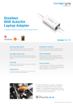
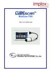
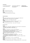
MCube Europe
T-BS-S04
version: 01-2006
Procedure
TROUBLESHOOTING
Goal
User
Indication
- Evaluate problem and solve it
- Sales Representatives / End users
- After questions / complains
Possible actions
- Send in unit for repair / maintenance
Needed items
BioCon-500 Cubescan
Calibration phantom
: BC500-1
: BC5C-0008
Protocol
: L-BS-S03 Procedure calibration check
User’s Manual
: P-BS-P01
Service Manual
: P-BS-S01
Service request form.
: L-BS-03 A
__________________________________________________________________
Table of Contents
Page
1.
2.
3.
4.
5.
6.
7.
8.
9.
10.
11.
12.
System does not start up
System can’t be turned off
Initial screen is not displayed when turning on the system
The green LED is not turned on when the power adapter is connected
No Scan head message is displayed during / before scanning
No Paper message is displayed during printing / no printed image
The system turns off while in use
No image is displayed after scanning
Error in printing (No feeding)
System starts up with white and black squares
Measurements (scanned volumes) are not accurate
Error Messages
A.
B.
C.
D.
E.
F.
G.
H.
How can I change the Time & Date
How can I put in the Hospital Name
How can I change the print options
How can I change thermal paper in the printer
How can I change the brightness of the LCD screen
How can I review all 12 scanning images
How can I only store the last scanned value in stead of highest value
How can I display the scan status
1
2.
2.
2-3.
3.
3.
3-4.
4.
4-5.
5.
5.
5-6.
6.
7.
8.
10.
11.
12.
13.
14.
17.
MCube Europe
T-BS-S04
version: 01-2006
1. System does not start up
Is POWER key pressed for more
1
than 1 second?
2
Measure the voltage of battery
module.
3 Is battery module connected?
The system operates when P-BS-P01 Users manual
pressing the POWER key P-BS-P02 Users protocol
for more than 1 second.
Medical Technical
Departm.
More than +7V
Renew Battery
Article: BC5C-0005
P-BS-S01
P. 22
If not connected, connect
Back side main unit
the battery module.
In compartment
2. System can’t be turned off
1
Is POWER key pressed more than
1 second?
Is the system not turned off even
2 when pressing the Power key for
more than 1 second?
The system operates
when pressing POWER
key for more than 1
second.
Turn the power off by
removing the battery
module from the system.
And exchange control
boards.
P-BS-P01 Users manual
P-BS-P02 Users protocol
Medical Technical
Departm.
P-MC-C01 Catalogue
Article: BC5J-0001 ~ 0007
3. Initial screen is not displayed when turning on the system
1
Is the backlight flickering on the
LCD screen ?
The system is to cold.
Should be between
(10 º ~ 40 º C)
2 Is the screen very dark or bright. ?
Adjust the brightness
System starts up with white and
black squares
System is in the
Maintenance Mode
3
4 Is backlight on in LCD?
5
Is the FPC connector to the LCD
module well connected?
Check if the connector
for backlight of LCD is
connected properly.
Check if the connector is
connected properly.
Check the voltage between the
6 Control board ground and 12th pin Check if -22V (+/-1V).
of JP5.
Check the voltage between the
7 Control board ground and 13th pin Check if -21V (+/-1V).
of JP5.
8 Is the system turned off?
Try again after replacing
the LCD module.
2
Wait until the unit has
warmed up. (18 º C)
See point E.
P-BS-P01
P.26
Change system to patient
mode
See procedure L-BS-S03
Medical Technical
Departm.
P-BS-S01
Medical Technical
Departm.
P-BS-S01
Medical Technical
Departm.
P-BS-S01
Medical Technical
Departm.
P-BS-S01
Medical Technical
Departm.
P-BS-S01
MCube Europe
T-BS-S04
9 The system is not turned off.
version: 01-2006
Test again after replacing
the Control board.
Medical Technical
Departm.
P-BS-S01
4. The green LED is not turned on when the power adapter is connected
1
Is green LED not turned on even
when the system is OFF?
Green LED is not turned on when
2 the system (power adapter) is
connected to power
Is the 4 pin connector connecting
3 the Keyboard and Charging board
connected?
4 Green LED is not turned on even
when the system is OFF?
Green LED is on when the system
5 is OFF, but it is turned off when
the system is ON.
Yes ->Refer to item 2.
No -> Refer to item 4
Check if connection of
the charger in rolling cart
or extension cord in the
case is OK
Check the connection
status and if not
connected, connect 4 pin
connector.
Replace charging board.
No problem.
Because of charging
control in Control board
sometime Green LED is
off when system is on.
Medical Technical
Departm.
P-BS-S01
See procedure
P-BS-S03
Rolling cart assembling
Medical Technical
Departm.
P-BS-S01
Medical Technical
Departm.
P-BS-S01
P-BS-P01 Users manual
5. No Scan head message is displayed during / before scanning
Is the ultrasonic probe connected
1
well to the main body?
Is open between the the 3rd and
2
6th pin of the probe connector?
The message is displayed when
3 the 3rd and 6th pin of Probe
connector is short
If not, NO SCANHEAD
message is displayed
when the scan button is
pushed.
Test again after replacing
with other ultrasonic
probe
Request service from the
headquarter
(Re-)Connect
the Scan head / Probe
P-BS-P01 Users manual
Medical Technical
Departm.
P-BS-S01
Medical Technical
Departm.
P-BS-S01
6. No Paper message is displayed during printing / no printed image
1
Does printer module have thermal
paper?
If not, insert thermal
paper.
2
No image printed on the thermal
paper
Check if the right side up
of the thermal paper is
placed in the printer
Paper roll does not fit in the
3 printer
Check dimensions of the
paper roll
3
P-BS-P01 Users manual
Page 27
Turn the paper roll and try
again or adjust Print
Density : Medical
Technical Departm.
P-BS-S01
P-MC-C01 Catalogue
Article:BC5C-0002
MCube Europe
T-BS-S04
4
version: 01-2006
Does message still appears even
when there is paper?
Try again after replacing
the control board.
Medical Technical
Departm.
P-BS-S01
7. The system turns off while in use
Is auto power-off function active
1 (on) in the setup menu of the
Maintenance mode?
Is the system turned off with the
message of “BATTERY LOW,
2
SYSTEM WILL BE TURNED
OFF”?
When auto power-off
function is active, system
will be turned off if no
key input is made during
the fixed time.
Turn off the system to
protect the battery
module if the power is
insufficient. Try again
after charging.
Medical Technical
Departm.
P-BS-S01
If the system turns off after
a few scans and the battery
has been charged: renew
the battery
P-MC-C01 Catalogue
Article:BC5C-0005
8. No image is displayed after scanning
Image
1
Description
In this case, the mode
showing the scan
result is set as
CONTOUR.
Normal Image
Scanned image from
open object(in air)
2
This can be changed into
B-mode image
See : P-BS-S01
Page 41
Make sure that the probe
(dome) is faced
downwards during
scanning in air (as when
you scan a patient)
No bladder volume
(empty bladder 0 ml)
3
Medical Technical
Image ,when the
transducer connection Department.
P-BS-S01
is open.
Check the resistance
from the ultrasonic
probe connector to
the 18th and 20th pin
4
MCube Europe
T-BS-S04
version: 01-2006
Same result:
4
Error in transducer
connection.
Retry after replacing
the probe
Medical Technical
Department.
P-BS-S01
5
Check if ‘SCAN
RESULT’ is set as
‘CONTOUR’.
Yes, retry after
setting as ‘BMODE’.
No, request service
from the headquarter.
Changing into B-mode
image
See : P-BS-S01
Page 42
Same result:
Medical Technical
Department.
P-BS-S01
9. Error in printing (No feeding)
P-BS-P01
Users manual
Page 27
1
Thermal Paper
No paper.
Properly inserted.
2
Motor sound?
Yes, go to 1
No, check the printer
connector
P-BS-P01
Users manual
Page 27
Not solved?
Replace control board
or printer
Medical Technical
Department.
P-BS-S01
3
10. System starts up with white and black squares
System starts up with white and
1
black squares
System is in the
Maintenance Mode
Change system to patient
mode
See procedure L-BS-S03
11. Measurements (scanned volumes) are not accurate
One displayed image (bladder) is
1
not seen on the screen
2
One displayed image (bladder) is
not seen on the screen
3 Scanned volume is different from
catheterized volume
See procedures :
P-BS-P01
Training : T-BS-03
Medical Technical
Check image with
Department.
point 8.
P-BS-S01
Accuracy of the system is See procedures :
± 20 % (0~699 ml)
P-BS-P01
Re-angle the probe or
move the probe away
from the pubic bone
Make sure that the
images on the screen are
correct and that the
bladder is shown in the
centre of the scanning
5
Training : T-BS-03
- P-BS-P02
Users protocol
MCube Europe
T-BS-S04
version: 01-2006
area (targeting circle)
The probe should be
placed 4 cm above the
pubis on the midline
(lower abdomen)
3 Scanned volume is different from
catheterized volume
Apply ultrasonic gel on
probe cap evenly
(no air trapped in Gel)
- P-BS-P03
Protocol for ward
- P-BS-P04
Quick reference
- P-BS-P05 ~ 14
Protocols per ward
- T-BS-07
Learning package
Obese patients:
Probe below belly
The scan button on the
probe should be on the
right side of the patient
The gender should be
selected
Perform a Calibration
Check
(between 121 ~ 139 ml)
result Negative ►
Send unit to Medical
Technical Department for
Calibration
- L-BS-S03
Calibration check
Medical Technical
Department.
P-BS-S01
12. Error Messages
NO DATA AVAILABLE
No measured data or
viewing B-mode image
See point 8.
BATTERY LOW.
RECHAGE BEFORE NEXT USE
Power shortage
SYSTEM WILL BE TURNED OFF
See point 7.
NO PAPER
No printer paper
See point 6 & 9
NO SCANHEAD
No connecting probe
See point 5.
6
MCube Europe
T-BS-S04
version: 01-2006
A. How can I change the Time & Date ( in Standard Mode)
Reference: P-BS-P01 / Users manual / Page 13
To enter the SETUP mode, push UP KEY (red arrow)
a. Move the cursor at Set Date/Time by up or
down key
b. Push the (green arrow) Enter key
c. Move the cursor to the position by left or right
arrow key, push up or down key for selecting
digits.
d. Push the Enter key (green Arrow) after
changing date / time.
e. Move the cursor to Exit by
down arrow key. Push the Enter key (green
Arrow) to exit setup page
7
MCube Europe
T-BS-S04
version: 01-2006
B. How can I put in the Hospital Name (in Advanced Mode only)
Reference: P-BS-P01 / Users manual / Page 16
To put in the hospital name the system should be in the advanced mode
To enter the SETUP mode, push UP KEY (red arrow)
a. Move the cursor to System Mode by up or down key
b. Push the Enter key (inside arrow keys)
c. Push the left or right arrow key to select a desired
mode
- Standard
- Advanced
d. Push the Enter key after changing system mode.
e. Move the cursor to Exit by down arrow key. Push the
Enter key to exit setup page
8
MCube Europe
T-BS-S04
version: 01-2006
To enter the SETUP mode / Advanced, push UP KEY (red arrow)
a. Move the cursor at Hospital Name by up or down key
b. Push the Enter key (inside arrow keys)
c. Move the cursor to a desired position and push the
Enter key.
(e.g. M)
d. After finish input the name, move the cursor to DONE.
Push the Enter key.
e. Move the cursor to Exit by down arrow key. Push the
Enter key to exit setup page.
9
MCube Europe
T-BS-S04
version: 01-2006
C. How can I change the print options (in Standard Mode)
Reference: P-BS-P01 / Users manual / Page 15
To enter the SETUP mode, push UP KEY (red arrow)
a. Move the cursor at Print Option by up or down key
b. Push the Enter key (inside arrow keys)
Fig. 3.17
c. Push the left or right arrow key to select a desired
mode.
- Value Only
- Raw Image
- Walls
- All Planes
.
d. Push the Enter key to finish print option change.
e. Move the cursor to Exit by down arrow key. Push
the Enter key to exit setup page.
10
MCube Europe
T-BS-S04
version: 01-2006
D. How can I change thermal paper in the printer
Reference: P-BS-P01 / Users manual / Page 27
a. Open the printer cover
as the left image.
b. Grab a printer paper in
one hand as the left
image and slightly pull
out the paper to insert in
the paper cart by using
the other hand.
Make
sure
that
the
printable side is facing
the pint head
(see left image)
c. Close the printer cover
after inserting papers in
printer cart.
11
MCube Europe
T-BS-S04
version: 01-2006
E. How can I change the brightness of the LCD screen
Reference: P-BS-P01 / Users manual / Page 26
Regulating the LCD brightness
Press the enter button in the centre (see blue arrow) and at the same time
the arrow button pointed upwards
(=brighter)
or
the arrow button pointed downwards (=darker)
( see red arrows )
Short key functions
Short key
Function
Remark
Enter + →
Turns over another images of 12
images
Displays 2 images
on LCD
Enter + ←
Regulates contrast of images on 4
steps
Rotates 4 steps
Enter + ↑
Regulates LCD brightness to
brighter
Enter + ↓
Regulates LCD brightness to
darker
12
MCube Europe
T-BS-S04
version: 01-2006
F. How can I review all 12 scanning images
Reference: P-BS-P01 / Users manual / Page 26
After having a scan result on the LCD screen (see below)
SCAN result (B-Mode)
Review other images, displayed per 2 images on LCD Screen
Short key functions
Short key
Function
Remark
Enter + →
Turns over another images of 12
images
Displays 2 images
on LCD
Enter + ←
Regulates contrast of images on 4
steps
Rotates 4 steps
13
MCube Europe
T-BS-S04
version: 01-2006
G. 1. How can I only store the last scanned value in stead of highest value
(see also G. 2. below)
(in Advanced Mode only)
ON
1. Stores the maximum SCAN RESULT of one session in Flash memory
OFF
2.
SCAN RESULT will not be deleted if the power is put off and back on
1.
Flash memory does not store any data
To enter the SETUP mode / Advanced, push UP KEY (red arrow)
a. Move the cursor at Flash Store by up or down key
b. Push the Enter key (inside arrow keys)
c. Move the cursor by left or right key to on or off and
push the Enter key.
d. Move the cursor to Exit by down arrow key. Push
the Enter key to exit setup page.
14
MCube Europe
T-BS-S04
version: 01-2006
G. 2. How can I only store the last scanned value in stead of highest value
(in Maintenance Mode only)
* For this input ask your Medical Technical Department
Maintenance Mode
Maintenance mode can be used to adjust the system variables. Set-up of those variables
follows the procedure below.
Check ID OK!!!
1
Erase Sector OK!!!
To enter the Maintenance mode, push LEFT key
Blank Check OK!!!
with ENTER key being pushed and then push
Program OK!!!
PRINT key after the system is turned on and the
Verify OK!!!
initial screen is displayed. At this time, the
Programming is completed!!!
information as left is displayed on the screen.
Turn off the system and again turn it on to have the
2
checkers as shown left on LCD.
<<MAINTENANCE MODE>>
The initial screen of the system is displayed after
approximately 10 seconds of the appearance of
Maintenance mode should be
accessed by only qualified person.
3
1. To go to maintenance mode
press ENTER key.
2. To return top menu
checkers. At this time, push RIGHT key with LEFT
key being pushed together to display the screen as
left.
Push ENTER key to display maintenance setup
menu, DOWN key to return to the previous page.
press DOWN key.
15
MCube Europe
T-BS-S04
version: 01-2006
▶ Calibrat.(M2)
4
Push ENTER key from the screen 3 above to
Return
display maintenance set-up menu as left.
Min. Contrast
2
Max. Contrast
8
Store Mode
Current
Auto Power
5 minutes
Use up/down key to move menu items from the
Print Density
8
menu.
Scan Status
on
*) Key manipulation
▶ appears beside the current menu item. To replace
Exit
the item value, push ENTER key while the ▶ is still
displayed for the corresponding item. To change the
item value, scroll until the desired value appears by
using left/right value and push ENTER key.
*) Refer to the table below for the details.
When the set-up is done, push LEFT key with
ENTER key being pushed and then push LEFT key
5
Check ID OK!!!
to display the initial screen without having the
Erase Sector OK!!!
checkers
Blank Check OK!!!
information as left is displayed on the screen. And
Program OK!!!
then turn the system off.
during rebooting. At this
time, the
Verify OK!!!
Programming is completed!!!
Appoints which one to store from the current session. In case of current, the last
Store Mode
scanned value is stored. And in case of maximum, the image data with
maximum volume is stored.
Inapplicable at present but an upgrade is scheduled in the near future.
16
MCube Europe
T-BS-S04
version: 01-2006
H. How can I display the scan status (in Maintenance Mode only)
* For this input ask your Medical Technical Department
Maintenance Mode
Maintenance mode can be used to adjust the system variables. Set-up of those variables
follows the procedure below.
Check ID OK!!!
1
Erase Sector OK!!!
To enter the Maintenance mode, push LEFT key
Blank Check OK!!!
with ENTER key being pushed and then push
Program OK!!!
PRINT key after the system is turned on and the
Verify OK!!!
initial screen is displayed. At this time, the
Programming is completed!!!
information as left is displayed on the screen.
Turn off the system and again turn it on to have the
checkers as shown left on LCD.
2
<<MAINTENANCE MODE>>
The initial screen of the system is displayed after
approximately 10 seconds of the appearance of
Maintenance mode should be
accessed by only qualified person.
3
1. To go to maintenance mode
press ENTER key.
2. To return top menu
checkers. At this time, push RIGHT key with LEFT
key being pushed together to display the screen as
left.
Push ENTER key to display maintenance setup
menu, DOWN key to return to the previous page.
press DOWN key.
17
MCube Europe
T-BS-S04
version: 01-2006
▶ Calibrat.(M2)
4
Return
Min. Contrast
2
Max. Contrast
8
Push ENTER key from the screen 3 above to
display maintenance set-up menu as left.
Store Mode
Current
*) Key manipulation
Auto Power
5 minutes
Use up/down key to move menu items from the
Print Density
8
menu.
Scan Status
on
▶ appears beside the current menu item. To replace
Exit
the item value, push ENTER key while the ▶ is still
displayed for the corresponding item. To change the
item value, scroll until the desired value appears by
using left/right value and push ENTER key.
*) Refer to the table below for the details.
When the set-up is done, push LEFT key with
ENTER key being pushed and then push LEFT key
5
Check ID OK!!!
to display the initial screen without having the
Erase Sector OK!!!
checkers
Blank Check OK!!!
information as left is displayed on the screen. And
Program OK!!!
then turn the system off.
during rebooting. At this
time, the
Verify OK!!!
Programming is completed!!!
Scan Status
On/off control scan status information which shows how much current scan is
centered.
18