1
SERVICE PROCEDURES REQUIRING MINOR DISASSEMBLY
SERVICE MANUAL NUMBER 14
11. If roller or plunger pin is not centered:
a. Ensure adjustable stud is at bottom of slot in shift lever.
b. Check remote control for proper shift cable output [3 in. (76 mm) ± 1/8 in. (3 mm)].
Refer to “Installation Requirements.”
c. If a and b are correct, ensure drive unit shift cable is not crushed or kinked. (If drive
unit shift cable is binding, the shift cutout switch roller or plunger pin will move off
center when shifting “into” and “out of” forward and reverse).
NOTE: If shift cable was damaged during installation, install new shift cable assembly in
accordance with instructions contained in sterndrive service manual, then repeat shift cable
adjustment procedure.
NOTE: Some controllers, such as the Commander 3000, have different adjustment procedures. Refer to the appropriate installation instructions for the model being repaired..
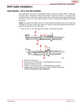
12. After remote control shift cable has been properly adjusted, reinstall cable and shift
assist assembly (if applicable) and secure with hardware as shown. If shift assist
assembly attaching points will not align, push in or pull out on end of shift assist
assembly to install. Do not attempt to readjust shift cable.
d
e
a
f
b
g
c
50308
With Shift Assist Assembly
a - Remote Control Shift Cable
b - Shift Assist Assembly
c - Clevis Pin
d - Cotter Pin (Spread Both Prongs)
e - Large I.D. Washer
f - Small I.D. Washer
g - Locknut (Tighten Until Bottomed, Then Back Off 1/2 Turn)
90-818177--3 APRIL 2001
Page 4A-35