1
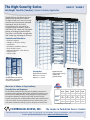
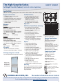
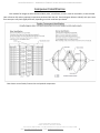
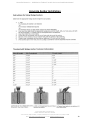
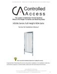
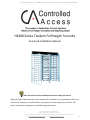
Controlled Access Inc. - HS400 Series Tandem Turnstile Service and Installation Manual
HS400 Series Tandem Full Height Turnstile
Service & Installation Manual
Note: Successful turnstile installation depends on reading this manual.
Important Note: Please keep this service manual after installation. If an installation is done by a
construction company or outside installer, please pass this book along to the end user. This
book is required for maintenance, troubleshooting, and repairs.
Security Begins With Controlled Access
1636 W. 130th Street, Brunswick, OH 44212
Toll Free Phone: (800) 942-0829 | Fax: (800) 942-0828 / Phone: (330) 273-6185 | Fax: (330) 273-4468
Web: http://www.controlledaccess.com | E-mail: [email protected]
1
Controlled Access Inc. - HS400 Series Tandem Turnstile Service and Installation Manual
Table of Contents
HS400 Tandem Full Height Data Sheets
3
Tandem Component Identification
5
Fastener List
6
Pre-installation Tips
7
Concrete Pad Sizes
9
Concrete Anchor Installation Instructions
10
Turnstile Installation
11
6500 Series Control Head Information
16
6500 Series Full Height Control Head Parts Breakdown
17
6500 Series Full Height Control Head Parts List
18
6500 Series Control Head Configuration Information
19
6500 Series Control Head Locking Bar Information
20
6500 Series Control Head Dowel Pin Placement
21
6500 Series Control Head Shock Adjustment
22
6500 Series Full Height Control Head Electrical Information
23
6500 Series Full Height Control Head Limit Switch Information
29
6500 Series Control Head and Turnstile Maintenance & Cleaning
31
6500 Series Control Head Testing
32
6500 Series Control Head Troubleshooting
33
Proper Turnstile Usage
35
Warranty Information
36
Appendix: Component Spec Sheets & Custom Documents
Security Begins With Controlled Access
1636 W. 130th Street, Brunswick, OH 44212
Toll Free Phone: (800) 942-0829 | Fax: (800) 942-0828 / Phone: (330) 273-6185 | Fax: (330) 273-4468
Web: http://www.controlledaccess.com | E-mail: [email protected]
2
The High-Security Series
HS427-T | HS430-T
Full-Height Turnstile (Tandem) | Interior & Exterior Application
Controlled Access manufactures the most
reliable full-height turnstiles available.
The High-Security Series units can be engineered to meet all your security and control
requirements, and can be created
as stand-alone units, or as part of an
integrated system. Available in stainless
steel (304 or 316), carbon steel with powder
coating, or hot-dipped galvanized finish.
These units can be fitted for any application
with leading edge technology and features.
Controls and Interfaces
• Biometric Integration
• Fail-Open or Fail-Secure Locking
• Card Readers
• Push-Button and Wireless Remotes
• Electronic/LCD Counters
• Manual Key Override – both directions
• Metal Detection
• Indicator Lights
Size Options
(pedestrian clearance):
Hot-dipped Galvanized finish
Also available in stainless steel
or power coated finishes.
HS427-T: 27” (686mm)
HS430-T: 30” (782mm)
We’re the #1 Choice of Top Architects,
Security Pros and Engineers
Built in the USA
For two decades, Controlled Access has been the globally trusted name in
pedestrian control equipment. Made in Ohio and shipped worldwide, we are
the first choice of leading architects, facility managers, security consultants
and engineers. Whether your project requires high security full-height
turnstiles, waist-high units, or matching ADA accessible gates, Controlled Access
is the secure choice. And, we’re experienced in access control systems, from
card readers to biometric scanning, to give you the power to control access.
CONTROLLED ACCESS, INC.
Optional black or
safety orange end caps
available for
galvanized units.
PassagePassageOverall
Depth Width Width HeightHeight
A*B*C*D*E*
HS427-T
57”
94”
27”
84”
91”
1448mm 2388mm 686mm 2134mm 2311mm
HS430-T
91”
59.1”
102”
30”
84”
1501mm 2591mm 762mm 2134mm 2311mm
* See CAD drawings on reverse side.
The Leader in Pedestrian Access Control
1636 West 130th Street | Brunswick, Ohio 44212 | Ph: 330.273.6185 | Fax: 330.273.4468 | Toll-Free Ph: 800.942.0829 | Toll-Free Fax: 800.942.0828
E-mail: [email protected] | www.controlledaccess.com
0114
The High-Security Series
HS427-T | HS430-T
Full-Height Turnstile (Tandem) | Interior & Exterior Application
Applications:
Ideal for controlling orderly flow of foot traffic in both indoor and outdoor settings
Design & Construction:
Available Finishes:
• Designed for secure operation with
aesthetics in mind
• Featuring fully welded exterior components
• Minimal exposed stainless steel hardware
• Heavy gauge materials meeting ASTM standards
• Hot dipped galvanized carbon steel
• Carbon steel with powder coating
(standard color is black/other colors available upon request)
Measures:
HS427-T
Operation:
6500 Series Control Head, featuring:
Size of opening (pedestrian clearance) HS427-T 27” (686mm)
Arm and Barrier Tubing Sizes
1 1/2” diameter 14 gauge (38mm) - Standard
1 3/4” diameter 14 gauge (44mm) - Optional
WidthDepth
94” (2388mm)
57” (1448mm)
HS430-T
Size of opening (pedestrian clearance) HS430-T 30” (762mm)
Arm and Barrier Tubing Sizes
1 1/2” diameter 14 gauge (38mm) - Standard
1 3/4” diameter 14 gauge (44mm) - Optional
WidthDepth
102” (2591mm)
59.1” (1501mm)
All models:
• Overall exterior height 91” (2311mm)
• Pedestrian walk through height 84” (2134mm)
Matching Swing Gate available
(see model HS336 Manual Passage Gate information)
HS336 - Back
(stainless steel
with optional
mesh push bar)
• Our signature 304 stainless steel,
No. 4 satin finish, or 316 stainless
• Auto-indexing (self-centering) with
adjustable hydraulic shock suppression
• Hardened tool steel locking bars, cam and roller assemblies
• Permanently lubricated bearings
• Your choice of manual or electronic
control on both directions
• Nearly universal integration to any number
of access control systems
• Your choice on each electronic direction
of locking or unlocking on power failure
Options:
• Card reader mounting plates
• Daylight visible indicator lights
• Bi-directional key overrides
• Lockout bar (padlock not included)
• Decorative arm caps (for galvanized unit)
• Stainless steel overhead full canopy
• Half canopy (covers passageway)
• 8 digit key resettable LCD counter
with seven year lithium battery
• Cold weather package, including thermostat
controlled heater and insulated mainframe
• Metal detection
• Push button and wireless remotes
• Heel guard arm covers
• Hinged or split covers
(for tight clearance installations)
• Additional options available upon request
Warranty:
Units are warranted against defects in materials
and workmanship for a period of one year from
date of delivery. See warranty information for specific details.
CONTROLLED ACCESS, INC.
Dimensions are approximate.
Electrical Specifications:
(per rotor)
Input Voltage: 100-240 VAC
Input Current: 1.3 - .55 A
Frequency: 50/60 Hz
Storage Temperature: -4 to 158˚F
Operating Temperature: 32 to 122˚F
(Cold weather package available)
Operating Voltage: 24VDC
Operating Current: 1.2 A (typical)
Standards and Codes:
Austenitic stainless steel:
ASTM A240, A249, A276
Hot rolled steel:
AISI C-1020, AISI C-1018
Hot dipped galvanizing:
ASTM A-143, ASTM A-153-80
Stainless steel fasteners:
ASTM A-320
American Welding Society (AWS)
Standard D 1.1
The 6500 series control head is
certified to conform to UL Standard
325 & UL Subject 2593
Controlled Access, Inc. is
a registered ISO 9001:2008
company
The Leader in Pedestrian Access Control
1636 West 130th Street | Brunswick, Ohio 44212 | Ph: 330.273.6185 | Fax: 330.273.4468 | Toll-Free Ph: 800.942.0829 | Toll-Free Fax: 800.942.0828
E-mail: [email protected] | www.controlledaccess.com
0114
Controlled Access Inc. - HS400 Series Tandem Turnstile Service and Installation Manual
Component Identification
Each tandem full height turnstile should include 4 yokes, a mainframe, 2 rotors, 2 barrier assemblies, 2 control heads
(with a fastener kit) and any optional components purchased with the unit. See the diagram below to identify each part. Note
that some parts may look slightly different, depending on which model was purchased.
*Not shown: control heads, fastener kits and optional components.
Security Begins With Controlled Access
1636 W. 130th Street, Brunswick, OH 44212
Toll Free Phone: (800) 942-0829 | Fax: (800) 942-0828 / Phone: (330) 273-6185 | Fax: (330) 273-4468
Web: http://www.controlledaccess.com | E-mail: [email protected]
5
Controlled Access Inc. - HS400 Series Tandem Turnstile Service and Installation Manual
Tandem Fastener List
QTY 8 -
3/8 X 1 ½ CARRIAGE BOLTS W/ NUTS, WASHERS &
LOCK WASHERS: CONTROL HEAD TO MAIN FRAME
QTY 8 -
3/8 X 1 ½ CARRIAGE BOLTS W/ NUTS: YOKE TO BOX
TUBING
QTY 4 -
3/8 X 1 ½ CARRIAGE BOTS W/ NUTS, WASHERS
& LOCK WASHERS: BARRIER TO BOX TUBING
QTY 4 -
3/8 X 3 CARRIAGE BOLTS W/ NUTS, WASHERS & LOCK
WASHERS: BARRIER TO BOX TUBING
QTY 12 - 3/8 X 3 CARRIAGE BOLTS W/ NUTS, WASHERS & LOCK
WASHERS: BOX TUBING TO MAIN FRAME
QTY 16 - 3/8 X 4 WEDGE TYPE ANCHORS W/ NUTS & WASHERS: YOKES
TO CONCRETE
QTY 2 -
5/8 X 4 WEDGE TYPE ANCHOR W/ NUTS, BEARING BLOCK &
BEARING: CENTER COLUMN MOUNTING
MAKE SURE BEARING IS GREASED
Security Begins With Controlled Access
1636 W. 130th Street, Brunswick, OH 44212
Toll Free Phone: (800) 942-0829 | Fax: (800) 942-0828 / Phone: (330) 273-6185 | Fax: (330) 273-4468
Web: http://www.controlledaccess.com | E-mail: [email protected]
6
Controlled Access Inc. - HS400 Series Tandem Turnstile Service and Installation Manual
Pre-installation Tips
When installing a new turnstile, there are several helpful hints that can be used in order to make
the installation go smoothly. It is highly recommended that these are reviewed before installation.
•
•
If pouring a new concrete pad, make certain it is level. If the turnstile is not level, it may not
operate correctly. If installing on an existing concrete pad, shim the turnstile so it is level.
If the turnstile is electronic, pre-plan how it will be wired. We provide several options for
running conduit into each turnstile.
o The end plates on the main frame have punch outs for conduit.
o
•
•
If purchased with an optional card reader plate, the suggested method for running the
wire is through the yokes, into the cross arms and into the main channel. Use a shielded
2 conductor 22 gauge cable per direction.
Electronic turnstiles are operated from a provided 24VDC 2.1 amp power supply. Installing
outlet receptacles inside of the main channel through provided conduit access is required.
Access control devices, such as card readers, push buttons, biometric devices, etc. need to
operate on a normally open dry momentary contact of one second or less. If your access
control device is unable to provide a contact of one second or less, you can enable an on-board
one shot timer (see later in guide).
Security Begins With Controlled Access
1636 W. 130th Street, Brunswick, OH 44212
Toll Free Phone: (800) 942-0829 | Fax: (800) 942-0828 / Phone: (330) 273-6185 | Fax: (330) 273-4468
Web: http://www.controlledaccess.com | E-mail: [email protected]
7
Controlled Access Inc. - HS400 Series Tandem Turnstile Service and Installation Manual
When installing a turnstile purchased with card reader plates, pay special attention when working
with the curved yoke pieces. One side of the yoke will be drilled specially for card reader plate
mounting.
Card reader plates are mounted
on the strap across the center of
the yokes on the outside of the
turnstile
•
Proper rotor alignment (left) is important for turnstile operation. Improper rotor alignment
(right) can lead to users becoming trapped inside of the turnstile.
•
Tools required for installation:
o Hammer drill
o 3/8 concrete bit
o 5/8 concrete bit
o Hammer
o Punch
o Marker
o Plumb-bob
o 9/16 wrench
o 15/16 wrench
o 1/8 allen wrench
o Level
o Grease gun
o Safety gloves
o Safety glasses
Security Begins With Controlled Access
1636 W. 130th Street, Brunswick, OH 44212
Toll Free Phone: (800) 942-0829 | Fax: (800) 942-0828 / Phone: (330) 273-6185 | Fax: (330) 273-4468
Web: http://www.controlledaccess.com | E-mail: [email protected]
8
Controlled Access Inc. - HS400 Series Tandem Turnstile Service and Installation Manual
Concrete Pad Sizes
Security Begins With Controlled Access
1636 W. 130th Street, Brunswick, OH 44212
Toll Free Phone: (800) 942-0829 | Fax: (800) 942-0828 / Phone: (330) 273-6185 | Fax: (330) 273-4468
Web: http://www.controlledaccess.com | E-mail: [email protected]
9
Controlled Access Inc. - HS400 Series Tandem Turnstile Service and Installation Manual
Concrete Anchor Installation
Security Begins With Controlled Access
1636 W. 130th Street, Brunswick, OH 44212
Toll Free Phone: (800) 942-0829 | Fax: (800) 942-0828 / Phone: (330) 273-6185 | Fax: (330) 273-4468
Web: http://www.controlledaccess.com | E-mail: [email protected]
10
Controlled Access Inc. - HS400 Series Tandem Turnstile Service and Installation Manual
Turnstile Installation
Step 1) If needed, pour a level concrete pad at least 4” thick at the schematic on page 9.
Note: A level surface is required for proper turnstile operation.
Step 2) Unpack turnstile(s) and verify all parts are included. Use the parts checklist in the beginning of
this book.
Step 3) Unwrap the main channel (Figure A) from cardboard and foam packaging. Remove (6) 10/24
button head screws and take the lid off.
Figure A: Main channel
Step 4) Remove cross arms from the main channel. Using a square, assemble cross arms to the
underside of the main channel by using the provided 3” carriage bolts as shown below (Figure B).
Figure B: Assembled mainframe
Note: Carriage bolts are designed to be hammered into place, so on locations where the hole
is round, simply tap the head of the bolt into the hole.
Security Begins With Controlled Access
1636 W. 130th Street, Brunswick, OH 44212
Toll Free Phone: (800) 942-0829 | Fax: (800) 942-0828 / Phone: (330) 273-6185 | Fax: (330) 273-4468
Web: http://www.controlledaccess.com | E-mail: [email protected]
11
Controlled Access Inc. - HS400 Series Tandem Turnstile Service and Installation Manual
Step 5) Utilizing the assembled mainframe, mark holes for the 3/8” concrete anchors to circled holes
pointed out below (Figure C)
Figure C: Using mainframe as a template to mark holes for concrete anchors (circled dots)
Step 6) Before drilling, verify the cross arms were square to the mainframe by temporarily setting a yoke
and a barrier over each set of holes to ensure that the hole patterns match. (Figure D).
Figure D: Location of the barriers and yokes.
Security Begins With Controlled Access
1636 W. 130th Street, Brunswick, OH 44212
Toll Free Phone: (800) 942-0829 | Fax: (800) 942-0828 / Phone: (330) 273-6185 | Fax: (330) 273-4468
Web: http://www.controlledaccess.com | E-mail: [email protected]
12
Controlled Access Inc. - HS400 Series Tandem Turnstile Service and Installation Manual
Step 7) Once satisfied with alignment, begin drilling the holes marked with a 3/8 concrete bit. Install
anchors according to concrete anchor installation guide on page 10.
Step 8) Bolt curved yokes into the concrete (Figure E)
Figure E: Mounting the curved yoke pieces to the concrete.
Note: Depending on how the turnstile was ordered, yokes may have two tapped holes with
button head screws on one end of the support strap (in the middle of the yoke) for mounting card
reader plates. These holes should be oriented to the outside of the turnstile.
Step 9) Before continuing, identify the different rotors and barriers based on the component
identification section of this manual (page 5). Once identified, mount the stationary barriers to the
concrete (Figure F)
Figure F: Mounting the stationary barriers to concrete.
Security Begins With Controlled Access
1636 W. 130th Street, Brunswick, OH 44212
Toll Free Phone: (800) 942-0829 | Fax: (800) 942-0828 / Phone: (330) 273-6185 | Fax: (330) 273-4468
Web: http://www.controlledaccess.com | E-mail: [email protected]
13
Controlled Access Inc. - HS400 Series Tandem Turnstile Service and Installation Manual
Step 11) Mount the mainframe on top of yokes and stationary barriers using 1 1/2” carriage bolts
(Figure G).
Figure G: Mounting the mainframe on top of the yokes and barrier.
Step 12) Check the levelness of turnstile. If necessary, shim from the floor to make turnstile level.
Step 13) Using a plumb-bob, mark the holes for the bearings and rotors (Figure H).
Note: This step requires as much precision as possible, or the turnstile may not operate
correctly. Do NOT rely on the mainframe as a template for this hole.
Figure H: Using a plumb-bob to mark holes for rotor placement.
Security Begins With Controlled Access
1636 W. 130th Street, Brunswick, OH 44212
Toll Free Phone: (800) 942-0829 | Fax: (800) 942-0828 / Phone: (330) 273-6185 | Fax: (330) 273-4468
Web: http://www.controlledaccess.com | E-mail: [email protected]
14
Controlled Access Inc. - HS400 Series Tandem Turnstile Service and Installation Manual
Step 14) Drill holes for the 5/8” concrete anchors that hold the bearing blocks (Figure I) and bearings in
place. Install the anchors in the concrete. Install bearing blocks to concrete and add bearings.
Figure I: The bearing blocks used to support the bearings and rotors.
Step 15) Place the rotors on top of the bearing blocks. Make sure that one set of arms on the rotor
points in between the two yoke assemblies (Figure J).
Note: Improper rotor alignment will cause users to become trapped inside of the turnstile.
Figure J: Proper rotor alignment (left) vs. improper rotor alignment (right).
Step 17) Slide the control heads into the tops of the rotors. The control heads have 7/8” hex shafts that
insert into adaptors on the rotors. If the turnstile is electronic, mount the control heads with the power
supplies towards the side of the turnstile that power is ran to. The control heads will function the same
whichever way it is installed into the rotor, but each head might be configured differently.
Step 18) Bolt the control heads to the mainframe using the 1 ½” carriage bolts.
Security Begins With Controlled Access
1636 W. 130th Street, Brunswick, OH 44212
Toll Free Phone: (800) 942-0829 | Fax: (800) 942-0828 / Phone: (330) 273-6185 | Fax: (330) 273-4468
Web: http://www.controlledaccess.com | E-mail: [email protected]
15
Controlled Access Inc. - HS400 Series Tandem Turnstile Service and Installation Manual
6500 Series Control Head Information
All of our turnstiles and ADA gates operate with a mechanism called the 6500 series control
head. This sturdy and easy to maintain drive for the turnstile has replaced all previous model control
heads. It is adaptable to any existing turnstile and comes with each new turnstile purchase. This control
head can be configured in multiple ways to accommodate the security requirements of each individual
job site.
An internal view of an electronically controlled two-way 6500 series control head.
While the head can be configured for mechanical (no electronics) operation, the turnstile’s
security potential is reached in the case of an electronic two way control head. In this instance, each
rotational direction is independently unlocked. Configured properly, this control head will allow for one
rotation per valid entry request. Our anti-backup cams are designed so that it is impossible to become
trapped within the turnstile when properly installed.
Each control head comes pre-configured to your specific needs based off of a directional sheet
that is filled out before shipment. The heads are delivered pre-wired, tested, and adjusted to our factory
recommendations. Installation is simple: connect inputs from access control devices into the logic
controller and plug the unit’s power supply into a 110-240VAC receptacle. The power supply will
automatically set itself to function on your local voltage and convert it to 24VDC.
Note: Proper turnstile operation requires a dry, normally open momentary contact closure (of
one second or less).
Security Begins With Controlled Access
1636 W. 130th Street, Brunswick, OH 44212
Toll Free Phone: (800) 942-0829 | Fax: (800) 942-0828 / Phone: (330) 273-6185 | Fax: (330) 273-4468
Web: http://www.controlledaccess.com | E-mail: [email protected]
16
Controlled Access Inc. - HS400 Series Tandem Turnstile Service and Installation Manual
6500 Series Control Head Configuration Information
The 6500 series can be configured in a number of different ways. All turnstiles operating with the 6500
series control head self center and hydraulically shock to the home position to prevent damage or injury.
Manual both ways: Turnstile rotates freely in both directions. This unsecure configuration is used as a means
to direct traffic through one area. Full height turnstiles can be purchased with a lockout bar which would allow
end user to lock the turnstile with a standard pad lock.
Manual one way: Turnstile rotates in one direction but not the other. This configuration is great for an exit
way.
Electronic one way with free exit: Turnstile rotates freely in one direction and requires access credentials for
the other. This configuration is suitable for secure entry and unsecure exit.
Electronic one way with no exit: Turnstile requires access credentials for one direction and allows no passage
in the other. This configuration is suitable for a secured entryway with an alternate means of exit.
Electronic two way: Turnstile requires access credentials for both directions. This configuration is perfect for
locations requiring secured entry and exit passage.
Fail lock: Upon power failure, turnstile will remain locked in one or both directions. This is convertible to fail
open by ordering an alternate linkage. This can also be known as fail secure.
Fail open: Upon power failure, turnstile will remain unlocked in one or both directions. This is convertible to
fail lock by ordering an alternate linkage. This can also be known as fail safe.
Key override: This option is for a location that the security requirements may change. The key override option
is not intended for everyday use. Should you require an additional lockdown feature on your turnstile, a better
option is a lockout bar (Figure L) with a standard pad lock.
Figure L: Optional lockout bar
Security Begins With Controlled Access
1636 W. 130th Street, Brunswick, OH 44212
Toll Free Phone: (800) 942-0829 | Fax: (800) 942-0828 / Phone: (330) 273-6185 | Fax: (330) 273-4468
Web: http://www.controlledaccess.com | E-mail: [email protected]
19
Controlled Access Inc. - HS400 Series Tandem Turnstile Service and Installation Manual
6500 Series Control Head Locking Bar Information
Any number of configurations is possible on the 6500 series control head. In the case of an electronic
two way head, two independent locking mechanisms are in place. The following diagram indicates which
direction unlocks from which locking mechanism. A logic controller or key override is needed to unlock the
control head in each direction it is configured to lock in.
If removing the locking bar becomes necessary for any reason, two methods can be used. The easiest
method is to punch the ½” dowel pin out from the bottom side of the control head. This releases the locking
bar from the casting. An alternate approach would be to remove the (4) ¼-20 socket head cap screws from the
casting and remove the lid.
When installing or replacing the locking bars into the control head, be sure to take special care to align
the solenoid spring (shown below) or it will not pivot properly.
Security Begins With Controlled Access
1636 W. 130th Street, Brunswick, OH 44212
Toll Free Phone: (800) 942-0829 | Fax: (800) 942-0828 / Phone: (330) 273-6185 | Fax: (330) 273-4468
Web: http://www.controlledaccess.com | E-mail: [email protected]
20
Controlled Access Inc. - HS400 Series Tandem Turnstile Service and Installation Manual
Power Failure State Configuration (Fail Lock / Fail Open)
Each direction on a control head can be independently configured to open or lock upon power failure.
The fail status configuration is based on the pivot point used on the locking bar as well as the linkage and
solenoid spring used. Control heads are preconfigured in our factory before shipment based on a direction
sheet filled out by the end user. In the event a fail status field change is needed, a different linkage and spring
will be required (the part numbers are noted in a table below). Control heads can also be returned to the
factory for reconfiguration for a fee of parts plus approximately 1 hour of labor if desired.
Description
Fail lock linkage
Fail open linkage
Fail open solenoid spring
Fail lock solenoid spring
Part Number
6518
6519
6510
6016
Note: As a reference, it may be important to know that some vendors use different terms
for fail status. Fail open is also known as fail safe, while fail lock is also known as fail secure.
Security Begins With Controlled Access
1636 W. 130th Street, Brunswick, OH 44212
Toll Free Phone: (800) 942-0829 | Fax: (800) 942-0828 / Phone: (330) 273-6185 | Fax: (330) 273-4468
Web: http://www.controlledaccess.com | E-mail: [email protected]
21
Controlled Access Inc. - HS400 Series Tandem Turnstile Service and Installation Manual
6500 Series Control Head Shock Adjustment and Replacement
Our turnstiles come with hydraulic shocks in order to alleviate wear on the control head. These shocks
allow the turnstile to return to the center position without slamming into place. Although we adjust these in
the factory, different environments may require additional field adjustment.
The shock is located adjacent to the index pin. To adjust the shock, loosen the set screw pointed
upwards and adjust the dial. The set screw points at the current setting. A lower number yields more shock,
whereas a higher number yields less shock. The table below indicates approximate shock settings for each
type of product. Individual installations may vary.
Product
Full Height
Waist High
ADA Gate
Approximate Shock Setting
0-2
5-6
4-5
Should the shock need replaced, be sure not to fully thread the shock into the shock housing. Instead,
thread the shock until it no longer spins, and then back the shock out approximately 1 ½ - 2 turns until the set
screw is facing up. Lock down the shock with the provided nut, and then make field adjustments to the shock
strength.
Some larger model turnstiles use an alternate, heavier shock. They adjust in the exact same fashion,
but instead of being held in place with a nut, a ¼-20 set screw is used in the shock housing.
Security Begins With Controlled Access
1636 W. 130th Street, Brunswick, OH 44212
Toll Free Phone: (800) 942-0829 | Fax: (800) 942-0828 / Phone: (330) 273-6185 | Fax: (330) 273-4468
Web: http://www.controlledaccess.com | E-mail: [email protected]
22
Controlled Access Inc. - HS400 Series Tandem Turnstile Service and Installation Manual
6500 Series Control Head Electrical Information
Each electronic control head comes with a power supply, a programmable logic controller (PLC), limit
switches (or proximity sensors) and solenoids. For safety purposes, it is recommended that you read all
literature on the electrical components before attempting to install the control head into a turnstile.
Note: Access control devices need to provide a momentary, normally open dry contact of one
second or less. A longer signal can cause more than one person to be able to pass through the turnstile. If
you are unable to provide a contact of one second or less, an onboard signal converter will automatically
change the signal length to .1 seconds. However, the ability to hold the relay open is lost while that feature
is active.
Security Begins With Controlled Access
1636 W. 130th Street, Brunswick, OH 44212
Toll Free Phone: (800) 942-0829 | Fax: (800) 942-0828 / Phone: (330) 273-6185 | Fax: (330) 273-4468
Web: http://www.controlledaccess.com | E-mail: [email protected]
23
6500 Series Control Head Wiring Legend
Since each control head comes pre-wired, only access control and fire alarm should need to be connected to the
board. If you are unable to fit wires for access control on the 24VDC+ input on the board, the voltage can be
picked up directly from the power supply or from the relay commons (C3 & C4) on the board (C4 may not have
voltage depending on options purchased. There will be a red jumper to C4 if there is). You may also run a jumper
from 24VDC+ to any unused input to give additional contacts if needed.
Note: Directional status outputs are unaffected by optional key overrides as the override occurs
outside of the logic controller.
Security Begins With Controlled Access
1636 W. 130th Street, Brunswick, OH 44212
Toll Free Phone: (800) 942-0829 | Fax: (800) 942-0828 / Phone: (330) 273-6185 | Fax: (330) 273-4468
Web: http://www.controlledaccess.com | E-mail: [email protected]
Controlled Access Inc. - HS400 Series Tandem Turnstile Service and Installation Manual
Overview of the Access Window
On the logic controller, an access window is available to change and adjust many different values. Each value is
referred to as a “device”. The window comprises of 3 primary areas: The device selector window, operation
keys, and the main display window.
Although the logic controller is capable of many functions, all of the devices that the control head operates from
are accessed in “Device Mode”. When device mode is active, the display screen will show DM in the top left
corner.
That being said, it is possible to stray from the device mode settings. In the selected device type section of the
access window, DM, TM, T/C, CTC, TRM, and RLY are all possible selections to load. Again, we are only using DM
(device mode) with the 6500 series control head.
Should you find that you accidently have loaded any other selected device type, simply press
you have once again loaded the DM type.
to scroll until
Security Begins With Controlled Access
1636 W. 130th Street, Brunswick, OH 44212
Toll Free Phone: (800) 942-0829 | Fax: (800) 942-0828 / Phone: (330) 273-6185 | Fax: (330) 273-4468
Web: http://www.controlledaccess.com | E-mail: [email protected]
26
Controlled Access Inc. - HS400 Series Tandem Turnstile Service and Installation Manual
In addition to the device mode window, system mode can be accessed as well.
Although under normal circumstances you should never encounter this window, if by accident you should
happen to come across it, simply press the up or down arrow until the window reads “run”. Press and hold the
button for 3 seconds, and the display will return to device mode.
Additionally, should for any reason the display lettering become red instead of green, you will need to access
system mode to run the program in this fashion. Holding the
key while pressing up and down allows you to
change between system mode and device mode. A third mode, which will display TRM on the left side of the
screen, can also be accessed. Cycle through until the appropriate mode is displayed.
Finally, it is possible to lock the keypad. Should you inadvertently do so, press and hold the
arrow key together for 3 seconds to unlock the keypad again.
button and an
Security Begins With Controlled Access
1636 W. 130th Street, Brunswick, OH 44212
Toll Free Phone: (800) 942-0829 | Fax: (800) 942-0828 / Phone: (330) 273-6185 | Fax: (330) 273-4468
Web: http://www.controlledaccess.com | E-mail: [email protected]
27
Controlled Access Inc. - HS400 Series Tandem Turnstile Service and Installation Manual
Device Settings of the 6500 Series Control Head
While working within device mode, two primary values should be considered. On the top of the display, the
selected device is shown. The 6500 series control head settings can be adjusted with devices 0 – 7.
Pressing the up or down arrows allow you to select which device you wish to modify. Pressing and holding the
key for 3 seconds loads the modification window. While modifying, the digits on the window begin to flash.
Pressing
will move the cursor in a digit. Select the correct digit to modify, then use the arrows to change the
value. Once finished, hold the button for 3 seconds and your adjustment will save.
Should a value inputted not fall within the specified range of the device being modified, the value will
automatically adjust to the highest possible value. A description of each device setting is:
•
•
•
•
•
•
•
•
DM0: Timer value for Direction 1. The range of this setting is 1 – 60 seconds. This is how long the
direction will remain open for if a user does not pass through the direction. The default setting is 7
seconds.
DM1: Timer value for Direction 2. The range of this setting is 1 – 60 seconds. This is how long the
direction will remain open for if a user does not pass through the direction. The default setting is 7
seconds.
DM2: Direction 1 fail status. This determines when the solenoid receives power and is preconfigured
based on each individual order. 0 means the direction is fail lock & 1 means the direction is fail open.
This setting is not affected by factory reset.
DM3: Direction 2 fail status. This determines when the solenoid receives power and is preconfigured
based on each individual order. 0 means the direction is fail lock & 1 means the direction is fail open.
This setting is not affected by factory reset.
DM4: Direction 1 one-shot timer: This setting determines whether or not the access control input length
is ignored and converted to a .1 second pulse internally. Enabling this allows the turnstile to ignore
access control from allowing too many users pass through the turnstile. Disabling it allows access control
to hold the direction open. 0 means the one-shot timer is inactive & 1 means the one-shot timer is
active.
DM5: Direction 2 one-shot timer: This setting determines whether or not the access control input length
is ignored and converted to a .1 second pulse internally. Enabling this allows the turnstile to ignore
access control from allowing too many users pass through the turnstile. Disabling it allows access control
to hold the direction open. 0 means the one-shot timer is inactive & 1 means the one-shot timer is
active.
DM6: Direction 1 multi-swipe: This setting allows more than one access control request to be processed
at a time to allow a faster flow of traffic. The range is 1-3. As each access control request is processed,
each rotation subtracts from the total, allowing a constant flow of traffic. Most installations would
benefit from a value of 2, which is the default setting.
DM7: Direction 2 multi-swipe: This setting allows more than one access control request to be processed
at a time to allow a faster flow of traffic. The range is 1-3. As each access control request is processed,
each rotation subtracts from the total, allowing a constant flow of traffic. Most installations would
benefit from a value of 2, which is the default setting.
Security Begins With Controlled Access
1636 W. 130th Street, Brunswick, OH 44212
Toll Free Phone: (800) 942-0829 | Fax: (800) 942-0828 / Phone: (330) 273-6185 | Fax: (330) 273-4468
Web: http://www.controlledaccess.com | E-mail: [email protected]
28
Controlled Access Inc. - HS400 Series Tandem Turnstile Service and Installation Manual
•
•
DM9: Direction 1 Count: Displays how many valid rotations were made in direction 1. This has a max
value of 60,000 and will reset to 0 once that number is reached. This will not count fire alarm, hold open
or key override rotations. This count is for maintenance and repair logging purposes.
DM10: Direction 2 Count: Displays how many valid rotations were made in direction 2. This has a max
value of 60,000 and will reset to 0 once that number is reached. This will not count fire alarm, hold open
or key override rotations. This count is for maintenance and repair logging purposes.
Additionally, scrolling downward past DM0 will allow you access to DM1999, which resets all settings to factory
defaults (except for solenoid fail status settings). Choose any value greater than 0 to perform the factory reset.
Security Begins With Controlled Access
1636 W. 130th Street, Brunswick, OH 44212
Toll Free Phone: (800) 942-0829 | Fax: (800) 942-0828 / Phone: (330) 273-6185 | Fax: (330) 273-4468
Web: http://www.controlledaccess.com | E-mail: [email protected]
29
Controlled Access Inc. - HS400 Series Tandem Turnstile Service and Installation Manual
6500 Series Full Height Control Head Limit Switches
Direction 1 is canceled by limit switch 1 and direction 2 is canceled by limit switch 2. As the unit rotates,
both limit switches are triggered. However, only the limit switch designated for that direction is utilized to relock
the unit. The switch is triggered towards the end of the rotation. Once it is triggered, the locking mechanism
returns to the locked position, but users may still proceed until the home position is reached.
A minor exception to this is in the case of an ADA swing gate. The limit switch is triggered towards the
beginning of the swing, which allows the locking bar to prevent the gate from over swinging. In this instance, the
limit switches are designated backwards from those on a standard turnstile. Refer to the above diagram to
illustrate which is which.
Note: The control head will not operate properly if the limit switches and top cam are not adjusted
properly or altered from factory shipment.
Security Begins With Controlled Access
1636 W. 130th Street, Brunswick, OH 44212
Toll Free Phone: (800) 942-0829 | Fax: (800) 942-0828 / Phone: (330) 273-6185 | Fax: (330) 273-4468
Web: http://www.controlledaccess.com | E-mail: [email protected]
30
Controlled Access Inc. - HS400 Series Tandem Turnstile Service and Installation Manual
6500 Series Control Head & Turnstile Maintenance & Cleaning
To ensure long life on any turnstile, the following maintenance is recommended.
•
•
•
Annual
o If you have a full height turnstile: On the bottom of each rotor, you should find a grease fitting.
Utilize this fitting to re-grease the bearing that the rotor rests on.
o Make sure all nuts are securely fastened on all parts of the turnstile.
o On the control head, remove the index pin and apply white lithium grease. Use 3 in 1 oil on the
index pin roller. The index pin is easily removed from the control head by disconnecting the
springs from it.
Bi-annual
o Remove the lid from the control head. Clean any debris and apply grease to the shock roller
assembly. Use 3 in 1 oil on the shock piston roller.
o Apply 3 in 1 oil to the bronze bushing on the locking bars.
o Inspect control head parts for wear and tear, replace parts as needed.
o Reassemble control head. Using a removable strength (blue) thread sealer (such as Loctite 242
or 243) on the head bolts will help the control head remain sturdy.
Cleaning
o Galvanized turnstiles can be cleaned with soap and water. Galvanized finish may fade in color
over time, but this is normal.
o Powder coated turnstiles should be cleaned with a non-abrasive cleanser such as Formula 409.
Be sure to inspect for chips on the powder coating and touch them up, or the exposed steel may
rust.
o Stainless steel turnstiles should be polished with a stainless steel wax or polish. In harsh
environments, such as facilities near the ocean or within a chemical plant, stainless steel
turnstiles should be waxed with a simple car wax to prevent surface discoloration on an
annual basis. Discoloration and surface rust can be easily removed with a rust penetrating
product, such as P.B. Blaster, along with non-scratching scouring pads.
Control heads can be removed from the turnstile and shipped to the factory at any time for repairs and
maintenance. Please include contact information so we can call to discuss any issues your control head may
have. Please note that any repairs that cost under $500.00 will require a credit card payment.
Note: The recommended time frames are assuming a maximum of 75000 passages per year. Turnstiles
with heavier traffic should be maintained more frequently.
Security Begins With Controlled Access
1636 W. 130th Street, Brunswick, OH 44212
Toll Free Phone: (800) 942-0829 | Fax: (800) 942-0828 / Phone: (330) 273-6185 | Fax: (330) 273-4468
Web: http://www.controlledaccess.com | E-mail: [email protected]
31
Controlled Access Inc. - HS400 Series Tandem Turnstile Service and Installation Manual
6500 Series Control Head Testing
Security Begins With Controlled Access
1636 W. 130th Street, Brunswick, OH 44212
Toll Free Phone: (800) 942-0829 | Fax: (800) 942-0828 / Phone: (330) 273-6185 | Fax: (330) 273-4468
Web: http://www.controlledaccess.com | E-mail: [email protected]
32
Controlled Access Inc. - HS400 Series Tandem Turnstile Service and Installation Manual
6500 Series Control Head Troubleshooting
Symptom
Turnstile does not unlock.
Cause
Power supply is not receiving
input voltage.
Loose wiring from power supply
to logic controller.
Power supply is not producing
voltage.
Logic controller program is not
running. This can be determined
by the color of the lettering on
the logic controller display
screen. If it is red, it is not
running.
Access control device
malfunction.
More than one person can get
through turnstile.
Control head requiring
maintenance.
Access control device output set
too long.
Loose wiring to the logic
controller from limit switches.
Limit switches are broken.
Limit switches are missing the
triangular top cam.
Unable to hold direction open to
allow multiple people to pass
through the turnstile.
One-shot timers are enabled.
Solution
Verify outlet receptacle installed
in mainframe is operating
correctly and that the power
supply is plugged in.
Refer to pages 23-25 for wiring
information.
Check output voltage from
power supply. It should be
24VDC.
Refer to the “Overview of the
Access Window“ section on page
26 and “run” the program.
Disconnect access control from
circuit board. Momentarily jump
directional inputs. If the turnstile
works properly, contact
manufacturer of access control
device.
Refer to page 31.
This can be avoided by enabling
the one-shot timers built into the
logic controller program. If this is
undesirable, ensure the output
from the access control system is
1 second or less.
Refer to pages 23-25 for wiring
information.
Inspect limit switches for
breakage, replace as needed.
Adjust the top cam to the proper
height and or tweak the triggers
on the limit switch. Refer to page
30 for more information.
Disable the one shot timer
settings on the logic controller.
Be sure that your access control
output is one second or less
during regular secure operation
or extra people may be able to
pass through.
Security Begins With Controlled Access
1636 W. 130th Street, Brunswick, OH 44212
Toll Free Phone: (800) 942-0829 | Fax: (800) 942-0828 / Phone: (330) 273-6185 | Fax: (330) 273-4468
Web: http://www.controlledaccess.com | E-mail: [email protected]
33
Controlled Access Inc. - HS400 Series Tandem Turnstile Service and Installation Manual
People are becoming trapped
inside of the turnstile.
Turnstile only rotates 30
degrees.
Rotor was installed backwards.
Refer to step 15 on page 15.
Limit switches wired incorrectly.
Refer to pages 23-25 for wiring
information and page 26 for limit
switch placement.
The top cam should have one
point facing the control board. If
this is not the case, readjust the
top cam. Refer to page 30 for top
cam information.
Change fail open / fail lock mode
on each direction as appropriate.
Refer to page 22 for more
information.
Refer to page 22 for more
information.
See next troubleshooting hint.
Refer to the installation
instructions for more
information.
Refer to page 31 for more
information.
In some cases, the control head
can be reconfigured in the field
to operate as needed. Refer to
pages 16-21 for information
about how the control head
operates. If needed, control
heads can be returned to the
factory for reconfiguration for a
fee of labor plus parts (if
required). Please contact us
before returning a control head
in this instance.
Refer to wiring legend for
direction port explanations on
page 25
Refer to page 21 for more
information. Additional parts will
be required to convert
operation. The control head can
be returned for reconfiguration
for a fee of labor plus parts (if
required). Please contact us
before returning a control head
in this instance.
Please contact us for any other
issues.
Top cam is misaligned.
Unit remains unlocked until
access control is presented.
Turnstile is slamming into the
closed position.
Turnstile is not centering
properly.
Fail open / fail lock configuration
is wrong.
Shock either needs adjusted or
replaced.
Shock needs adjusted.
Turnstile seems to be binding
mechanically.
Binding in control head.
Rotor is not plumb / turnstile
body is not level.
Turnstile rotating the wrong
direction.
Control head requires
maintenance.
Improperly filled out direction
sheet.
Directional inputs wired
incorrectly.
Turnstile fails lock when needed
to fail open or vice versa.
Other problems.
Improperly filled out direction
sheet.
Security Begins With Controlled Access
1636 W. 130th Street, Brunswick, OH 44212
Toll Free Phone: (800) 942-0829 | Fax: (800) 942-0828 / Phone: (330) 273-6185 | Fax: (330) 273-4468
Web: http://www.controlledaccess.com | E-mail: [email protected]
34
Controlled Access Inc. - HS400 Series Tandem Turnstile Service and Installation Manual
Proper Turnstile Usage
The 6500 series turnstile control head is easy to use. There are a few things that users should be trained
on and informed of.
•
•
•
•
•
•
In the case of an electronic turnstile, approach the unit and swipe the card. Do not push on the arms of
the rotor until after access control device is engaged and a click sound from the mainframe is heard. This
sound is the locking mechanism engaging.
Note: Turnstile will not unlock if pressure is being applied to the rotor. The unit will unlock
after pressure is released; however, it is a better practice to wait until the click sound is heard before
pushing the rotor.
After requesting access with access control devices, proceed through turnstile immediately. Waiting too
long could cause the turnstile to time-out mid rotation, forcing the user to back out of the turnstile.
Factory timer settings are at 7 seconds. While these timers are adjustable for up to 60 seconds, we
recommend 7-10 seconds because if someone chooses to swipe and walk away from the turnstile,
another person would not be able to pass through without credentials. The limit switches on the control
head override the directional timers.
Walk at a reasonable pace through the turnstile. Do not slam the rotor through the rotation. This can be
unsafe and may cause unnecessary wear and tear to the control head.
Try to be respectful of users wanting to pass through the other direction. Allow people who are waiting
an opportunity to pass through the turnstile.
Avoid rotating the rotor on a full height before walking through on a valid entry request. This will cause
the rotor to lock before you have a chance to pass through the turnstile.
Piggybacking: More than one user trying to squeeze through the turnstile on one rotation should be
avoided. Large bags and carts should be brought through an alternate means of entrance.
Security Begins With Controlled Access
1636 W. 130th Street, Brunswick, OH 44212
Toll Free Phone: (800) 942-0829 | Fax: (800) 942-0828 / Phone: (330) 273-6185 | Fax: (330) 273-4468
Web: http://www.controlledaccess.com | E-mail: [email protected]
35
Controlled Access Inc. - HS400 Series Tandem Turnstile Service and Installation Manual
Warranty Information
Seller warrants the goods against defective workmanship and materials provided that Buyer notify Seller within
one (1) year after receipt by Buyer of the goods of any claim under this Warranty. The liability of Seller shall be
limited to replacing or repairing defective goods returned by Buyer and delivered to the factory of the Seller,
transportation charges prepaid.
Replaced or repaired goods will be redelivered freight repaid to the address of Buyer shown hereon. Except for
the Warranty contained herein, there shall be no other warranties, such as warranties of fitness and
merchantability or otherwise express or implied, written or verbal, and Seller shall not be liable for
consequential damages in any event.
Security Begins With Controlled Access
1636 W. 130th Street, Brunswick, OH 44212
Toll Free Phone: (800) 942-0829 | Fax: (800) 942-0828 / Phone: (330) 273-6185 | Fax: (330) 273-4468
Web: http://www.controlledaccess.com | E-mail: [email protected]
36
■ Precautions for UL Standards
96M1274
The MS2 Series meets the following UL standards and has obtained UL and C-UL certification.
• Applicable standard UL508
Industrial Control Equipment
UL60950-1 Information Technology Equipment - Safety
CAN/CSA C22.2 No. 14-M95
Industrial Control Equipment
CAN/CSA C22.2 No. 60950-1-03
Information Technology Equipment - Safety
• UL File No.
E195940, E242533
• UL category
NMTR, NMTR7 / QQGQ2, QQGQ8
<Precautions>
• Use wires that meet the following conditions for the terminal block.
(tightening torque : 1.2 N·m)
Wire range
AWG#14-22
Wire Material
Copper wire only
Wire type
Stranded wire only
Temperature rating
60ºC/75ºC
• The MS2 Series is designed as a Class I Equipment. Be sure to connect the protective earthing
terminal on the terminal block to the protective earthing conductor in the building installation.
• The MS2 Series is an open-type device. Be sure to install it in an appropriate enclosure rated as
IP54 or better.
• Use the MS2 Series according to the derating conditions and the installation conditions described in
this manual.
• The MS2 Series does not include a disconnecting device. Be sure to install a disconnecting device
such as a circuit breaker in the building installation wiring.
• The output of the MS2-H50 is regarded as Class 2 output specified in NEPA70 (NEC: National
Electrical Code) in the U.S.A. (UL Category: EPBU2/EPBU8)
Compact Switching Power Supply
MS2 Series
Instruction Manual
Part Names and Functions
.8.8.8
Digital display window
Displays the current values of output current/voltage and other items.
Display mode selection (MODE)
Switches the display mode.
Output voltage adjustment trimmer (V.ADJ)
Adjusts the output voltage within the range of ±5%.
Installation Conditions
■ Installation environment
•
•
•
•
•
•
DC output terminal (+, –) *
A load is connected here. (24 VDC)
Protective earthing terminal ( )
Connect to the protective earthing conductor in the building
installation.
■ When installing this unit in a control console
• The ambient temperature for this unit should not exceed the upper temperature limit (refer to the
derating characteristic). When the upper temperature limit may be exceeded, install a cooling fan or
cooler so that the ambient temperature is below the upper temperature limit.
• Leave a sufficient ventilation space around this unit for head dissipation.
• Do not install this unit just above a device with high head generation (transformer, inverter, servo
amplifier, etc.).
AC input terminal (N, L)
An input cable is connected here. (100 to 240 VAC)
*Only the MS-H300 has DC output of 4-terminal.
Safety Precautions
Danger
Warning
Caution
Installation this unit indoors.
Do not install this unit in locations exposed to direct sunlight.
Do not install this unit in locations in which there is corrosive gas or flammable gas.
Do not install this unit in locations exposed to a lot of dust, soot, or stem.
Do not install this unit in locations in which water, oil, or chemicals may splash onto the unit.
When installing this unit in a location subject to vibration or impact, consider the vibration proof
mounting.
Installation
• Do not perform any electrical wiring while electric current is applied. Failure
to follow this may result in an electric shock or fire.
• Be sure to connect the grounding cable. Failure to follow this may result
in an electric shock or fire.
• Do not touch this unit within 1 minute after AC input is turned off. Failure
to follow this may result in an electric shock.
• Do not modify or repair this unit. Failure to follow this may result in an
electric shock, accident, or product failure.
• Do not touch any terminal of this unit while electric current is applied.
Use the unit with the terminal cover installed to avoid an electric shock.
■ Space around the unit
The MS2 Series uses natural air-cooling. To ensure sufficient convection of air to dissipate heat, provide
enough space between the MS2 Series and the control panel or other nearby devices as shown below.
MS2-H50/H75/H100/H150
MS2-H300
20mm min.
20mm min.
20mm min.
• When this unit is used in a system that may cause a serious accident or
damage if the unit fails, be sure to install a safety device.
• Pay attention to prevent foreign matter such as metal particles, dust,
paper or wood chips from entering the inside of this unit. Failure to
follow this may result in a fire or product failure.
• Do not touch any metallic part while electric current is applied or
immediately after input is shut off. Failure to follow this may result in a
burn due to a high temperature.
• If a failure or abnormality occurs while this unit is in use, immediately
such off AC input and stop operation of this unit . Failure to follow this
may result in a fire or accident.
60mm min.
30mm
min.
30mm min.
30mm min.
20mm min.
■ Installation orientation
Install this unit with the base A down as shown below. Do not install the unit in any other orientation.
• Check that the AC input rated voltage of this unit is equal to the voltage
of the AC power supply.
• Do not connect the AC power supply to the DC output terminals.
• Do not disturb the convection of air near the vent of the casing.
■ Precautions for CE Markings
■ Mounting bracket (optional)
KEYENCE has evaluated the conformity of the MS2 Series with the requirements of the EMC
Directives and Low-voltage Directives under the following condition, and confirmed that the MS2
Series meets these requirements. For the Low-voltage Directives, the MS2 Series has obtained
certification from TUV Rheinland for the following standards.
<Precautions>
● EMC Directives (89/336/EEC)
• Applicable standard (EMI)
EN55011, Group 1, Class A
• Applicable standard (EMS)
EN61000-6-2
● Low-voltage Directives (73/23/EEC)
• Applicable standard
EN60950-1
EN50178
• Overvoltage category
II
• Pollution degree
2
Make sure that the tightening torque for the mounting screw holes of this unit is 0.5 N•m or less.
Wiring
Terminals
Screw size
Tightening torque
M4
1.2 N•m
Crimp termianls
M4 size
M4 size
8.0 mm max.
• The MS2 Series is designed as a Class I Equipment. Be sure to connect the protective earthing
terminal on the terminal block to the protective earthing conductor in the building installation.
• The MS2 Series is an open-type device. Be sure to install it in an appropriate enclosure rated as
IP54 or better.
• Use the MS2 Series according to the derating conditions and the installation conditions described in
this manual.
• The MS2 Series does not include a disconnecting device. Be sure to install a disconnecting device
such as a circuit breaker in the building installation wiring.
8.0 mm max.
Cables
Select cables with a wire diameter suited to the output rated current.
1
Method of Operation
Dimensions
The display mode changes each time when the MODE switch is pressed.
MS2-H50/H75/H100
MS2-H300
(12)
.8.0.7
Output current display
G
A
Displays the load factor down to 1%.
When the load factor is over 100% , displays "FFP".
.3.5.P
°
35.9
P=10
46.5
16.8
C
D
Displays the maximum value of the output current down to
0.1 A. The current and "PH" are displayed alternately.
.8.1.3
15
F
3
70.5
140
21.5
10
27.5
H
16.5
96
78
2
B
I
▼
J
.2.4.0
Output voltage display
124
35.9
10
▼
Peak current display
131.5
Displays the output current down to 0.1 A.
▼
Load factor display
(10)
E
120
Displays the output voltage down to 0.1 V.
Screw hole for mounting
Nominal diameter 3 Tapping depth 4 max.
Model
A
99.5
MS2-H50
MS2-H75/H100 114.5
• The MS2 Series is set to the output current display mode before shipment. It retains the display
mode that was used before the power was turned off.
• The maximum value for the peak current display mode is cleared when the power is turned off and
the display mode is changed.
• When the switch is held down for 3 seconds or more, the current mode is locked and cannot be
changed. To unlock the mode, hold down the switch again for 3 seconds or more.
B
40
52
C
D
14.7 14.6
15.1 17.1
E
97
110
F
65
78
G
33.4
41
H
40
52
I
J
5
30
4.75 42.5
Screw hole for mounting
4-M3 Screw insertion depth 5 max.
MS2-H150
(12)
When front mounted
120
43.3
35.9
122.5
A
10
Dimensions
14.3
F
E
60
3.9 A/1.8 A max.
t=2
D
C
28
4-φ5
B
15.5
Mounting bracket OP-51624
OP-42174
OP-51627
Matching model MS2-H50 MS2-H75/H100 MS2-H150
170
A
123.5
159.5
122
B
99
112
59
C
45
54
40
D
20
30
12.5
E
8
12.5
15
F
15
Two holes only for OP-51624.
28
18 A/36 A max.
24 VDC
± 5%(with V.ADJ)
4.5 A
6.5 A
12.5 A
180mVp-p max.
0.4 % max.
1.5 % max.
0.02 %/ºC max.
r
I/O conditions)
500 ms max. (at Surrounding Air Temperature of 0 to 55°C under ated
20 ms min. (at Surrounding Air Temperature of 25°C under ated
r
I/O conditions)
Protection
16.5
85.5
2.5
0.4 mA/0.75 mA max. (with 100% load)
Screw hole for mounting
4-M3 Screw insertion depth 5 max.
3.2 A
When bottom mounted
When side mounted
Activates when the current reaches 125% or more of the rated output current.
Constant current voltage limiting. Automatic reset
4.0 A min.
5.3 A min.
7.9 A min.
15.6 A min
Activates when the voltage reaches 26.4 V or more. Voltage turn-off.
Operation resumes when the input power is turned on again.
2.7 A min.
Overvoltage protection ∗ 2
A
A
3-digit, 7-segment LED (Character height: 10 mm)
Approx. 10 years (at 20°C)
0.1 A/0.1 V/1%
t=2
–10 to 55ºC, No condensation (See "Output Derating Characteristics".)
12.5
25 to 85%, No condensation
5
B
Peak acceleration: 300 m/s2, in X, Y, and Z directions,
2 times respectively
Shock
E
B
100 MΩ min. (with 500 VDC megohmmeter) (across input and output terminals)
(across input terminals and PE terminal) (across output terminals and PE terminal)
D
C
F
Mounting bracket OP-51626
OP-51623
Matching model MS2-H50 MS2-H75/H100 MS2-H150
120.5
153.5
157
A
54
60
B
45
75
75
C
65
50
50
D
40
12.5
12.5
E
12.5
16
20.5
F
14.5
12.5
12.5
G
8
15
15
H
4-φ5
Mounting bracket OP-51625
OP-42175
OP-51628
Matching model MS2-H50 MS2-H75/H100 MS2-H150
107.5
122.5
A
132.5
150
135
160
B
C
45
54
55
20
30
40
D
125
140
150
E
UL : UL508, UL60950-1
C-UL : CSA C22.2 No.14-M95, CSA C22.2 No.60950-1-03
EN : EN60950-1, EN50178
IEC : IEC60950-1
Safety standard
E
D C
In X, Y, and Z directions, 2 hours respectively under the following conditions
10 to 57 Hz, 0.3 mm double-amplitude, 57 to 500 Hz, 19.6 m/s2 (2G), 5.5-minute cycle
Insulation resistance
Two holes only for OP-51626.
The side mounting bracket can be attached to either sides.
FCC Part15B ClassA, EN55011 ClassA, EN61000-6-2
EMC standard
EN61000-3-2 ∗ 3
Limits for harmonic current emissions
Parallel operation
Serial operation
Cooling method
Weight
Possible (OP-42207 is required.) ∗ 4
Possible (External diode is required.) ∗ 4
Natural air-cooling
Approx. 490g
Approx. 700g
Approx. 470g
Approx. 27 0g
WARRANTIES (MUST ACCOMPANY THE PRODUCTS): KEYENCE, at its sole option,
will refund, repair or replace at no charge any defective Products within 1 year from the
date of shipment. Unless stated otherwise herein, the Products should not be used
internally in humans, for human transportation, as safety devices or fail-safe systems.
EXCEPT FOR THE FOREGOING, ALL EXPRESS, IMPLIED AND STATUTORY
WARRANTIES, INCLUDING WARRANTIES OF MERCHANTABILITY, FITNESS FOR A
PARTICULAR PURPOSE AND NONINFRINGEMENT OF PROPRIETARY RIGHTS, ARE
EXPRESSLY DISCLAIMED. KEYENCE SHALL NOT BE LIABLE FOR ANY DIRECT,
INDIRECT, INCIDENTAL, CONSEQUENTIAL OR OTHER DAMAGES, EVEN IF
DAMAGES RESULT FROM THE USE OF THE PRODUCTS IN ACCORDANCE WITH
ANY SUGGESTIONS OR INFORMATION PROVIDED BY KEYENCE. In some
jurisdictions, some of the foregoing warranty disclaimers or damage limitations may not
apply.
Approx. 1540g
∗1 For conforming to safety standards shown above, rated input voltage is 100 to 240 VAC 50/60 Hz.
∗2 To reset the unit, turn off the input power once, wait for 1 minute or more, and then turn on the input power again.
∗3 For MS2-H100, it is applied only when the load ratio is 70% or lower.
∗4 The Applicable standards do not apply for parallel and serial operations.
Output Derating Characteristics
100
90
80
70
60
50
40
30
20
10
0
-10
MS2-H75
Load factor (%)
MS2-H50/H150
Load factor (%)
H
G
t=2
3.0 kVAC 50/60 Hz 1 min (across input and output terminals),
2.0 kVAC 50/60 Hz 1min (across input terminals and PE terminal)
500 VAC 50/60 Hz 1 min (across output terminals and PE terminal)
Withstand voltage
0
10
20
30
40
50
60
70
100
90
80
70
60
50
40
30
20
10
0
-10
Surrounding air temperature (°C)
0
0
20
30
40
50
60
KEYENCE CORPORATION
70
1-3-14, Higashi-Nakajima, Higashi-Yodogawa-ku,
Osaka, 533-8555, Japan
Phone: 81-6-6379-2211 Fax: 81-6-6379-2131
MS2-H300
Load factor (%)
100
90
80
70
60
50
40
30
20
10
0
-10
10
Surrounding air temperature (°C)
MS2-H100
Load factor (%)
7
–20 to 70° C, N ocondensation
Vibration
Applicable standard
59
MS2-H300
25 A/50 A max. (with 100% load, at 25°C cold start)
2.1 A(Class2)
Display method
Memory backup time
Display resolution
Surrounding Air Temperature
(for operation)
Relative humidity
Surrounding Air Temperature
(for storage)
Other
MS2-H75
MS2-H100
MS2-H150
100 to 240 VAC ( 85 to 264 VAC, 110 to 370 VDC)
50/60 Hz ( 47 to 63 Hz, DC )
1.9 A/0.9 A max.
2.1 A/1.3A max.
2.2 A/1.1 A max.
82%/85% typ. (with 100% load)
1.3 A/0.7 A max.
Rated output voltage
Adjustable voltage range
Rated output current
Ripple/noise voltage
Input fluctuation
Load fluctuation
Temperature fluctuation
Starting time
Output holding time
Overcurrent protection
Environment
MS2-H50
Rush current (100/200 VAC)
Display
Output conditons
Input conditons
16.1
Model
Rated Input voltage ∗ 1
Rated Frequency ∗ 1
Input current (100/200 VAC)
Efficiency (100/200 VAC)
Leakage current
(100/200 VAC)
10
20
30
40
50
60
Surrounding air temperature (°C)
70
100
90
80
70
60
50
40
30
20
10
0
-10
AFFILIATED COMPANIES
0
10
20
30
40
50
60
70
Surrounding air temperature (°C)
* The characteristic data shown above are obtained when this unit is installed as described in this
Manual.
* The surrounding air temperature is the temperature 50 mm below the bottom of the MS2 Series unit.
KEYENCE CORPORATION OF
AMERICA
Phone: 201-930-0100 Fax: 201-930-0099
KEYENCE (MALAYSIA) SDN BHD
Phone: 03-2092-2211 Fax: 03-2092-2131
KEYENCE DEUTSCHLAND GmbH
Phone: 06102-36 89-0 Fax: 06102-36 89-100
KEYENCE (THAILAND) CO., LTD.
Phone: 02-369-2777 Fax: 02-369-2775
KEYENCE (UK) LIMITED
Phone: 01908-696900 Fax: 01908-696777
KEYENCE TAIWAN CO., LTD.
Phone: 02-2718-8700 Fax: 02-2718-8711
KEYENCE FRANCE S.A.
Phone: 01 56 37 78 00 Fax: 01 56 37 78 01
KEYENCE (HONG KONG) CO.,LTD.
Phone: 3104-1010 Fax: 3104-1080
KEYENCE ITALIA S.p.A.
Phone: 02-6688220 Fax: 02-66825099
KEYENCE INTERNATIONAL
TRADING (SHANGHAI) CO.,LTD.
Phone: 021-68757500 Fax: 021-68757550
KEYENCE SINGAPORE PTE LTD.
Phone: 6392-1011 Fax: 6392-5055
KOREA KEYENCE CO., LTD.
Phone: 02-563-1270 Fax: 02-563-1271
Specifications are subject to change without notice.
B0124
© KEYENCE CORPORATION, 2004
0086 96M1274 Printed in Japan
2
PLC Specifications
Performance specifications
General specifications
Model
Rated voltage
Base unit
100 to 240 VAC (±10%)
24 VDC (+10%, -20%)
Instruction types
Others Expansion units
KV-10AT(P)/DT(P): 80(85) mA max.
KV-16AT(P)/DT(P): 90(100) mA max.
KV-24AT(P)/DT(P): 100(105) mA max.
KV-40AT(P)/DT(P): 120(130) mA max.
KV-E16X: 35 mA max.
KV-E16T(P): 60(70) mA max.
KV-E16R: 110 mA max.
KV-E4XT(P): 30 mA max.
Insulation
resistance
Environmental
restrictions
Internal utility relay
Special utility relay
Data memory (16 bits)
Temporary data
memory (16 bits)
2,560 points: 1000 to 1915 and 3000 to 17915
High-speed counter
comparator
160 points: 2000 to 2915
2,000 words: DM 0000 to DM1999
32 words: TM00 to TM31
250 in all:
0.1-s timer: TMR (0 to 6553.5 s),
0.01-s timer: TMH (0 to 655.35 s),
0.001-s timer: TMS (0 to 65.535 s),
UP counter: C,
Up/down counter: UDC
2 trimmers (set in access window)
2 counters of 30 kHz, 2-phase high-speed counter
(0 to 65535 count) *1
4 comparators (2 for each high-speed counter)
Direct output allowed
Positioning
control function
Memory switch
Program memory
Data memory,
counter,
internal utility
relay
(Retention devices are set
by MEMSW instruction.)
Independent 1 axis, 50 kHz max.
16
Flash ROM, rewritable 100,000 times or more
Data retained for 2 months min.
with electrical double-layer capacitor (at 25°C),
Data can be backed up with Flash ROM in all models.
Self-diagnosis
Number of contact
comments
No excessive dust or corrosive gases
KV-10AR: Approx. 250 g,
KV-16AR: Approx. 300 g,
KV-24AR: Approx. 350 g,
KV-40AR: Approx. 450 g,
KV-10DR: Approx. 150 g,
KV-16DR: Approx. 190 g,
KV-24DR: Approx. 240 g,
KV-40DR: Approx. 330 g,
Weight
10 to 152 points
(when expansion units are connected)
-20 to +70°C
10 to 55 Hz, 1.5 mm max. double amplitude in X, Y and Z directions,
2 hours respectively (1 G max. when attached to DIN rail)
50 MΩ min. (Between power terminal and I/O terminals,
and between external terminals and housing, measured
with 500 VDC megohmmeter)
Vibration
Number of I/O points
(including 10 to 40 I/O
points of basic unit)
High-speed counter
150 m/s 2 (15 G), working time: 11 ms,
in X, Y and Z directions, 2 times respectively
Shock
8 (7 for KV-40xx)
Digital trimmer
1,500 Vp-p min., pulse width: 1 μs, 50 ns (by noise simulator)
Conforming to EN standard (EN61000-4-2/-3/-4/-6)
Noise immunity
2,000 steps (KV-10xx, KV-16xx)
4,000 steps (KV-24xx, KV-40xx)
Maximum number of
expansion units
0 to 50°C, 0 to 45°C (KV-P3E)
35 to 85%
1,500 VAC for 1 minute
(Between power terminal and I/O terminals,
and between external terminals and housing)
Withstand voltage
140 μs min.
Basic instruction: 0.7 μs min.,
Application instruction: 6.4 μs. min.
Timer/counter
KV-D30 Operator interface panel: 60 mA max.
KV-P3E Handheld programmer: 65 mA max.
Ambient temperature
Relative humidity
Ambient storage
temperature
Basic instruction: 28, Application instruction: 22,
Arithmetic instruction: 26, Interrupt instruction: 4
Program capacity
2 ms max.
KV-E8X: 25 mA max.
KV-E8T(P): 40 mA max.
KV-E8R: 70 mA max.
KV-E4XR: 45 mA max.
Refresh method
Ladder diagram and expanded ladder diagram
Instruction
processing time
40 ms max.
KV-10AR/DR: 100 mA max.
KV-16AR/DR: 120 mA max.
KV-24AR/DR: 140 mA max.
KV-40AR/DR: 180 mA max.
Stored program method
Minimum scan time
KV-10AT(P)/AR: 0.4 A
KV-16AT(P)/AR: 0.6 A
KV-24AT(P)/AR: 0.6 A
KV-40AT(P)/AR: 0.7 A
Allowable
instantaneous
interruption time
Internal current
consumption
(converted into
24 VDC value)
Arithmetic operation
control method
I/O control method
Programming
language
Memory backup
(Including the internal
current consumption
and current consumption
of expansion units.)
DC type
KV-10DT(P)/DR KV-16DT(P)/DR
KV-24DT(P)/DR KV-40DT(P)/DR
KV-10AT(P)/AR: 0.4 A
KV-16AT(P)/AR: 0.5 A
KV-24AT(P)/AR: 0.6 A
KV-40AT(P)/AR: 0.7 A
60%
24 VDC (±10%)
AC current
consumption
AC power factor
Output voltage
Output capacity
AC type
KV-10AT(P)/AR KV-16AT(P)/AR
KV-24AT(P)/AR KV-40AT(P)/AR
CPU and RAM errors
1,000 max. contact comments can be saved.
*1. 24-bit setting is available.
KV-10AT(P): Approx. 240 g,
KV-16AT(P): Approx. 280 g,
KV-24AT(P): Approx. 330 g,
KV-40AT(P): Approx. 410 g,
KV-10DT(P): Approx. 140 g,
KV-16DT(P): Approx. 180 g,
KV-24DT(P): Approx. 210 g,
KV-40DT(P): Approx. 280 g
Input/output circuit of base unit
Input 000 to 007
Internal
circuit
Photocoupler
insulation
510 Ω
C
KV-xx DT/AT (NPN)
Insulated
power supply
4.3 kΩ
KV-xx DTP/ATP (PNP)
1.6 kΩ 1/2 W
R50x
500 or later
C
Insulated
power supply
KV-xx DR/AR
C
500 or later
1.6 kΩ 1/2 W
R50x
Internal circuit
C
008 or later
Internal circuit
24 V/5 V
switching
circuit
Input 008 or later
Internal circuit
000 to 007
Photocoupler
insulation
Internal circuit
4.3 kΩ
500 or later
C
Input specifications of base unit
Model
No. of inputs
Input common
KV-10xx KV-16xx KV-24xx KV-40xx
6
24
10
16
COM is connected internally.
Maximum input
rating
Input voltage * 1
24 VDC, 5.3 mA/5 VDC, 1.0 mA
Output specifications of basic unit
Model
No. of outputs
Output common
Output type
26.4 VDC
Rated load
10 ms (Typical)
10 µs when HSP instruction is used
Variable in 7 steps from 10 µs to
Input time constant
10 ms while special utility relay 2813
is ON (Set by DM1940)
Interrupt input
response
High-speed counter
input response
KV-10xT(P) KV-16xT(P) KV-24xT(P) KV-40xT(P) KV-10xR KV-16xR KV-24xR KV-40xR
4
6
8
16
4
6
8
16
1 common
Each common terminal is independent.
Transistor output (NPN or PNP)
Relay output
30 VDC
250 VAC/30 VDC
0.3 A (503 and other)
2 A (Inductive load)
0.1 A (500 to 502)
4 A (Resistive load)
0.2 A (500 to 502)
1 A (Other)
Peak load current
5A
Electrical service life:
100,000 times or more (20 times/min)
Mechanical service life:
20-million times or more
Relay service life
10 µs (Typical)
Relay replacement
Output frequency
30 kHz (24V±10%)
Built-in serial
resistance
*1. Inputs 000 to 007 can be changed to 5 V input.
Not allowed
50 kHz (500 to 502)
1.6 kΩ 1/2W (R500 to R502)
Input/output specifications of expansion unit
Input/output
External
connection method
Model
Number of inputs
Input common
Maximum input
rating
Input voltage
Minimum ON voltage
Input
KV-E8X
KV-E16X
8
16
4 points/common
(Changed in two steps by
special utility relays 2609
to 2612)
KV-E8T(P)
KV-E16T(P)
KV-E16R
KV-E4XT(P)/R
4
4 points/common
26.4 VDC
26.4 VDC
24 VDC, 5.3 mA
19 V
2 mA
2 mA
4.3 kΩ
4.3 kΩ
For both rising (OFF ON) and
falling (ON OFF) operations,
10 ms: 10 ms±20%, 10 µs: 10 µs±20%
For both rising (OFF ON) and
falling (ON OFF) operations,
10 ms: 10 ms±20%, 10 µs: 10 µs±20%
Number of outputs
Output type
Output common
8
16
NPN (PNP) Transistor
COM is connected internally.
Rated load
voltage
8
30 VDC
Rated output
current
ON resistance
Leakage current
at OFF
Falling operation time
(ON OFF)
16
Relay
4 points/common
4
NPN (PNP) Transistor/Relay
4 points/common
250 VAC/30 VDC,
2 A (Inductive load),
4 A (Resistive load)
30 VDC/, 250 VAC/30 VDC,
2 A (Inductive load),
4 A (Resistive load)
2 A/point (Inductive load),
0.5 A/point/, 2 A/point (Inductive load),
4 A/point (Resistive load), 4 A/common
4 A (Resistive load), 4 A/common
50 mΩ or less
/ 50 mΩ or less
0.5 (0.3) A/point
Residual voltage
at ON
Rising operation time
(OFF ON)
100 µA max.
100 µA max./
0.8 V max.
0.8 V max./
50 µs max.
10 ms max.
50 µs max./10 ms max.
250 µs max.
10 ms max.
250 µs max./10 ms max.
Electrical: 100,000 times or more
(20 times/min),
Mechanical: 20-million times or more
Relay service life
Relay replacement
Weight
KV-E8R
24 VDC, 5.3 mA
19 V
Maximum OFF
current
Input impedance
Input time constant
Input/output
Output
Terminal block
Approx. 100 g
Approx. 130 g
Approx. 100 g
Approx. 130 g
Electrical: 100,000 times or more
(20 times/min),
Mechanical: 20-million times or more
Not allowed
Approx. 130 g
Approx. 190 g
/Not allowed
Approx. 100 g/Approx. 120 g
Input/output circuit of expansion unit
Output (PNP Transistor)
Insulated
power supply
Internal
circuit
Y0
C
Insulated
power supply
Output (Relay)
C
Y0
Internal circuit
510 Ω
C
Internal circuit
4.3 kΩ
X0
Photocoupler
insulation
Internal circuit
Output (NPN Transistor)
Input
Y0
C