1
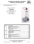
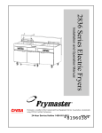
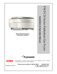
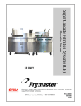
YPF95 Series Portable Filtration Systems Installation & Operation Manual Frymaster, a member of the Commercial Food Equipment Service Association, recommends using CFESA Certified Technicians. JUNE 2007 24-Hour Service Hotline 1-800-551-8633 `8196325~ Please read all sections of this manual and retain for future reference. Installation, maintenance, and repairs should be performed by your Frymaster/Dean Factory Authorized Service Agency. WARNING Safe and satisfactory operation of your equipment depends on its proper installation. Installation MUST conform to local codes, or in the absence of local codes, with the latest edition of the National Electric Code, N.F.P.A. 70. WARNING ELECTRICAL GROUNDING INSTRUCTIONS This filter is equipped with a three-prong, grounded plug for your protection against shock hazard and should be plugged directly into a properly grounded, three-hole receptacle. Do not cut off, remove or otherwise bypass the grounding prong on this plug. If it is necessary to use an extension cord, it MUST be a three-conductor, grounded cord of 16 gauge or greater. DANGER Do not filter more than one fry tank at a time. Hot fluid – Do not fill above a point 1-½ inch below the OIL CONTAINER RIM. WARNING This filter unit is not suitable for outdoor use. When operating this unit, it MUST be placed on a horizontal surface. WARNING This filter unit is not suitable for installation in an area where a water jet can be used, and this appliance MUST NOT be cleaned with a water jet. NOTICE: If this filter unit is cleaned with water, disconnect the unit from power source before cleaning and thoroughly dry the filter unit before reconnecting to electrical power source. DANGER The optional crumb tray (if equipped) in portable filter systems must be emptied into a fireproof container at the end of frying operations each day. Some food particles can spontaneously combust if left soaking in certain shortening material. NOTICE: Drawings and photos used in this manual are intended to illustrate operational, cleaning and technical procedures and may not conform to on-site management operational procedures. NOTICE IF, DURING THE WARRANTY PERIOD, THE CUSTOMER USES A PART FOR THIS ENODIS EQUIPMENT OTHER THAN AN UNMODIFIED NEW OR RECYCLED PART PURCHASED DIRECTLY FROM FRYMASTER/DEAN, OR ANY OF ITS AUTHORIZED SERVICE CENTERS, AND/OR THE PART BEING USED IS MODIFIED FROM ITS ORIGINAL CONFIGURATION, THIS WARRANTY WILL BE VOID. FURTHER, FRYMASTER/DEAN AND ITS AFFILIATES WILL NOT BE LIABLE FOR ANY CLAIMS, DAMAGES OR EXPENSES INCURRED BY THE CUSTOMER WHICH ARISE DIRECTLY OR INDIRECTLY, IN WHOLE OR IN PART, DUE TO THE INSTALLATION OF ANY MODIFIED PART AND/OR PART RECEIVED FROM AN UNAUTHORIZED SERVICE CENTER. YPF95 Series Portable Filtration Systems Installation & Operation Manual TABLE OF CONTENTS Page # 1. INTRODUCTION 1-1 2. IMPORTANT INFORMATION 2-1 3. INSTALLATION INSTRUCTIONS 3-1 4. FILTER OPERATION 4-1 5. CLEANING AND MAINTENANCE 5-1 6. TROUBLESHOOTING 6-1 7. PARTS LIST 7-1 YPF95 SERIES PORTABLE FILTRATION SYSTEMS CHAPTER 1: INTRODUCTION 1.1 Parts Ordering/Service Information Place parts orders directly with your local Frymaster/Dean Factory Authorized Service Center. A list of FASCs was included with the filter when shipped from the factory. If you do not have access to this list, please contact the Frymaster/Dean service department at 1-800-551-8633 or 1-318-8651711, or go to Frymaster/Dean’s website at: www.frymaster.com. To help speed your order, the following information is required: Model Number Serial Number Optional Features Type Item Part Number Quantity Needed 1.2 Service Information Call the 1-800-551-8633 or (318) 865-1711 Service Hotline number for the location of your nearest Factory Authorized Service Center. Always give the model and serial numbers of your filter unit. Also, identify if your unit is supplied with or without a heater. To assist you more efficiently, the following information will be needed: Model Number Serial Number Type Optional Features Nature of Problem: Additional information (i.e. oil temperature at filter time, time of day and other pertinent information) may be helpful in solving your service problem. 1-1 YPF95 SERIES PORTABLE FILTRATION SYSTEMS CHAPTER 1: INTRODUCTION 1.3 After Purchase In order to improve service, have the following chart filled in by the Dean Authorized Service Technician who installed this equipment. Authorized Service Technician/FASC Address Telephone/Fax Model Number Serial Number 1.4 Safety Information Before attempting to operate your unit, read the instructions in this manual thoroughly. Throughout this manual, you will find notations enclosed in double-bordered boxes similar to the ones below. CAUTION CAUTION boxes contain information about actions or conditions that may cause or result in a malfunction of your system. WARNING WARNING boxes contain information about actions or conditions that may cause or result in damage to your system, and which may cause your system to malfunction. DANGER DANGER boxes contain information about actions or conditions that may cause or result in injury to personnel, and which may cause damage to your system and/or cause your system to malfunction. 1-2 YPF95 SERIES PORTABLE FILTRATION SYSTEMS CHAPTER 1: INTRODUCTION 1.5 Service Personnel Definitions A. Qualified and/or Authorized Operating Personnel Qualified/authorized operating personnel are those who have carefully read the information in this manual and have familiarized themselves with the equipment functions, or have had previous experience with the operation of equipment covered in this manual. B. Qualified Installation Personnel Qualified installation personnel are individuals, firms, corporations, or companies that are responsible for the installation of electrical appliances, either in person or through a representative. Qualified personnel must be experienced in such work, be familiar with all electrical precautions involved, and have complied with all requirements of applicable national and local codes. C. Qualified Service Personnel Qualified service personnel are those who are familiar with Frymaster/Dean equipment and have been authorized by Frymaster/Dean to perform service on Frymaster/Dean equipment. All authorized service personnel are required to be equipped with a complete set of service parts manuals and stock a minimum amount of parts for Frymaster/Dean equipment. A list of Frymaster/Dean Factory Authorized Service Centers (FASCs) was included with the fryer when shipped from the factory. Failure to use qualified service personnel will void the Frymaster/Dean warranty on your equipment. 1-3 YPF95 SERIES PORTABLE FILTRATION SYSTEMS CHAPTER 2: IMPORTANT INFORMATION 2.1 General YPF95 portable filters can be used with a variety of Frymaster fryers, as well as other manufacturers’ equipment. Oil capacity is approximately 105 pounds. Unit specifications are listed below. Model YPF95 Unit Height (inches) 53 Unit Width (inches) 18 Unit Length (inches) 33 ¼ Tank Height (inches) 9 YPF95 Series filter unit dimensions (unit and tank heights are measured from bottom of casters to top of unit and tank, respectively). 2-1 Oil Capacity (pounds) 105 YPF95 SERIES PORTABLE FILTRATION SYSTEMS CHAPTER 2: IMPORTANT INFORMATION 2.1 General (cont.) Oil or shortening is gravity-drained from the fryer into the filter, and then filtered through filter paper. Filter powder, which enhances the filtering process, is distributed over the paper prior to filtering. All units are shipped completely assembled with accessories packed inside the filter pan. All units are adjusted, tested and inspected at the factory before shipment. WARNING The on-site supervisor is responsible for ensuring that operators are made aware of the inherent dangers of operating a hot oil filter system, particularly the aspects of oil filtration, and draining/cleaning procedures. An ON/OFF switch activates/deactivates the filter pump, and a 7-amp (120V), or 5-amp (230V) circuit breaker switches the power OFF if an overload occurs. An internal backup thermaloverload switch on the pump-motor provides additional protection. NOTE: If the circuit breaker is triggered, depress the reset button to activate the circuit after the failure has been detected and repaired. 2.2 Rating Plate Information on the rating plate includes model and serial numbers, as well as electrical requirements. The rating plate is located on the back housing, near the electrical receptacle. Have the rating plate information handy when communicating with the factory about a unit or requesting special parts or information. Without rating plate information, proper identification of the unit cannot be confirmed. 2-2 YPF95 SERIES PORTABLE FILTRATION SYSTEMS CHAPTER 2: IMPORTANT INFORMATION 2.3 Pre-Installation NOTE: Failure to use qualified service personnel will void the Frymaster/Dean warranty. A. Standards: Use of this filter unit must be in accordance with all applicable state and local codes. B. Electrical Connections: Domestic YPF95 filter units require a 115V 60 Hz., 15 amp electrical supply. International/CE units require 230V 50 Hz., 7 amp electrical supply. Units are equipped with a grounded male receptacle for use with a 16-3 SJT power cord set. If an extension cord is required, it must be a three-conductor, grounded power cord of at least 16 gauge. 2.4 Unpacking the Filter System Ensure the container is upright. Unpack the filter carefully and remove all accessories from the carton. Do not discard or misplace parts and/or accessories; they will be needed for filter setup and operation. Any accessories or starter kits included with the unit will be packaged inside the filter tank. After unpacking, immediately check the equipment for visible signs of shipping damage. If such damage has occurred, contact the carrier and file the appropriate freight claims. Do not contact the factory, as the responsibility of shipping damage is between the carrier and dealer or end-user. If your equipment arrives damaged: a. File claim for damages immediately – Regardless of extent of damage. b. Visible loss or damage – Be sure this is noted on the freight bill or express receipt and is signed by the person making the delivery. c. Concealed loss or damage – If damage is unnoticed until equipment is unpacked, notify freight company or carrier immediately, and file a concealed damage claim. This should be done within 15 days of date of delivery. Retain the shipping container for inspection. NOTE: Frymaster does not assume responsibility for damage or loss incurred in transit. 2-3 YPF95LP SERIES PORTABLE FILTRATION SYSTEMS CHAPTER 3: FILTER PREPARATION 3.1 Assembling The Filter System On initial installation and before each use, remove all loose parts from the filter, wash the filter pan and all accessories in hot, soapy water and dry thoroughly. WARNING! Water or boil-out solution MUST not be allowed to drain into the filter pan or filter system. Irreversible damage will result if water is allowed into the system, and the warranty will be voided. YPF95 Series portable filtration systems use a filter support grid, one sheet of filter paper and a hold-down ring to secure the filter paper in place. 2 3 See illustration for proper assembly. 1 4 1. 2. 3. 4. 5. 6. Filter Pan Cover Front Filter Pan Cover Rear Hold-Down Ring Filter Paper (one sheet) Screen/Sana Grid Filter Pan Assembly 5 6 A. First, place the Sana Grid in the bottom of filter pan. B. Place one sheet of filter paper on top of the Sana Grid. Ensure the paper evenly covers the filter pan bottom. C. Position the hold-down ring on top of the filter paper securely against the filter pan bottom, forming a tight seal. D. Sprinkle 8 ounces of filter powder over the filter paper, distributing the powder as evenly as possible. If filtering a second frypot immediately after the first, add only 4 ounces of filter powder for the second filtering. E. Place filter pan covers onto the filter pan assembly. F. Position filter in the space between the two fryers. Lock the rear casters to prevent filter from moving out of position during the filtering process. 3-1 YPF95 SERIES PORTABLE FILTRATION SYSTEMS CHAPTER 3: FILTER PREPARATION -A- YPF95 portable filter positioned correctly between two fryers with rear casters locked in place. G. Align the drain pipes over the front filter pan cover. Remove the front cover and replace it with the oil baffle (as shown below). The baffle should sit on the hold-down ring inside the filter pan and will prevent splashing during filtration. 2 1 4 Remove the front filter pan cover and insert the oil baffle to prevent splashing and movement during filtering. The oil baffle fits straight down over the two drain tubes and rests on the hold-down ring frame. 3-2 3 1. 2. 3. 4. 4 Oil Baffle (remove front lid) Filter Pan Cover, Rear Filter Pan Drain Tube (fryer to filter) YPF95 SERIES PORTABLE FILTRATION SYSTEMS CHAPTER 4: FILTER OPERATION 4.1 General YPF95 Series portable filters are designed to operate primarily as an independent filter unit. Operations always start by ensuring the unit is properly plugged in and situated in the filter space between the fryers. The general layout of a YPF95 Series portable filter with major components identified is illustrated below. Arrows indicate direction of oil flow during the filtration process. 4-1 YPF95 SERIES PORTABLE FILTRATION SYSTEMS CHAPTER 4: FILTER OPERATION 4.2 Filtering Tools These tools are not required, but are recommended to make the filtering task easier. A. Measuring Cup: Used to measure eight ounces by volume of filter powder. B. Scrub Brush: To clean sediment and residue from the filter pan and frypot. C. Appropriate Clothing. 4.3 Filter Preparation 1. Ensure the YPF95 portable filter is positioned between fryer(s) it is being used to filter. The casters must be locked in place and the faucet must be over an appropriate frypot. Remove the front filter pan lid and place the oil baffle over the drain pipes and into the uncovered portion of the filter. 2. Ensure the filter power switch is in "OFF" position prior to connecting to power supply. 3. Plug power cord into electrical outlet. The filter unit is ready for filtering. After filtering, follow instructions in Section 4.4, Changing Filter Paper. DANGER The crumb tray (if equipped) in portable filter systems must be emptied into a fireproof container at the end of frying operations each day. Some food particles can spontaneously combust if left soaking in certain shortening material. 4.4 Changing Filter Paper Filter paper should be replaced after each filter session, and most certainly at the beginning of each workday. If filter paper is replaced once per day, excess sediment should be scraped from the filter paper after each frypot is filtered (see photo). Use care not to tear the paper when scraping off sediment. Filter at closing if possible. This ensures the oil is at proper filtering temperature. Note: If filtering at closing, remove and discard the used filter paper in a fireproof container when filter operations are complete. Wash all components in soapy water and dry completely. Remove and replace the paper as follows: 1. Remove filter covers and/or oil baffle and move the filter away from the fryers and into an open area. 2. Lift the hold down ring out of the filter pan. 3. Roll both ends of the filter paper into the center, ensuring no sediment falls out, and discard. 4-2 YPF95 SERIES PORTABLE FILTRATION SYSTEMS CHAPTER 4: FILTER OPERATION 4.4 Changing Filter Paper (cont.) 4. Remove and check the Sana Grid for cleanliness and clean if necessary. 5. Check the filter-pan for cleanliness and clean if necessary; check the drain ports at the bottom rear of the filter pan and clear any solidified shortening from the opening (black arrow). 6. Replace the Sana Grid and place a new sheet of filter paper on top of the screen. 7. Replace the hold-down ring in the filter pan on top of the filter paper. 8. Measure 8 ounces of filter powder and distribute evenly over the surface of the paper. 9. Replace the filter pan covers and slide it back into place between the appropriate fryers. Plug in the filter. It is now ready for operation. Filter assembly. 4.5 Unit Operation When filtering, follow these steps: 1. Follow the appropriate instructions in Sections 4.3 and 4.4 to prepare the filter unit for operation. 2. Position the oil baffle over the drain pipes extending from the side of each fryer. It should sit on the hold down ring in the bottom of the filter pan. 3. Turn the fryer main power switch to the "OFF" position. 4-3 YPF95 SERIES PORTABLE FILTRATION SYSTEMS CHAPTER 4: FILTER OPERATION 4.5 Unit Operation (cont.) DANGER Do not leave filter unit unattended during the filtering operation. Avoid spilling hot oil onto floor surfaces. When draining fryer into filter, never exceed the maximum capacity of the filter pan. DANGER The oil temperature of the fryer to be filtered should be approximately 350°F (175°C). Position drain handles properly prior to operating the filter unit. Failure to do this can result in burn injury to the user. 4. Open the drain valve and allow the frypot oil to drain into the filter pan. 5. Ensure that the YPF95 filter faucet is located over the correct frypot. Turn the filter switch "ON" to begin pumping filtered oil back into the fryer. Allow the oil to recycle through the fryer for a few seconds to wash out sediment on the bottom of the frypot before closing the drain valve. NOTE: The oil return wand can also be mounted in the wand holster inside the pan, for extended filtering periods (polishing) prior to refilling frypot. NEVER LEAVE THE FILTER SYSTEM UNATTENDED WHILE FILTERING! 6. When filtering is complete, close the drain valve handle. It takes approximately 5 to 7 minutes for the filter to pump all the oil back into the fryer. 7. Before shutting off the filter, allow the pump to run for 10-15 seconds after air starts to sputter through the faucet. Clearing residual shortening or oil from the return lines reduces the likelihood of clogged lines. NOTE: After filtering, scrape off debris and sediment accumulated on the filter paper and discard into a fireproof container. CAUTION If using solid shortening, the return hose must be completely drained after filtering, or the shortening will solidify and plug the hose or oil return lines as it cools. NOTE: If filtration operations problems are encountered during use, please refer to Chapter 6 in this manual. 4-4 YPF95 SERIES PORTABLE FILTRATION SYSTEMS CHAPTER 5: PREVENTATIVE MAINTENANCE 5.1 General Cleaning operations fall into three general categories: • Wiping unit clean, interior and exterior, after each filter session. • Cleaning, changing filter paper and preparing the unit for the next day’s business. • Weekly cleaning to remove oil deposits and other particles that were previously missed. WARNING Do not use water jets to clean this equipment. To do so will damage the unit and void the warranty. WARNING Never operate the filter unit unless cooking oil is at operating temperature. 5.2 Each Filter Use Each time the portable filter is used: • Wash down the insides of the filter pan with hot oil during the filtering process. DO NOT allow excessive residue buildup to occur inside the filter pan. • Change filter paper after each filter session or at the end of the day. Scrape sediment from filter paper after each frypot is filtered within a filter session. Do not filter more than three fryers per one sheet of filter paper. • Wipe up any oil which may have splashed or spilled. • Wipe all exterior surfaces of the filter unit. WARNING Do not run water or boil-out solution through the portable filter. Doing so will cause irreparable damage to the pump, and void the warranty. 5-1 YPF95 SERIES PORTABLE FILTRATION SYSTEMS CHAPTER 5: PREVENTATIVE MAINTENANCE 5.3 Daily: Close Of Business At the close of a working day, filter the oil in all fryers. When the last fryer is finished, follow these steps: 1. Ensure the flexible hose and pump lines are clear by running the filter pump for an additional 10–15 seconds after the faucet begins to bubble. 2. Discard the filter paper in a fireproof container after use. 3. Remove the filter pan cover and hold-down ring assembly, and then remove the filter paper and Sana Grid. 4. Wash all filter components with soapy water and rinse. 5. Dry all filter parts and the filter pan thoroughly before reassembling. 6. Check all fittings on the filter unit and ensure that they are properly tightened. DANGER The crumb tray (if applicable) in portable filter systems must be emptied into a fireproof container at the end of frying operations each day. Some food particles can spontaneously combust if left soaking in certain shortening material. 5.4 Weekly Follow the same procedure as for "Daily", with these additional steps: • Wash the filter pan with hot, soapy water and a brush. Dry and reassemble with new filter paper. • Clean thoroughly under, around, and behind the fryers and filtering area. • Do not operate motor/pump until all traces of water have been removed from the pan. Under no circumstances should water or boil-out solution be allowed to enter the pump housing; irreparable damage will result, and all warranties will be voided. • Check the connections of the inlet lines and tighten if lines become loose or start to leak oil. 5-2 YPF95 SERIES PORTABLE FILTRATION SYSTEMS CHAPTER 6: TROUBLESHOOTING 6.1 Operating Problems Plugged lines and plugged filter paper account for over 90 percent of filtration system malfunctions. A general troubleshooting chart included in this chapter provides systematic instructions to assist the operator in diagnosing common malfunctions. Contact a factory-authorized service technician for troubleshooting beyond the scope of the operator. A. Plugged Lines To guard against plugged lines when using solid shortening, let the faucet sputter for about 10-15 seconds at the end of each filter cycle. This will allow air to move through the lines and keep them from becoming to be plugged. B. Filter Powder and Plugged Paper Improper use of the filter powder will cause filter paper to become plugged, sealed by a layer of filter powder and debris. The first indication of paper plugging is a slow oil flow return rate and a surging, jerking in the filter unit. To correct this, review the instructions for the correct use of filter powder, and change the filter paper more frequently. When filtering several fryers prior to changing paper, ensure that excess sediment is scraped off the filter paper after filtering each frypot. If plugged paper remains a problem, review the chart in section 6.2 for proper diagnosis. 6.2 General Troubleshooting The following chart contains information to assist the user in diagnosing the most common malfunctions with portable filtration systems. Possible solutions and/or corrective actions are given for each scenario. If the malfunction cannot be diagnosed using the information in this section, contact your Factory Authorized Service Agent for repairs. DANGER Use extreme care when testing electrical circuits. Live circuits will be exposed. DANGER Inspection, testing and repair of gas or electrical equipment should be performed by qualified personnel. 6-1 YPF95 SERIES PORTABLE FILTRATION SYSTEMS CHAPTER 6: TROUBLESHOOTING 6.2 General Troubleshooting (cont.) Pump won't start. - Tripped circuit breaker. Incorrect or no line voltage. Allow filter unit to cool for at least 45 minutes and then press the pump reset button on the side of the filter. - Turn filter pump "OFF". Allow oil to cool then empty pan. Verify filter paper is clean and properly installed. Refill pan and restart process. - Pump stops during filtering process. Reset circuit breaker. Pump is blocked or wiring is loose. Call FASC for service. - Filter pan suction tube is blocked. Use a thin, flexible wire to unclog. - Motor failed; call FASC for service. - Pump starts and abruptly stops. Pumping is erratic. Oil not being returned to frypot. - Verify that filter paper is properly installed under hold-down ring. Solidified oil or sediment is likely clogging the filter hose. Clear hose. - Clogged filter paper. Scrape off excess sediment or replace filter paper. - 6-2 YPF95 SERIES PORTABLE FILTRATION SYSTEMS CHAPTER 6: TROUBLESHOOTING 6.3 Wiring Diagrams 6.3.1 YPF95 120V Wiring Switch Housing Receptacle BLK BLK BLK BLK GRN WHT ON/OFF Switch CB 7 Amp Circuit Breaker 120 VAC BLK C P1 NC BLK Thermal Overload Reset Switch P2 T3 T8 T2 T4 WHT T5 Motor Terminal Box Electrical Junction Box 120/230 VAC, 50/60 Hz Motor w/Thermal Overload Protector 6.3.2 YPF95 230V Wiring Switch Housing Receptacle BRN BLK ON/OFF Switch GRN-YEL BLU CB 5 Amp Circuit Breaker 230 Volt BLK P1 T2 T3 T8 C NC BLK Thermal Overload Reset Switch T4 T5 BLU Electrical Junction Box Motor Terminal Box (120/230V, 50/60 Hz Motor W/Thermal Overload Protector) 6-3 YPF95 SERIES PORTABLE FILTRATION SYSTEMS CHAPTER 7: PARTS LIST 7 Main Components 7-1 YPF95 SERIES PORTABLE FILTRATION SYSTEMS CHAPTER 7: PARTS LIST 7 Main Components Item Part # 1 106-4589 2 Description Filter Pan Assembly 200-8685 Sana Grid Screen 211-8703 Stiffener, Pan Frame, Left 212-8703 Stiffener, Pan Frame, Right 809-0417 Nut, Flange, ¼"-20, Serrated 810-1057 Flex Line, 5/8" OD x 13" Long 810-1668 Adaptor, Male, 5/8" OD x ½" 813-0062 Elbow, ½", 90°, Black Metal 823-5022 Hold Down Ring 823-5057 Filter Pan 106-4608 Filter Pan Lid, Rear (larger) 824-1459 Lid, Filter Pan 810-0180 Handle, Filter Pan Lid 809-0918 Screw, 10-24 x ½" 809-0191 Washer, ¼" Spring Lock 3 106-4610 Rear Panel, Filter 4 106-4613 Cover Assembly, Top of Arm 5 106-4647 Plumbing, Oil Return 6 106-8342 Filter Pan Cover, Front 7 200-8887 Cover, Filter Plug 8 210-8733 Handle, Filter Unit 9 210-8741 Pump Housing 10 211-8723 Bracket, Handle, LT 11 211-8825 Clip, 5/8", Handle, LT 12 212-8723 Bracket, Handle, RT 13 212-8825 Clip, 5/8", Handle, RT 14 806-6034 Pump/Motor 115V, 60 Hz 15 807-1041 Switch, Toggle, 120V, 15A 16 807-1043 Bushing, 1.06 ID Heyco 17 807-1219 Receptacle, 120V, 3 wire 18 807-2469 Bushing, 1" ID, Heyco 19 809-0059 Nut, Grip ¼-20 x ¾ 20 809-0120 Screw,10-32 x ½" Truss Head 21 809-0131 Screw, Hex Head ¼"-20 x ¾ 22 809-0189 Washer, ¼" SAE Plain 23 809-0256 Nut, Hex Keps 10-32 24 809-0412 Screw, #10-1/2, Hex Head 7-2 YPF95 SERIES PORTABLE FILTRATION SYSTEMS CHAPTER 7: PARTS LIST 7 Main Components Item Part # Description 25 809-0417 Nut, Flange, ¼"-20 Serrated 26 809-0449 Screw, #10 x ½", Phillip's Truss Head 27 810-1668 Adaptor, Male 5/8" OD x ½" 28 810-2699 Coupling, Quick Disconnect, Snaptite 29 810-2700 Nipple, Quick Disconnect, Snaptite 30 810-2805 Caster, 2", Filter Pan 31 810-2806 Caster, 2" with Brake, Filter Pan 32 810-2957 Tubing, Faucet, Over-the-Top 33 813-0006 Bushing, Hex ½" to 3/8" NPT, Black Metal 34 813-0022 Nipple, ½" x Close NPT, Black Metal 35 813-0062 Elbow,1/2", 90°, Black Metal 36 813-0093 Nipple, ½" x 4" NPT, Black Metal 40 813-0625 Nipple,3/8" x Close NPT, Black Metal 41 823-5026 Frame, Portable Filter 42 823-5027 Tube, Oil Return 43 823-6381 Tube, Oil Return, Over-the-Top 44 824-1460 Cover, Housing Top 45 824-1479 Plate, Filter Pump * 813-0165 Elbow, Street, ½" x ½" NPT, 90°, Black Metal * 813-0247 Nipple,1/2" x 3.50 NPT, Black Metal Pipe * 813-0265 Nipple, ½" x 2.50 NPT, Black Metal * Not Illustrated 7-3 THIS PAGE INTENTIONALLY LEFT BLANK Frymaster, L.L.C., 8700 Line Avenue, PO Box 51000, Shreveport, Louisiana 71135-1000 Shipping Address: 8700 Line Avenue, Shreveport, Louisiana 71106 TEL 1-318-865-1711 FAX (Parts) 1-318-219-7140 PRINTED IN THE UNITED STATES FAX (Tech Support) 1-318-219-7135 SERVICE HOTLINE 1-800-551-8633 819-6325 JUNE 2007