1
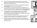
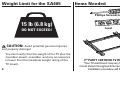
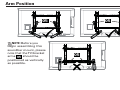
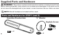
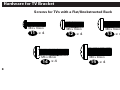
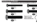
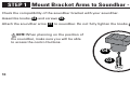
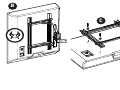
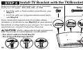
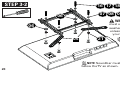
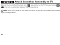
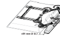
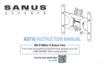
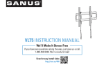
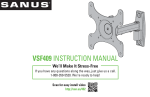
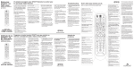
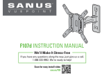
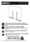
SA405 INSTRUCTION MANUAL We’ll Make It Stress-Free If you have any questions along the way, just give us a call: 1-800-359-5520 we’re ready to help! IMPORTANT SAFETY INSTRUCTIONS – SAVE THESE INSTRUCTIONS – PLEASE READ ENTIRE MANUAL PRIOR TO USE Before You Begin Please check the following items: Your TV and any accessories you plan to use do not exceed the specified weight limit of your TV wall mount. You read and understand these directions. You refer to the documentation that came with your sound bar and TV wall mount for additional guidance. You have the tools needed for installation. If you have any questions, please contact Customer Service: 1-800-359-5520. • • 2 WARNING: This soundbar mount is only designed to be used with TV wall mounts that meet third party safety certifications. This soundbar mount is only designed to mount sound bars BELOW the television (see Figure 1). • • • • • • If the TV wall mount does not include TV interface spacers; do not use the TV interface spacers included with this soundbar mount. If the TV wall mount has built-in or integrated spacers (see Figure 2); do not use this product. This soundbar mount should only be installed into TV interface bracket slots or holes that are less than 11 mm (.43 in.) wide; do not over-tighten washer (see Figure 3). This soundbar mount was designed to be installed and utilized only as specified in this manual. The manufacturer is not responsible for improper assembly, use, or handling of this product. The wall must be capable of supporting five times the weight of the TV, mount, and soundbar combined. Failure to follow these instructions could result in an unstable situation that may result in property damage or personal injury. Figure 1 TV Soundbar Figure 2 Figure 3 3 Weight Limit for the SA405 Items Needed Phillips Screwdriver 15 lb (6.8 kg) DO NOT EXCEED! Level CAUTION: Avoid potential personal injuries and property damage! You must verify that the weight of the TV plus the soundbar mount, soundbar, and any accessories is lower than the maximum weight rating of the TV mount. 4 3RD PARTY CERTIFIED TV WALL MOUNT* *Your TV wall mount may vary from the TV wall mount shown throughout this manual. That is OK. The installation procedure will be the same. Arm Position 05 NOTE: Before you begin assembling this soundbar mount, please note that the TV/bracket arms 05 should be positioned as vertically as possible. 05 05 5 Supplied Parts and Hardware WARNING: This product contains small items that could be a choking hazard if swallowed. Before starting assembly, verify all parts are included and undamaged. If any parts are missing or damaged, do not return the damaged item to your dealer; contact Customer Service. Never use damaged parts! NOTE: Not all hardware included will be used. Parts and Hardware for STEP 1 (and 3) Soundbar Bracket Arm “C” Washer Knob Keyhole Screw 03 x 2 01 x 2 6 02 x 2 04 x 4 Parts and Hardware for STEP 3 Hardware for TV Bracket TV Screw Washers TV Bracket Arm 05 x 2 Soundbar Mount Spacer 06 x 2 M4/M5 M6/M8 07 x 4 08 x 4 Large M4/M5 Large M6/M8 09 x 4 10 x 4 7 Hardware for TV Bracket Screws for TVs with a Flat/Unobstructed Back M4 x 16mm 11 x 4 M6 x 25mm 14 x 4 8 M5 x 16mm M6 x 16mm 12 x 4 13 x 4 M8 x 20mm 15 x 4 Hardware for TV Bracket Screws for TVs with Irregular/Obstructed Backs M4 x 40mm 16 x 4 M5 x 40mm 17 x 4 M6 x 40mm M6 x 50mm 18 x 4 19 x 4 M8 x 40mm 20 x 4 Spacer for TVs with Irregular/ Obstructed Backs 21 x 4 9 STEP 1 Mount Bracket Arms to Soundbar - Option 1 Check the compatibility of the soundbar bracket with your soundbar. Assemble knobs 04 and screws 03 . Attach the soundbar arms 01 to soundbar. Do not fully tighten the knobs 04 . NOTE: When planning on the position of the soundbar, make sure you will be able to access the control buttons. 04 03 10 04 01 01 03 11 STEP 1 Mount Bracket Arms to Soundbar - Option 2 Check the compatibility of the soundbar bracket with your soundbar. Assemble knobs 04 and screws 03 . Some connections to the soundbar may require a “C” washer 02 to ensure that the soundbar arms 01 lay flat on the soundbar. If required, slip a “C” washer 02 onto the knob screws 03 and under the arms 01 and loosely tighten the knobs 04 . NOTE: When planning on the position of the soundbar, make sure you will be able to access the control buttons. 04 03 12 04 02 02 01 04 01 04 02 03 13 STEP 1 Mount Bracket Arms to Hanger - Option 3 Some soundbars will come with a manufacturer supplied hanger. Attach the soundbar arms 01 to the soundbar hanger with knobs 04 and screws 03 . Do not fully tighten the knobs 04 . NOTE: When planning on the position of the soundbar, make sure you will be able to access the control buttons. 14 04 01 01 SOUNDBAR MANUFACTURER SUPPLIED HANGER 03 15 STEP 2 Prepare TV If your TV is already mounted: A. B. Remove any cables attached to the TV. Remove the TV/bracket assembly from the wall plate, arm assembly, or pillar. Please see your TV wall mount installation manual for guidance. HEAVY! You may need assistance with this step! C. Remove the TV bracket from the TV. IMPORTANT! ! Please see your TV wall mount manual for instructions on how to remove the TV interface bracket. ! Save the TV hardware in case you want to use the TV without the soundbar in the future. ! You must use the hardware provided with this product instead of the hardware that came with your mount. 16 A B C 17 STEP 3 Install TV Bracket with the TV/Bracket Arms Determine the bolt diameter for your monitor and your TV type - M4, M5, M6, or M8. • For TVs with a flat/unobstructed back, see Step 3-1 • For TVs with an irregular/obstructed back, see Step 3-2 If you need extra space to accommodate cables, recesses, or protrusions, see Step 3-2 that uses spacers. Standard configurations are shown. For special applications, contact Customer Service. CAUTION: Verify adequate thread engagment with the screw or screw/spacer combination. - Too short will not hold the TV. - Too long will damage the TV. 18 Step 3-1 Step 3-2 STEP 3-1 11 12 13 14 15 07 08 09 10 06 WARNING: You must use the larger washers 09 or 10 unless they do not fit your TV bracket. 06 05 NOTE: Install screws but do not fully tighten before Step 6. NOTE: Soundbar must be mounted below the TV as shown. 19 STEP 3-2 16 17 18 19 20 07 08 09 10 06 WARNING: You must use the larger washers 09 or 10 unless they do not fit your TV bracket. 06 05 20 21 NOTE: Install screws but do not tighten before Step 6. NOTE: Soundbar must be mounted below the TV as shown. CAUTION: The end of the TV/bracket arms 05 must not extend beyond the edge of the TV. 05 05 21 STEP 4 Attach Soundbar Assembly to TV Attach the soundbar/bracket arm 01 assembly to the TV/bracket arms 05 using knobs 04 . Do not completely tighten the connections. NOTE: You may need to use trial and error to get the soundbar TV brackets set to the right configuration. 22 Options 1 and 2 04 Option 3 04 01 05 01 05 04 04 01 01 05 05 23 STEP 5 Adjust Arms Adjust the soundbar/bracket arms 01 and the TV/bracket arms 05 until soundbar or hanger is the in desired position. NOTE: Final position of soundbar must be within 51 mm (2 in.) of the TV. 24 05 01 ≤51 mm (2 in.) 25 STEP 6 Tighten Connections When soundbar or hanger is in the desired position, tighten all connections. Do not over-tighten washer. This could cause the washer to deform. 26 STEP 7 Hang Assembly Follow your TV wall mount installation manual to re-hang the assembly. Options 1 and 2 Option 3 27 ESPAÑOL INSTRUCCIONES DE SEGURIDAD IMPORTANTES. CONSÉRVELAS. LEA TODO EL MANUAL ANTES DE UTILIZAR ESTE PRODUCTO. Antes de comenzar Revise los siguientes puntos: Que su televisor y cualquier accesorio que vaya a utilizar no excedan el límite de peso especificado del soporte del televisor. Que va a leer y que comprende estas indicaciones. Que va a consultarla documentación que viene con su televisor para ver otras instrucciones. Que tiene las herramientas necesarias para la instalación. Comuníquese con el Servicio de Atención al Cliente si tiene alguna pregunta: 1-800-359-5520. • 28 ADVERTENCIA: El soporte para barra de sonido debe utilizarse únicamente con placas murales para televisor que cumplan con las normas de seguridad con certificación de un tercero. • • • • • • • ESPAÑOL El soporte para barra de sonido solo permite instalar barras de sonido debajo del televisor (ver Figura 1). Si la placa mural para televisor no incluye separadores para televisor, no utilice los separadores para televisor incluidos en este soporte de barra de sonido. No utilice este producto si la placa mural para televisor ya incorpora o cuenta con separadores integrados (ver Figura 2). Instale el soporte para barra de sonido solamente sobre los soportes de acoplamientos u orificios de montaje con menos de 11 mm (0.43”) de ancho. No ajuste la arandela en exceso (ver Figura 3). Instale y utilice el soporte para barra de sonido únicamente como se indica en este manual. El fabricante no se hace responsable por daños derivados de uso, instalación o manejo incorrectos de este producto. La pared debe soportar cinco veces el peso del televisor, del soporte y de la barra de sonido juntos. En caso de no seguir estas instrucciones, la instalación podría volverse inestable y provocar lesiones físicas o daños a la propiedad. 29 ESPAÑOL Límite de peso para el SAA405 6,8 kg (15 libras) ¡NO LO EXCEDA! PRECAUCIÓN: Evite lesiones y daños materiales. Debe verificar que el peso del televisor, junto con el soporte para la barra de sonido y los accesorios sea menor que el peso máximo permitido para el soporte del televisor. Piezas necesarias Destornillador Phillips Nivel PLACA MURAL PARA TELEVISOR CERTIFICADO POR UN TERCERO* *Su placa mural para televisor puede variar con respecto al modelo que se muestra en el manual de instrucciones. Esto es normal. El procedimiento de instalación será el mismo. 30 Posición del brazo NOTA: Los brazos del módulo televisor-placas 05 deben colocarse lo más verticales posible. Piezas y accesorios suministrados ADVERTENCIA: Este producto contiene piezas pequeñas que, si fuesen tragadas, podrían producir asfixia. Antes de iniciar el ensamblaje, compruebe que todas las piezas estén incluidas y en buenas condiciones. Si faltan piezas o alguna está dañada, no devuelva el artículo al distribuidor; póngase en contacto con el Servicio de Atención al Cliente. Nunca utilice piezas deterioradas. NOTA: No todos los accesorios incluidos deberán utilizarse. ESPAÑOL PASO 1 Instalar los brazos de la placa de sujeción a la barra de sonido (Opción 1) Verifique la compatibilidad de la placa de sujeción para barra de sonido con su barra de sonido. Ensamble las perillas 04 y tornillos 03 . Acople los brazos de la barra de sonido 01 a la barra de sonido. No ajuste completamente las perillas 04 . NOTA: Al planificar la ubicación de la barra de sonido, asegúrese de que podrá acceder a los botones de los controles. PASO 1 Instalar los brazos de la placa de sujeción a la barra de sonido (Opción 2) Verifique la compatibilidad de la placa de sujeción para barra de sonido con su barra de sonido. Ensamble las perillas 04 y tornillos 03 . Algunas conexiones de la barra de sonido pueden requerir una arandela en “C” 02 para asegurar que los brazos de la barra de sonido 01 permanezcan horizontales sobre la barra de sonido. Si es necesario, introduzca una arandela en “C” 02 sobre los tornillos de las perillas 03 y debajo de los brazos 01 y luego ajuste levemente las perillas 04 . 31 ESPAÑOL PASO 1 Instalar los brazos de la placa de sujeción al soporte (Opción 3) Algunas barras de sonido vienen con un soporte proporcionado por el fabricante. Acople los brazos de la barra de sonido 01 al soporte de la misma con las perillas 04 y los tornillos 03 . No ajuste completamente las perillas 04 . PASO 2 Preparar el televisor Si su televisor ya está instalado en un soporte: A. Retire todos los cables conectados al televisor. B. Retire el módulo televisor-placas de la placa mural, del brazo o del soporte vertical. Consulte el manual de instalación de la placa mural del televisor para ver las instrucciones. ¡ELEMENTO PESADO! Es posible que necesite ayuda en este paso. C. Retire la placa de sujeción del televisor. IMPORTANTE ! Consulte el manual de la placa mural del televisor para ver las instrucciones sobre cómo retirar el soporte de conexión del televisor. 32 ESPAÑOL ! Guarde los elementos de sujeción del televisor en caso de desear utilizar en el futuro el televisor sin la barra de sonido. ! Debe utilizar los elementos de sujeción proporcionados con este producto en lugar de aquellos que vinieron con el soporte. PASO 3 Instale la placa de sujeción del televisor con el módulo televisor-placas Determine el diámetro de los pernos para su monitor y su tipo de televisor: M4, M5, M6, o M8. • Para televisores con dorso plano/libre de obstrucciones, consulte el Paso 3-1 • Para televisores con dorso irregular/con obstrucciones, consulte el Paso 3-2 Si necesita más espacio para cables, concavidades o protuberancias, consulte el Paso 3-2 que utiliza separadores. Se ilustran las configuraciones estándar. En caso de aplicaciones especiales, comuníquese con el Servicio de Atención al Cliente. PRECAUCIÓN: Verifique que la combinación de tornillo y separador enrosque correctamente en su televisor. Si el tornillo es demasiado corto, el televisor no se sostendrá; si es demasiado largo, dañará el televisor. 33 ESPAÑOL PASO 3-1 PASO 3-2 ADVERTENCIA: Debe usar las arandelas más grandes 09 o 10 , a menos que no sean adecuadas para el soporte del televisor. NOTA: Coloque los tornillos pero no los ajuste completamente hasta el Paso 6. NOTA: La barra de sonido debe colocarse debajo del televisor, tal como se muestra. PRECAUCIÓN: Los extremos de los brazos del televisor/placa de sujeción 05 no deben sobrepasar el borde del televisor. PASO 4 Acople el módulo de la barra de sonido al televisor Fije el módulo barra de sonido/brazo 01 a los brazos del televisor/placa de sujeción 05 usando perillas 04 . No ajuste completamente las conexiones. NOTA: Es posible que deba usar el método de ensayo y error para lograr la configuración correcta del conjunto barra de sonido/placas de sujeción del televisor. 34 ESPAÑOL PASO 5 Ajuste los brazos Acomode los brazos de la barra de sonido/placa de sujeción 01 y los brazos del televisor/ placa de sujeción 05 hasta que la barra de sonido o el soporte de la misma se encuentre en la posición deseada. NOTA: La barra de sonido debe colocarse a una distancia máxima de 51 mm (2'') del televisor. PASO 6 Ajuste las conexiones Cuando haya colocado la barra de sonido o el gancho de soporte en la posición deseada, ajuste todos los tornillos. No ajuste la arandela en exceso. Si lo hace, esta podría deformarse. PASO 7 Colgar el módulo Siga las instrucciones del manual de instalación de la placa mural del televisor para volver a colgar el módulo. 35 Customer Service • 800-359-5520 • [email protected] SANUS • 6436 City West Parkway • Eden Prairie, MN 55344 USA ©2013 Milestone AV Technologies, a Duchossois Group Company. All rights reserved. Sanus is a division of Milestone. All other brand names or marks are used for identification purposes and are trademarks of their respective owners. 36 6901-002264 00