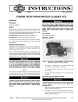
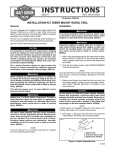
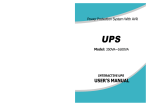
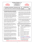
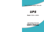
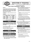
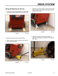
1
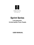
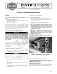
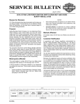
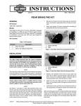
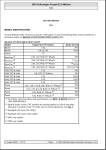
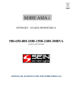
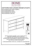
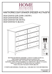
INSTRUCTIONS
®
REV. 01-23-04
-J03183
Kit Number 44531-04
DUAL DISC FRONT BRAKE KIT FOR DYNA
General
This kit is designed for installation on the following 2004 and later
DYNA FXD/I and FXDL/I model motorcycles which have original
equipment 39 mm front fork tubes (including chromed tubes),
handlebar and risers, and 19-in. cast-aluminum front wheels:
• 2004 - Later FXD/I (Super Glide)
• 2004 - Later FXDL/I (Low Rider)
This kit can also be installed on the above FXD/I and FXDL/I
models which have original equipment 39mm front fork tubes
and 19-in. laced front wheels only after one of the following procedures is performed:
• The original single-flange hub of the 19-in laced front
wheel is replaced with a new double-flange hub (H-D
part number 43976-04), (sold separately) which will
accept the second brake disc.
OR
• The original 19-in. laced front wheel assembly,
which has a single-flange hub, is replaced with a
new 19-in. laced front wheel assembly (H-D part
number 43591-04), (sold separately) which has a
double-flange hub designed to accept the second
brake disc.
1. Block motorcycle underneath frame so that front wheel is
raised off the ground slightly.
2. Refer to Service Manual procedures to remove the original
front brake caliper from left side of front fork. Let caliper
hang loose on brake line. Save all components and fasteners for reinstallation.
NOTE
Do not operate the front brake lever with the front caliper
removed because the piston may be forced from the caliper.
Reseating the piston requires disassembly of the caliper.
3. Remove socket head screw which secures a clamp
(retains front brake line) to underside of front fork lower
bracket (lower triple clamp). Discard clamp and screw.
4. See Figure 1. Remove screw, lockwasher, and clamp (1)
which secure front brake line to right rear side of front fork
upper bracket (2) (upper triple clamp). Save all components for reinstallation.
i06184.tif
1
2
See the Service Parts Illustration for a list of the contents included in this kit.
1WARNING
The rider’s safety depends on the correct installation of
this kit. Follow the procedures in this Instruction Sheet and
in the appropriate Service Manual(s). Service Manuals are
available at your Harley-Davidson dealer. If the procedures
are not within your capabilities, or if you do not have the
correct tools, have your Harley-Davidson dealer perform
the installation. Failure to follow instructions could result in
death or serious injury.
1WARNING
Brakes are a critical safety component. Contact a HarleyDavidson dealer for brake repair or replacement.
Improperly serviced brakes can adversely affect brake performance, which could result in death or serious injury.
(00054a)
Removal and Disassembly - Front Brake
System
NOTE
A Service Manual for your motorcycle is available at any HarleyDavidson Dealer.
1.
2.
Brake line clamp - upper
Front fork upper bracket
Figure 1. Upper brake cable clamp
5. Remove right mirror and, if applicable, right turn signal lamp
assembly from original front brake master cylinder casting.
Save all components and fasteners for reinstallation.
CAUTION
See Figure 2. Do not remove or install the master cylinder
assembly without first positioning a 5/32-inch (4mm) thick
cardboard insert between the brake lever and lever bracket.
Removing or installing the master cylinder assembly without the insert in place may result in damage to the rubber
boot and plunger on the front stoplight switch. (00324a)
NOTE
Use the eyelet of an ordinary cable strap if the cardboard insert
is not available.
6. See Figure 2. Squeeze the brake lever and place the cardboard insert between the brake lever and lever bracket.
1 of 6
Assembly and Installation - Front Fork Right
Slider/Tube
i05399
1. Assemble new right slider using new fork seal, dust seal
and retaining ring and drain screw from kit to original front
fork right tube assembly. Use new M8 - 1.25 x 27 mm hex
socket compression screw from kit. Follow procedures listed in appropriate Service Manual.
2. Install front fork right slider/tube assembly onto front fork
lower and upper brackets according to appropriate Service
Manual procedures.
5/32 in. cardboard insert
Figure 2. Install Insert Before Removing Master Cylinder
7. Using a T27 TORX drive head, remove the two screws with
flat washers securing the handlebar clamp to the master
cylinder housing. Remove the brake lever/master cylinder
assembly and clamp from the handlebar.
8. Save screws and clamp for reinstallation.
9. Lift assembly of master cylinder, brake line, and left caliper
away from motorcycle. Disconnect front brake line from left
front brake caliper at banjo fitting. Discard original master
cylinder, brake line, and banjo fitting sealing washers; save
original caliper and banjo bolt for reinstallation.
3. Fill front fork right slider/tube assembly with the proper “wet
fork” amount of Harley- Davidson Type E Fork Oil. Follow
procedures listed in appropriate Service Manual.
Assembly and Installation - Right Front Disc,
Wheel and Calipers
1. Verify that new front brake disc from kit is clean. With counterbored side of brake disc mounting holes facing away
from wheel, assemble brake disc to right side of front wheel
hub using five new 5/16 - 18 x 7/8 in. pan head screws
from kit. Use a T-40 TORX® drive to tighten each screw to
16-24 ft-lbs (21.7-32.5 Nm).
2. Place wheel into position between forks with the valve stem
on the right side of the vehicle.
3. Coat the axle with ANTI-SEIZE LUBRICANT.
1. Remove front wheel according to appropriate Service
Manual procedures.
4. See Figure 3. Supporting wheel, insert threaded end of axle
(1) through right fork leg. Push axle through fork, short
external spacer (not shown) and wheel hub until it begins to
emerge from left side.
2. Remove and discard five T-40 TORX screws which secure
hub plate to right side of wheel hub. Remove and discard
hub plate.
5. Push axle (1) through long external spacer (not shown)
and left fork leg until axle (1) shoulder contacts external
spacer on right fork side.
Removal and Disassembly - Front Fork Right
Slider/Tube
6. Install flat washer, lock washer and nut over threaded end of
axle.
Removal and Disassembly - Front Wheel
1. Remove front fork right slider/tube assembly from front fork
upper and lower brackets according to appropriate Service
Manual procedures.
2. Drain oil from front fork right slider/tube assembly according
to appropriate Service Manual procedures.
NOTE
Note the orientation of parts disassembled in Step 3 of
Removal/Disassembly Steps on page 1. They will need to be
reassembled in the same order in a later procedure.
3. Disassemble slider from front fork right slider/tube assembly according to appropriate Service Manual procedures.
Discard slider, fork seal, dust seal and retaining ring; save
all other components and fasteners for reinstallation.
7. Insert screwdriver or steel rod through hole in axle on right
side of vehicle. While holding axle stationary, tighten axle
nut to 50-55 ft-lbs (68-75 Nm).
8. See Figure 3. Insert 7/16 inch drill bit (2) into hole in axle (1).
9. Pull fork leg so that it just contacts drill bit (3), then tighten
axle pinch bolt nut to 25-30 ft-lbs (33.9-40.7 Nm)
10. Remove drill bit from axle hole.
11. See Figure 4. Install brake caliper as follows:
a. With the bleeder valve topside, position caliper so
that brake disc is situated between friction pads. Pry
inner and outer brake pads back for additional
clearance, if necessary.
b. Align upper mounting hole in caliper with upper
mounting lug on fork leg. Loosely install long caliper
mounting bolt into upper lug of fork leg.
c. Install short caliper mounting bolt into lower lug of
fork leg. Tighten lower mounting bolt to 28-38 ft-lbs
(38-51.5 Nm)
-J03183
2 of 6
Short
External
Spacer
2
5258
1
2
1
4
3
3
1.
2.
1. Axle
3. Contact point
2. Drill bit
4. Short ext. spacer
Figure 3. Wheel Installation (Right side shown)
Groove
Brake lever bracket
Figure 6. Fitting Master Cylinder To Switch Housing
12. Tighten upper caliper mounting bolt to 28-38 ft-lbs (38-51.5)
Nm.
13. Repeat Steps 11 and 12 for left front brake caliper
2
8
4
1
5
1.
2.
3.
4.
5.
6.
7.
8.
9.
3.
4.
i01760a.tif
3
7
6
Switch housing
Tab
9
Right front brake caliper
Front fork right slider
Bolt, Upper caliper mounting
Bolt, Lower caliper mounting
Lower right hose of dual disc front brake line
Banjo fitting bolt
Banjo fitting sealing washer (2)
Bleeder valve
Drain Screw
Figure 4. New Right Front Brake Disc and Caliper
f1225x2x.
Assembly and Installation-Front Brake
Controls
1WARNING
See Figure 5. Do not remove or install the master cylinder
assembly without first positioning a 5/32-inch (4mm) thick
cardboard insert between the brake lever and lever bracket.
Removing or installing the master cylinder assembly without the insert in place may result in damage to the rubber
boot and plunger on the front stoplight switch. (00324a).
1. See Figure 6. Position the brake lever/master cylinder
assembly inboard of the switch housing assembly engaging the tab on the lower switch housing in the groove at the
top of the brake lever bracket.
2. Align the holes in the handlebar clamp with those in the
master cylinder housing and start the two screws (with flat
washers). Position for rider comfort. Beginning with the top
screw, tighten the screws to 70-80 in-lbs (7.9-9.0 Nm)
using a T27 TORX drive head.
3. Install original right mirror and, if applicable, right turn signal
lamp assembly onto new brake master cylinder casting.
Adjust mirror and turn signal lamp as required; tighten each
securely.
Groove
4. See Figure 7 and Service Parts Illustration. Insert new 1/4 20 x 1 in. hex socket head screw (1) from kit through central
mounting hole in manifold section of new front brake line
(specified in NOTE of GENERAL Section) and anti-rotation
guide (16). Install assembly of screw, anti-rotation guide, and
brake line onto underside of front fork lower bracket (3).
Make certain forked end of anti-rotation guide engages center rib of front fork lower bracket.
5/32 in. cardboard insert
5. See Figure 1. Secure front brake line to right rear side of
front fork upper bracket (2) using original screw, lockwasher, and clamp (1) (previously removed in Step 4 of
REMOVAL AND DISASSEMBLY - FRONT BRAKE SYSTEM).
Figure 5. Install Cardboard Insert Before Installing Master
Cylinder Assembly
-J03183
3 of 6
9. Fill master cylinder reservoir with D.O.T. 5 HYDRAULIC
BRAKE FLUID to 1/8 in. of top.
5278a
1CAUTION
Direct contact of D.O.T. 5 brake fluid with eyes can cause
eye irritation, swelling, and redness. Avoid eye contact. In
case of eye contact flush with large amounts of water and
get medical attention. Swallowing large amounts of D.O.T.
5 brake fluid can cause digestive discomfort. If swallowed,
obtain medical attention. Use in well ventilated area. KEEP
OUT OF REACH OF CHILDREN. (00144a)
8
5
1WARNING
7
2
3
Make sure relief port in master cylinder is operating properly. After filling master cylinder, actuate brake lever with
reservoir cover removed. A slight spurt of fluid will break
through fluid surface if all internal components are working
properly. A covered relief port could cause brake drag,
possible brake lockup, and/or loss of control which could
result in death or serious injury.
10. Install master cylinder reservoir cover.
4
1
6
1.
2.
3.
4.
5.
6.
7.
8.
Socket head screw 1/4-20 x 1 in.
Anti-rotation guide (hidden)
Dual disc front brake line
Frame
Front fork lower bracket
Lower left hose (to left caliper)
Lower right hose (to right caliper)
Upper end of brake line (to master cylinder)
Figure 7. New Dual Disc Front Brake Line
6. Connect lower left hose (6) of new brake line (3) to
original left front brake caliper using original banjo fitting bolt and two new banjo fitting sealing washers
from kit. Refer to appropriate Service Manual for
detailed installation procedures. Tighten banjo bolt to
17-22 ft-lbs (23-29.8 Nm).
7. See Figure 4. Connect lower right hose (5) of new brake
line to new right front brake caliper (1) using one new banjo
fitting bolt (6) and two new banjo fitting sealing washers (7)
from kit. Follow same installation procedures specified for
left side brake in appropriate Service Manual. Tighten
banjo bolt to 17-22 ft-lbs (23-29.8 Nm).
11. Bleed brake system according to procedures in appropriate Service Manual. Bleed both brake calipers, but
bleed only one caliper at a time. Final tighten each
bleeder valve (8) to 80-100 in-lbs (9.0-11.3 Nm) torque.
12. Remove master cylinder reservoir cover. Add D.O.T. 5
HYDRAULIC BRAKE FLUID, if required, to master
cylinder reservoir; fill to 1/8 in. of top.
13. Install gasket and cover onto master cylinder reservoir
using two screws. Tighten screws to6-8 in-lbs (0.7-0.9
Nm).
14. Test operation of rear brake lamp with both the front
brake applied and the ignition/light switch turned to
“LIGHTS” or “IGNITION” position.
1WARNING
After servicing brakes and before moving motorcycle,
pump brakes to build brake system pressure.
Insufficient pressure can adversely affect brake performance, which could result in death or serious injury.
(00279a)
15. Test ride the motorcycle. If brakes feel spongy, repeat
bleeding procedure.
16. After you determine through testing that the motorcycle
brake system is functioning properly, allow the new brake
pads to “wear in” by avoiding hard stops for the first 100
miles.
8. Connect upper end of new brake line to new front brake
master cylinder assembly using one new banjo fitting bolt
and two new banjo fitting sealing washers from kit. Refer to
appropriate Service Manual for detailed installation procedures. Tighten banjo bolt to 17-22 ft-lbs (23-29.8 Nm).
-J03183
4 of 6
®
Service Parts
Part No. 44531-04
Date 01/04
Dual Disc Front Brake Kit
2
NOTE
See next page for Item Number
Description and Part numbers.
i01761a
3
10
8
9
12
17
15
2
11
4
3
16
18
7
1
6
14
5
-J03183
13
5 of 6
®
Item
1
2
3
4
5
6
7
8
9
10
Service Parts
Description
Screw, TORX (5)
Gasket, brake line (6)
Bolt, banjo (2)
Caliper assembly, right-front/black
Disc, right-front brake
Bolt, lower caliper mounting
Bolt, upper caliper mounting
Master cylinder assy. right-front/black
Anti-rotation guide
Brakeline, front - dual
Part No.
3655A
41731-01
41747-82A
44023-00B
44136-00
44160-00
44163-00
45013-96B
45074-95
45194-99
Part No. 44531-04
Item
11
12
13
14
15
16
17
18
Date 01/04
Dual Disc Front Brake Kit
Description
Oil seal
Dust seal
Screw SEMS hex socket
Screw SEMS hex socket
Stopper ring
Forkslider, right-front
Screw, SEMS hex socket
Reflector, RH amber
Part No.
45378-87
45401-87
45405-75A
45858-77
45905-87
46077-04
4741A
59481-00
NOTE
Refer to DYNA Parts Catalog for Service Parts for:
Caliper assembly: Part No. 44023-00B
Master cylinder assembly: Part No. 45013-96B
-J03183
6 of 6